Sunday, May 26, 2019

Fuselage, MID Lower Structure (Part 18)

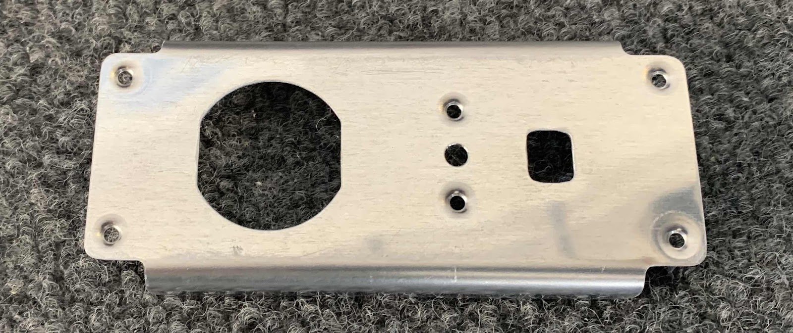
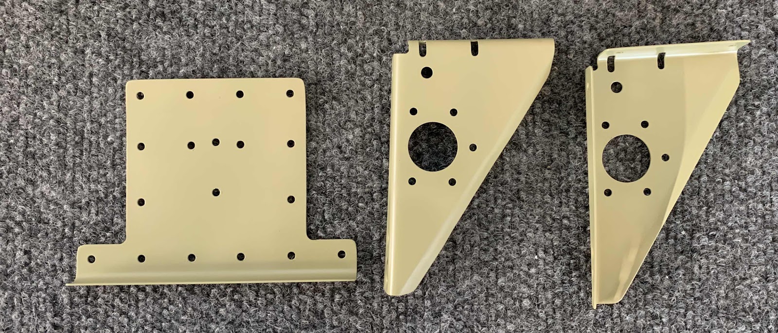
To start this session, we started working on the F-14123 Power Outlet Bracket.  The edges were cleaned, holes deburred and #40 holes dimpled.

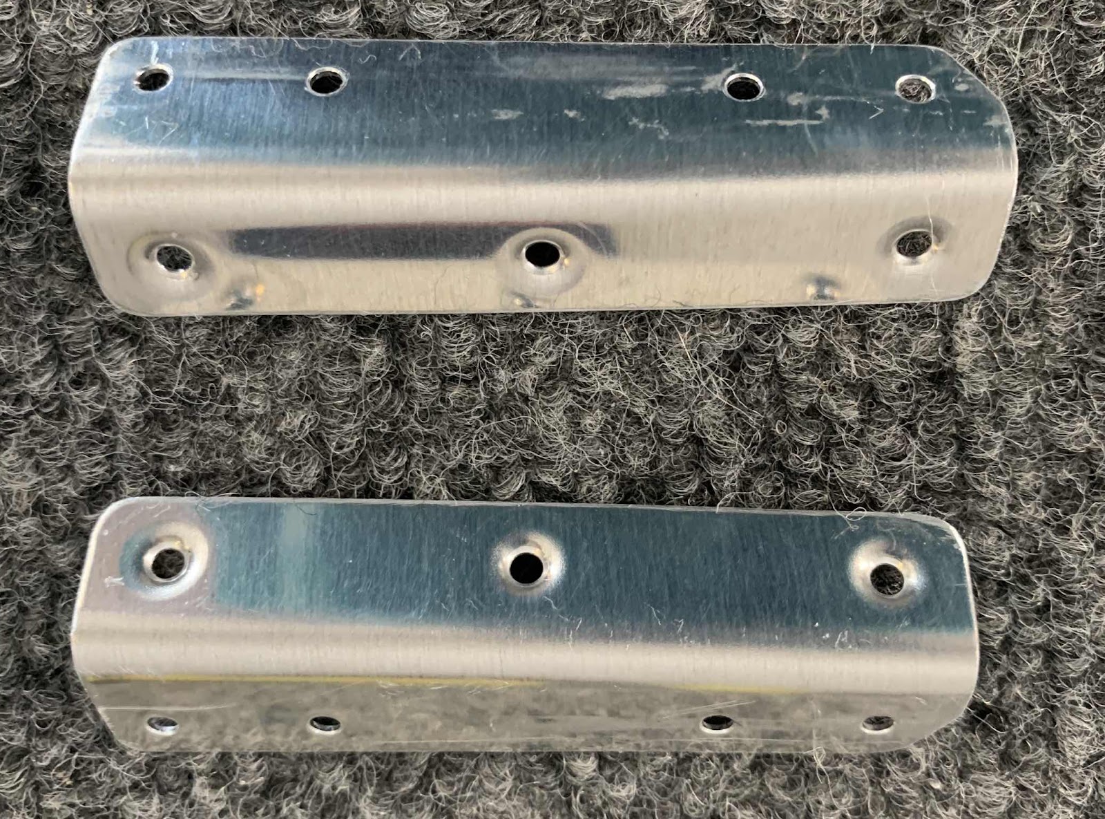
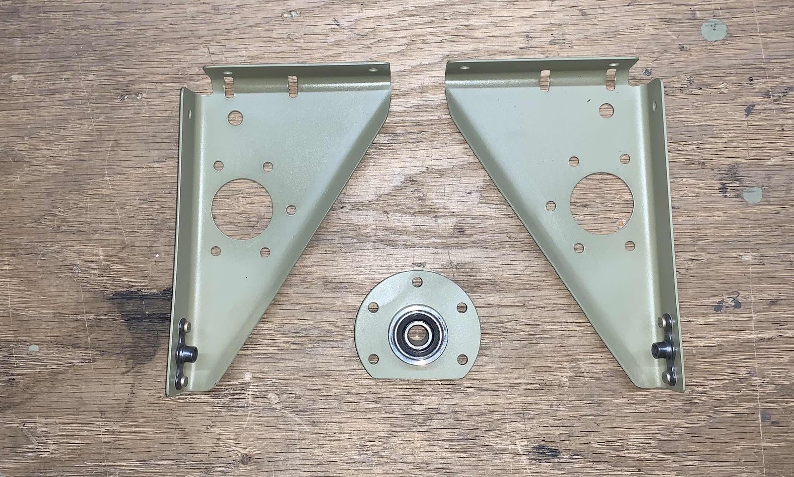
These are the F-14145 Step Attach Angles.  The two angles were also prepared by cleaning the edges, deburring the holes, and dimpling the #40 holes.  NOTE:  these Angles are only necessary to install on the Tri-Gear.....UNLESS the Tailwheel builders wish to install the optional F-00018-L & -R Tail Dragger Steps.  I will be installing the steps, so I prepared the Angles
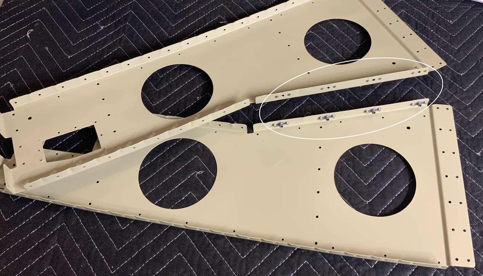
Here is a view of the other side of the Angles.

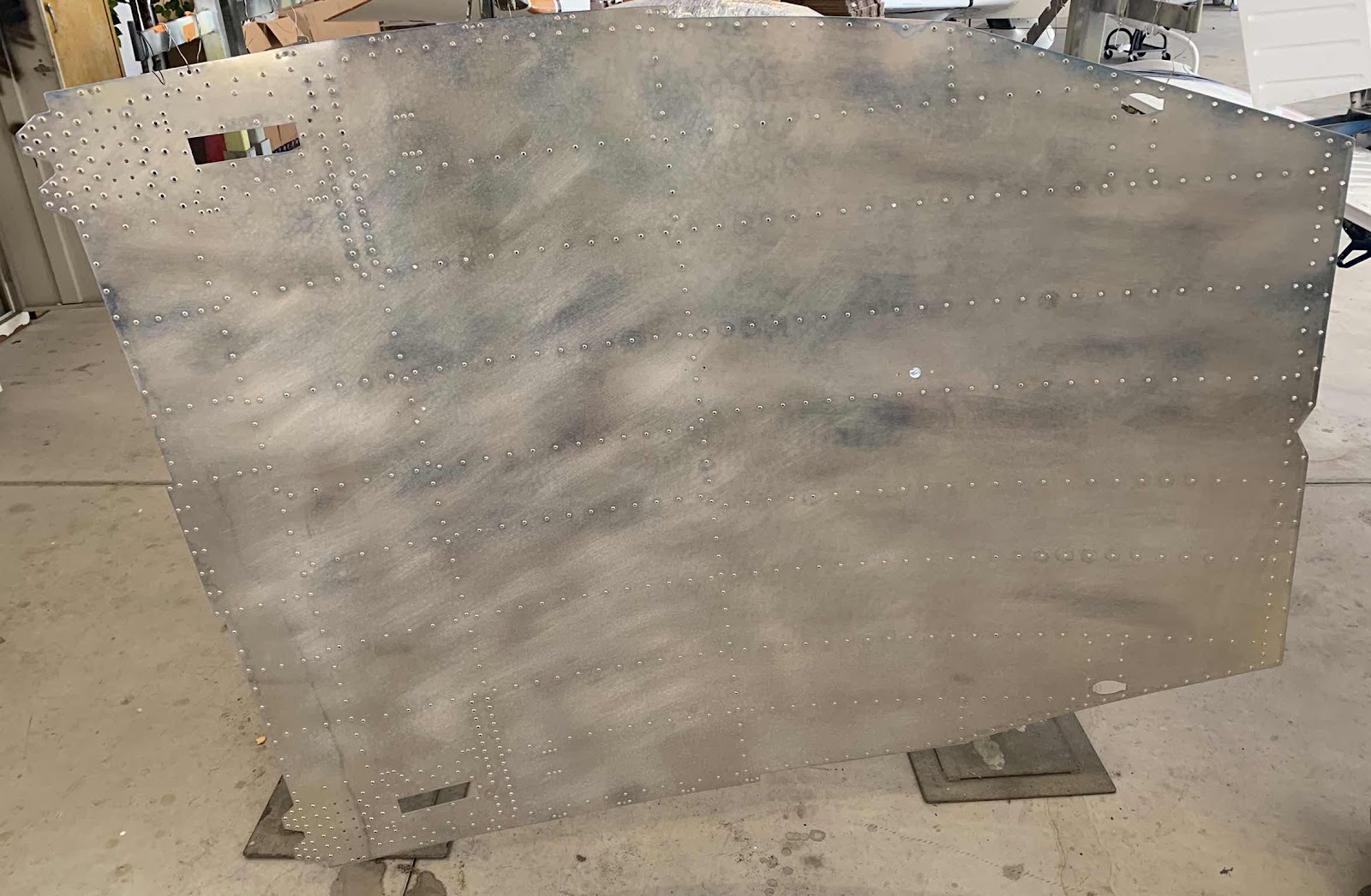
Below is the huge F-01484 Center Bottom Skin after being treated with Alumiprep and Alodine.  It is now hanging up to dry.

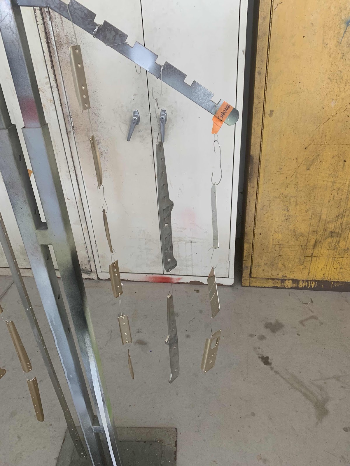
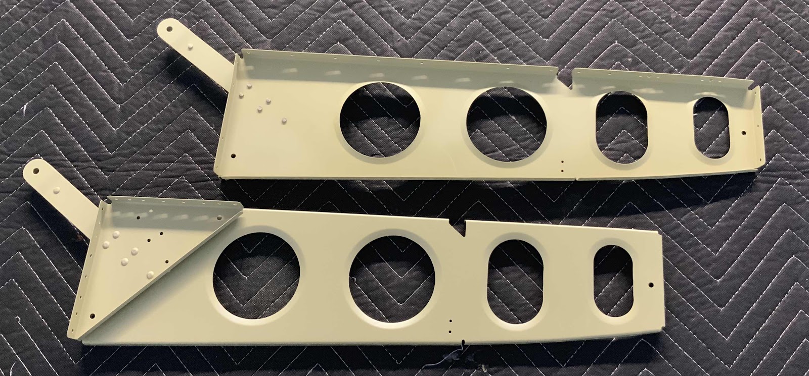
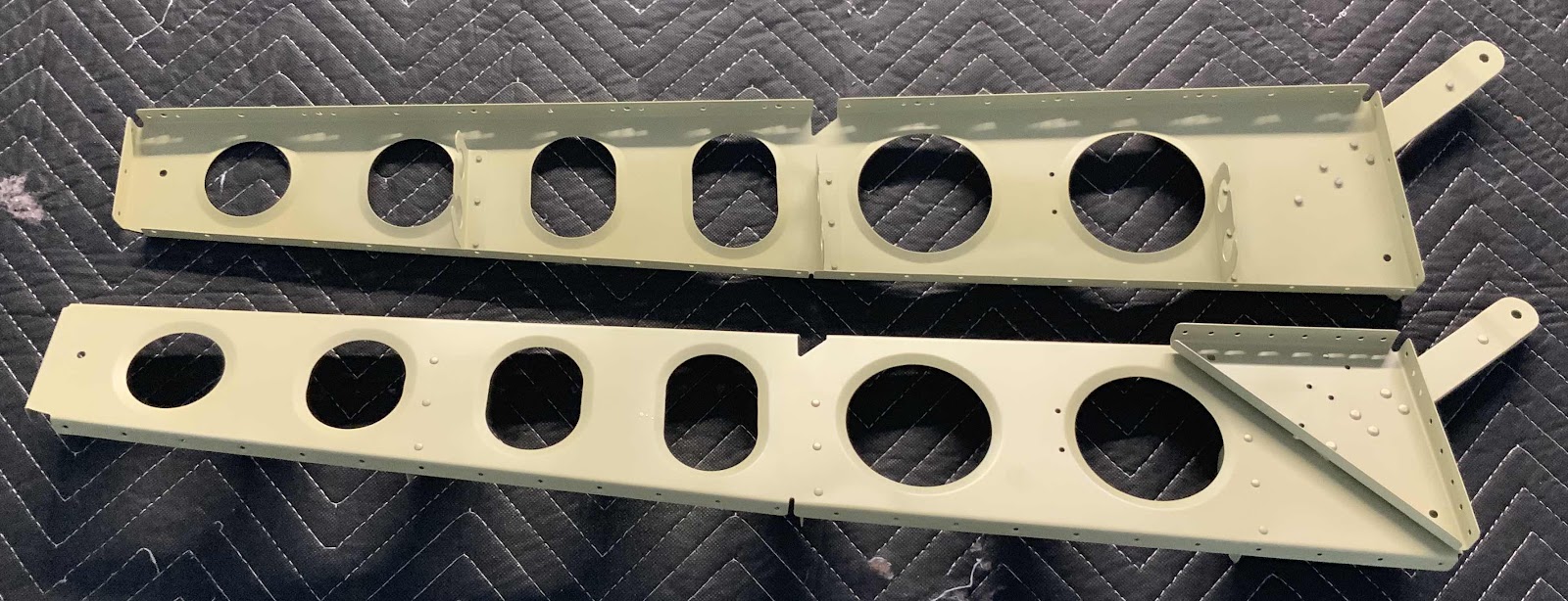
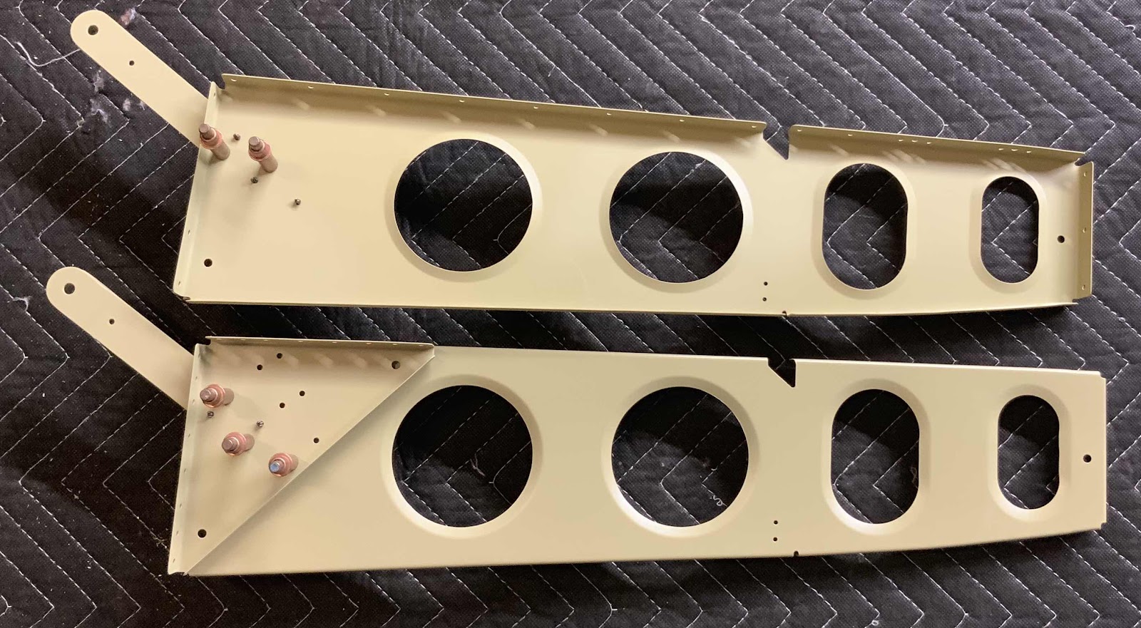
The two pictures below show all the parts I prepared in Parts 16 and 17.  They are also hanging up to dry following treatment with Alumiprep and Alodine.


Saturday, May 25, 2019

Fuselage, MID Lower Structure (Part 17)

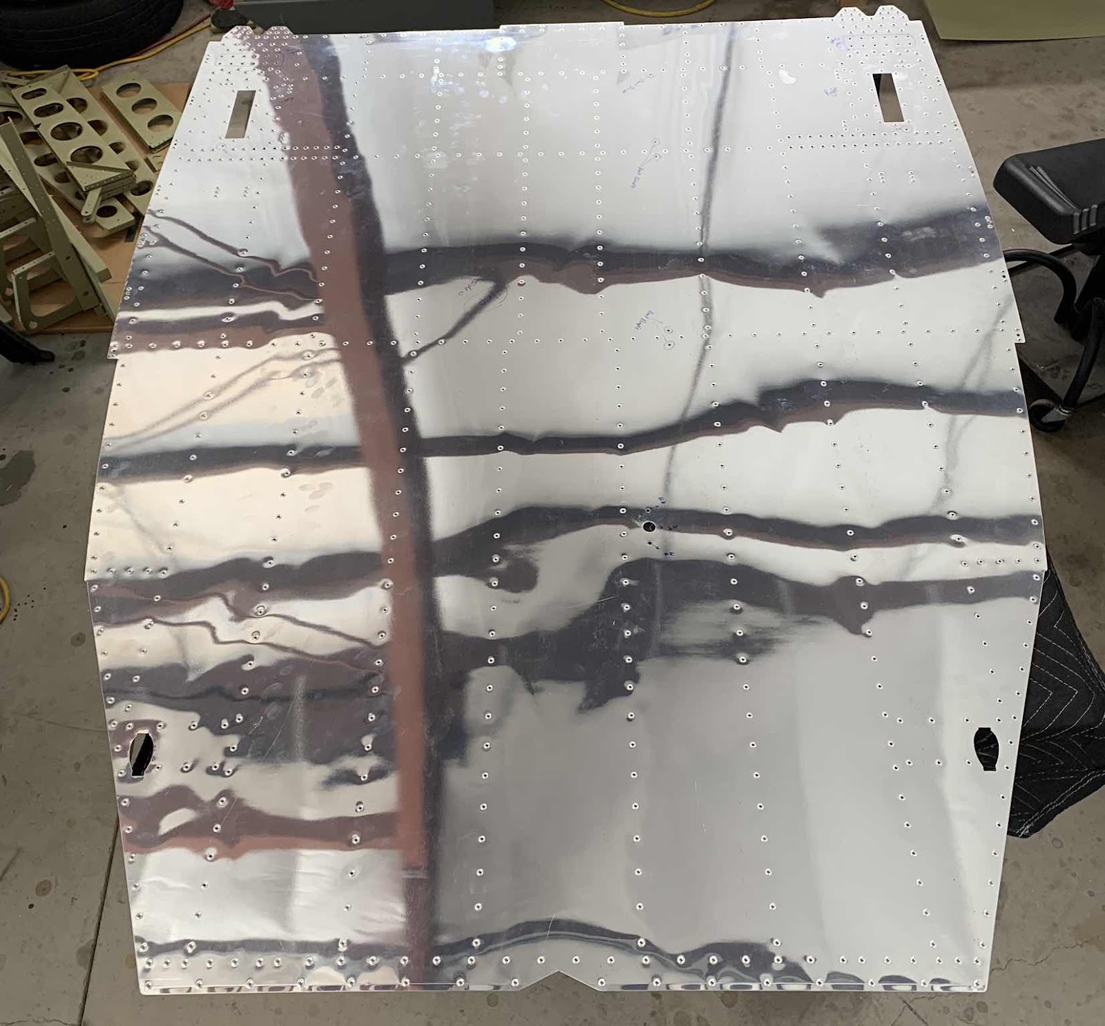
In the previous session, I started dimpling the Center Bottom Skin.  I used my pneumatic squeezer with a 3” yoke to dimple as many of the holes near the edges as possible.  To start today’s session, I used the pneumatic squeezer to finish the holes around the edges and then the DRDT-2 to finish the remaining holes in the Bottom Skin.  Here is the dimpled Center Bottom Skin.

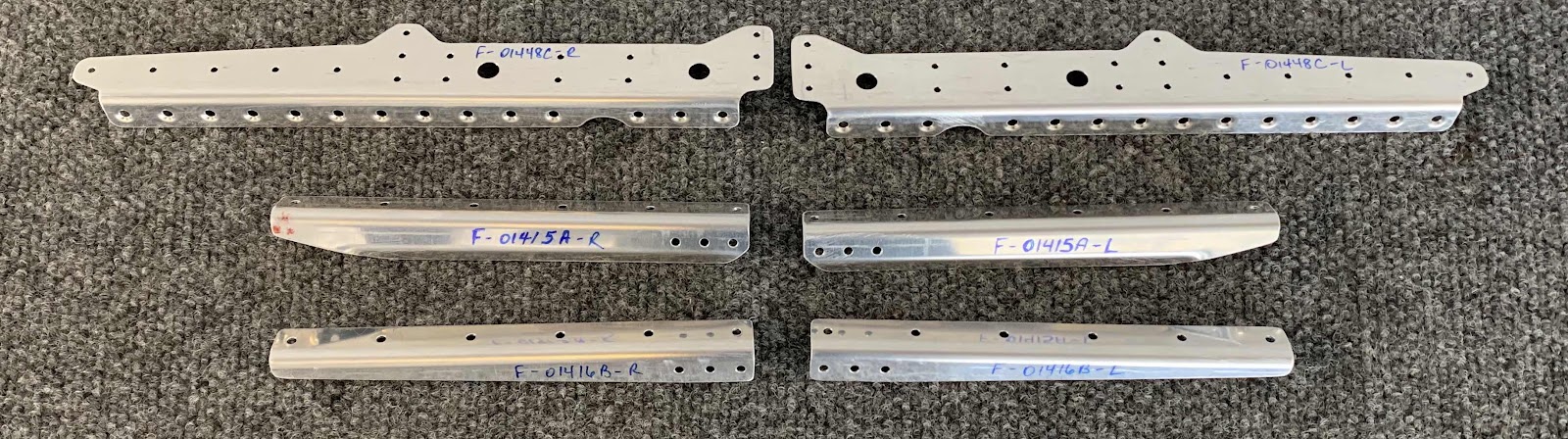
Pictured below is the F-01448C Gear Brace Brackets, F-01415A Seat Rib Angles, F-01416B Seat Rib Angles, and the F-01448B Gear Brace Bars.  The first three parts were connected together in the center and had to be separated into -L & -R parts.  Here’s the three parts after they are separated.....

.....and after the edges are cleaned, all the holes deburred, and the appropriate holes dimpled.  These parts are now ready for Alumiprep, Alodine, and Akzo primer.

Kinda hard to see, but this is the F-01448A Aft Gear Brace.  This part has had the edges cleaned, holes deburred, and the appropriate holes dimpled.  This part is also ready for Alumiprep, Alodine, and Akzo primer.

Sunday, May 19, 2019

Fuselage, MID Lower Structure (Part 16)

Today’s session started to focus on the Forward and Center Bottom Skins and parts that get attached to them.  Let me start by saying, you have to pay VERY close attention to the plans while working on these Skins in this section.....some steps are for trigear version and some steps are for tailwheel version and some steps are for both versions!  I read, re-read, and re-read again to make sure I was doing it correctly.....we will see how well I follow directions.

To start, here are the F-01483-L & -R Forward Bottom Skins.  After skipping all the way to Step #10 (first 9 are for the trigear version), two little #40 holes get dimpled on each Skin (circled below).....

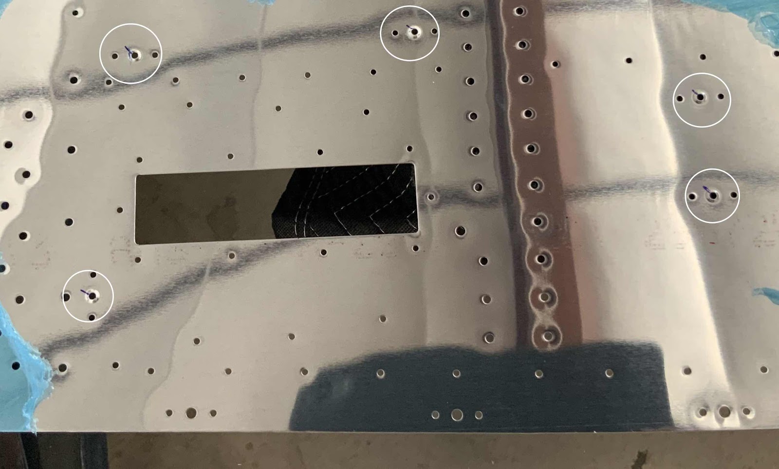
.....and these five #40 holes on the F-01484 Center Bottom Skin get dimpled in Step #11.  Again, you have to pay very close attention to the plans.....look at all those holes in the Skin just daring you to dimple them!!!!!

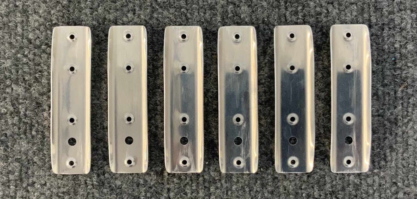
Moving on to the F-14140 Skin Stiffeners.  As with most all of these type of parts, they came all connected in one piece and had to be separated.....in this case into six Stiffeners.  The six Stiffeners below and been cleaned, dimpled and ready to be treated with Alumiprep, Alodine and Akzo primer.

These are the two F-01443 Center Section Lower Doublers.  The upper two rows and lower two rows on each piece had to be machine countersunk to fit a dimpled #30 Skin.  Again, you have to pay attention to the orientations of the parts.  If you notice, the inside upper edges of each piece has a 96º corner vs a 90º for the other three.....subtle, but definitely different!

Here is an excerpt from the plans that shows where these parts will be attached to the Center Bottom Skin.

The next step in the plans is to dimple all the #30 and #40 holes in the Center Bottom Skin (except where previously noted otherwise).  Since the Skin is so big, I started the process dimpling the holes I could reach with a 3” yoke on my pneumatic squeezer.  This will obviously be the holes around the edges of the Skin.  Once that is complete, I will dimple the remaining holes with the DRDT-2.

I’ve dimpled less that 10% of the holes on this Skin, so will pick it up from here on the next session.


Saturday, May 18, 2019

Fuselage, MID Lower Structure (Part 15)

As promised in the previous post, here is the F-01405L Bulkhead Angle (left), shown with the F-01405E-L & -R Idler Brackets after getting treated with Alumiprep, Alodine, and Akzo Primer.

Here is another picture of the Idler Brackets with the trimmed VA-146 Bearing.....also after being treated with Alumiprep, Alodine, and Akzo Primer.  You can also see the two K-1000-08D nutplates installed on each of the Brackets.

Shown below is the F-01405L Bulkhead Angle riveted into place on the F-01405 Bulkhead using eight AN470AD4-4.

Shown below is the Idler Brackets riveted together with the VA-156 Bearing in between.  This view shows the manufacture heads of the rivets (and small smiley).....

.....and the shop head side of the rivets.

The two pictures below aren’t part of the MID Lower Structure section.  However, it only took about 3 minutes to prime these ends, so I included them here.  Since I already had some Akzo Primer mixed up, if figured this would be an appropriate time to prime them.  To do so, I removed the stop nut and bearing from each end, taped off the end, and sprayed the primer.  Pretty easy and pretty quick!  This is one end of the Torque Tubes.....

.....and this is the other end.

Friday, May 17, 2019

Fuselage, MID Lower Structure (Part 14)

In the previous post, I clecoed several assemblies together.  Today, those assemblies were permanently riveted together.  These are the two F-01424-L & -R Baggage Ribs, two F-14128 Seat Belt Lug Brackets, and four F-01480 Seat Belt Attach Lugs.  Each assembly was riveted together with five AN470AD4-6 universal rivets.  The top Ribs shows the shop head side of the rivets and the bottom Rib shows the manufactured head side of the rivets.

These are the two F-01427-L & -R Baggage Ribs, two F-14128 Seat Belt Lug Brackets, four F-01480 Seat Belt Attach Lugs and six F-14100 Routing Angles.  Just like with the Ribs above, these assemblies were riveted together using five AN470AD4-6 universal head rivets.  The six Routing Angles (three on each Rib) received AN470AD3-3 rivets.

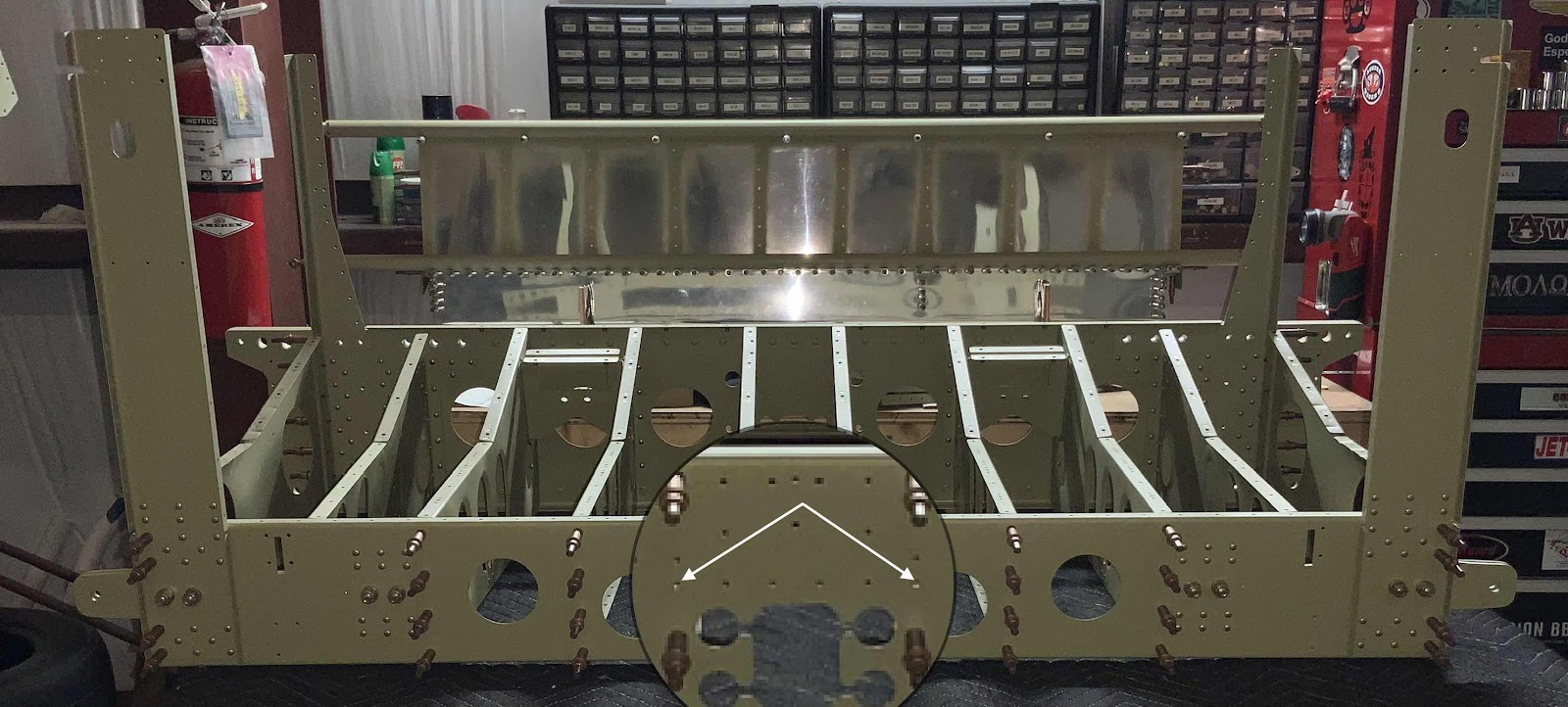
The next step was to Cleco the F-01405 Bulkhead to the F-01417-L & -R Inboard Seat Ribs (middle six Ribs) in order to match-drill two #30 holes.  The two holes were match-drilled in the F-01405L Bulkhead Angle (not shown, but will be in the next post), the F-01405 Bulkhead and F-01417-L & -R Inboard Seat Ribs in the location marked by the white arrows.


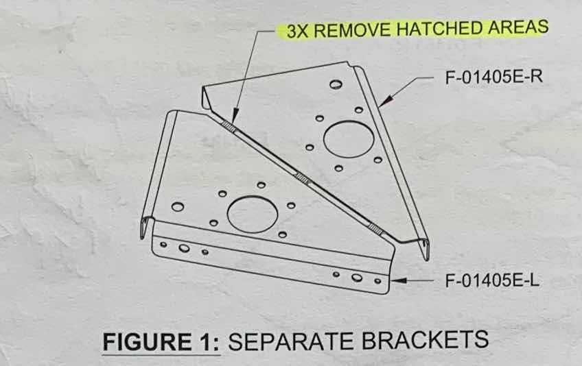
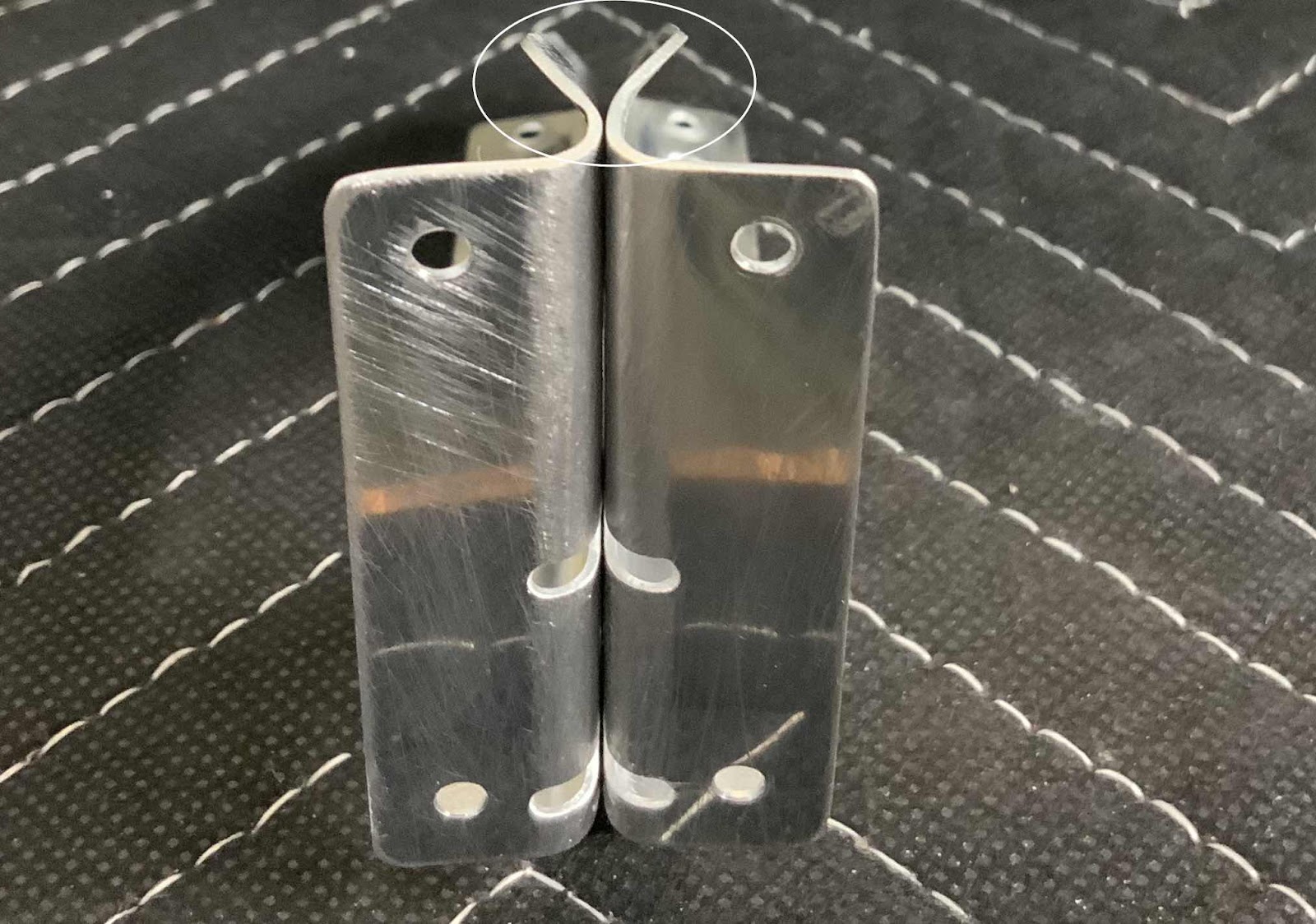
As shown in the plans excerpt below, the F-01405E Idler Bracket(s) had to be separated into a -L & -R, deburred and the #40 holes dimpled.


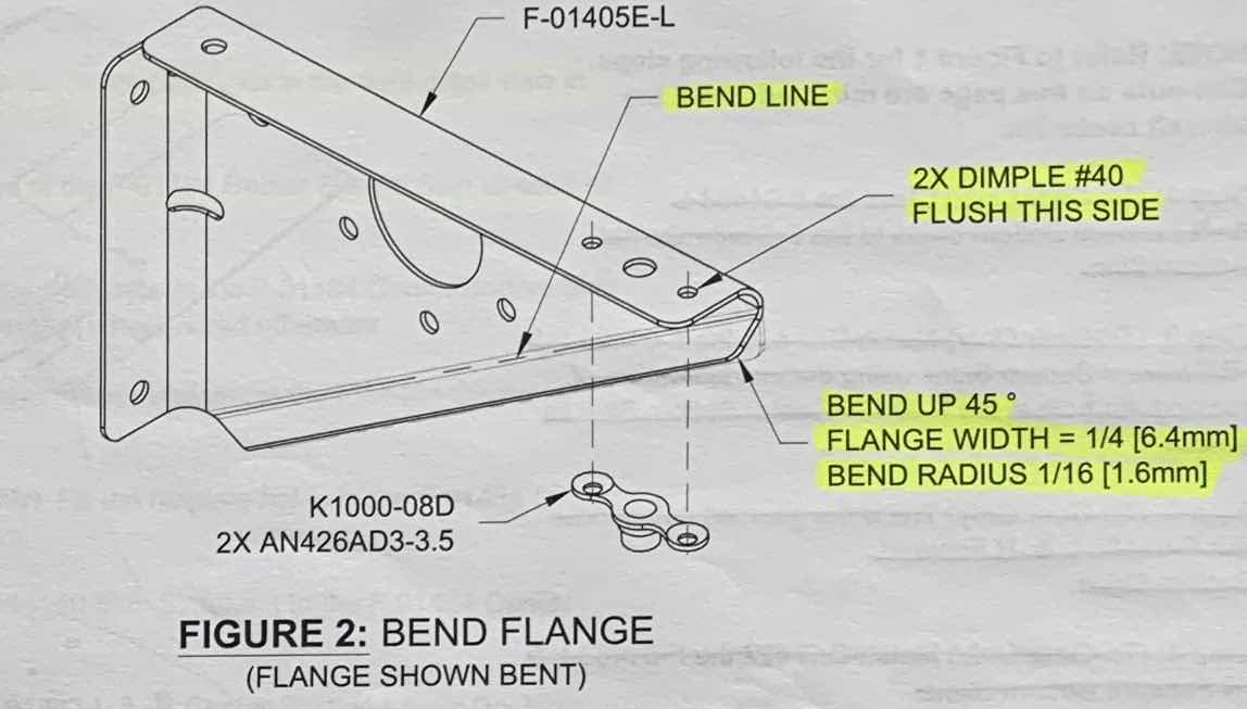
Additionally, the flange that previously connected the two parts had to be bent UP 45º.


I thought about several ways to do this.....two blocks of wood, bench vice, tapping it with hammer, tapping it with a flush rivet set in the rivet gun.  None of these options “felt” right.  So, I ended up using my hand seamer to complete the job.  In the picture below, I’m just showing how I used the seamer on the Bracket.  To make the actual bend, I held the Bracket flat on the workbench, pushed down with the seamer, and bent the flange up.  It took a little small massages to get it right, but the seamer worked perfectly for the job and produced a good product.

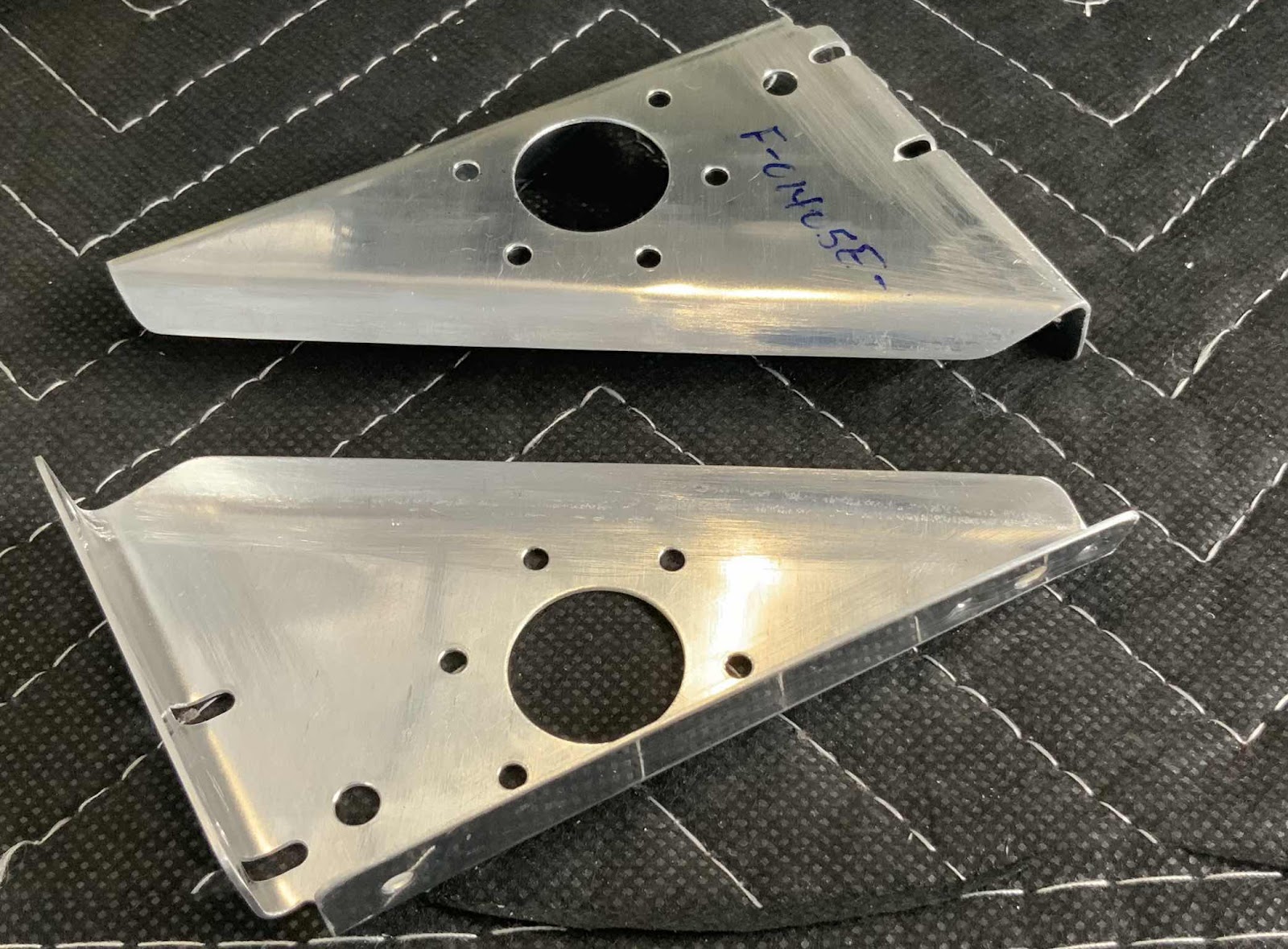
Here are a couple of photos showing different angles of the completed bends on the Brackets.  Lastly, I used a protractor to get the bends to as close to 45º degrees as I could.


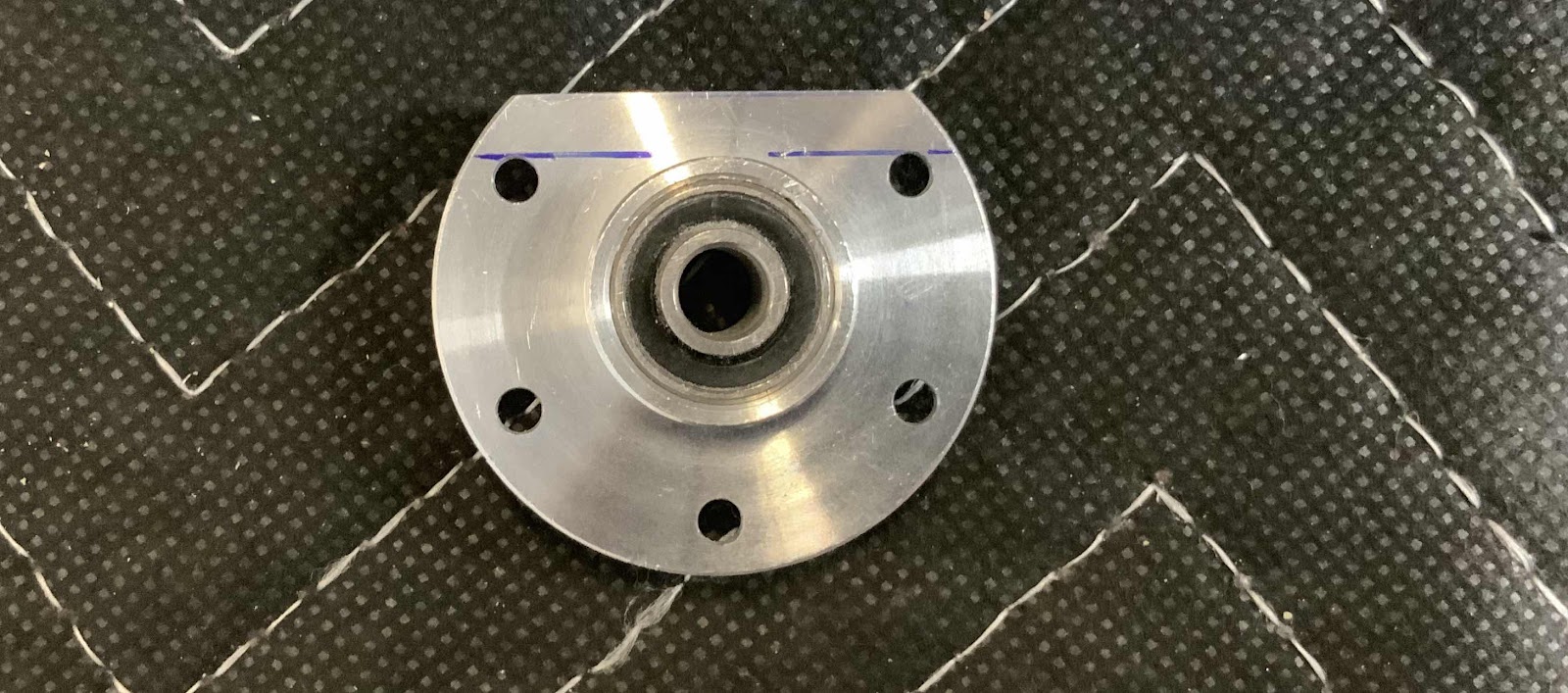
The next exciting step was to remove the top portion of a VA-146 Bearing flange, so it could be riveted between the Idler Brackets.  I used the plans to draw the two blue lines and the blue lines are 4.7mm apart.....as verified by my trustee caliper.  Now, the material above the upper blue line was removed and looks like.....

.....this.  I used the bench grinder to remove a majority of the material and 220 grit sandpaper to make the final adjustments.


Thursday, May 16, 2019

Fuselage, MID Lower Structure (Part 13)

I was able to finish priming the remaining parts today, so here they are after drying.  I put the pictures below in the same order as I do for Part 10 after being treated with Alumiprep and Alodine.

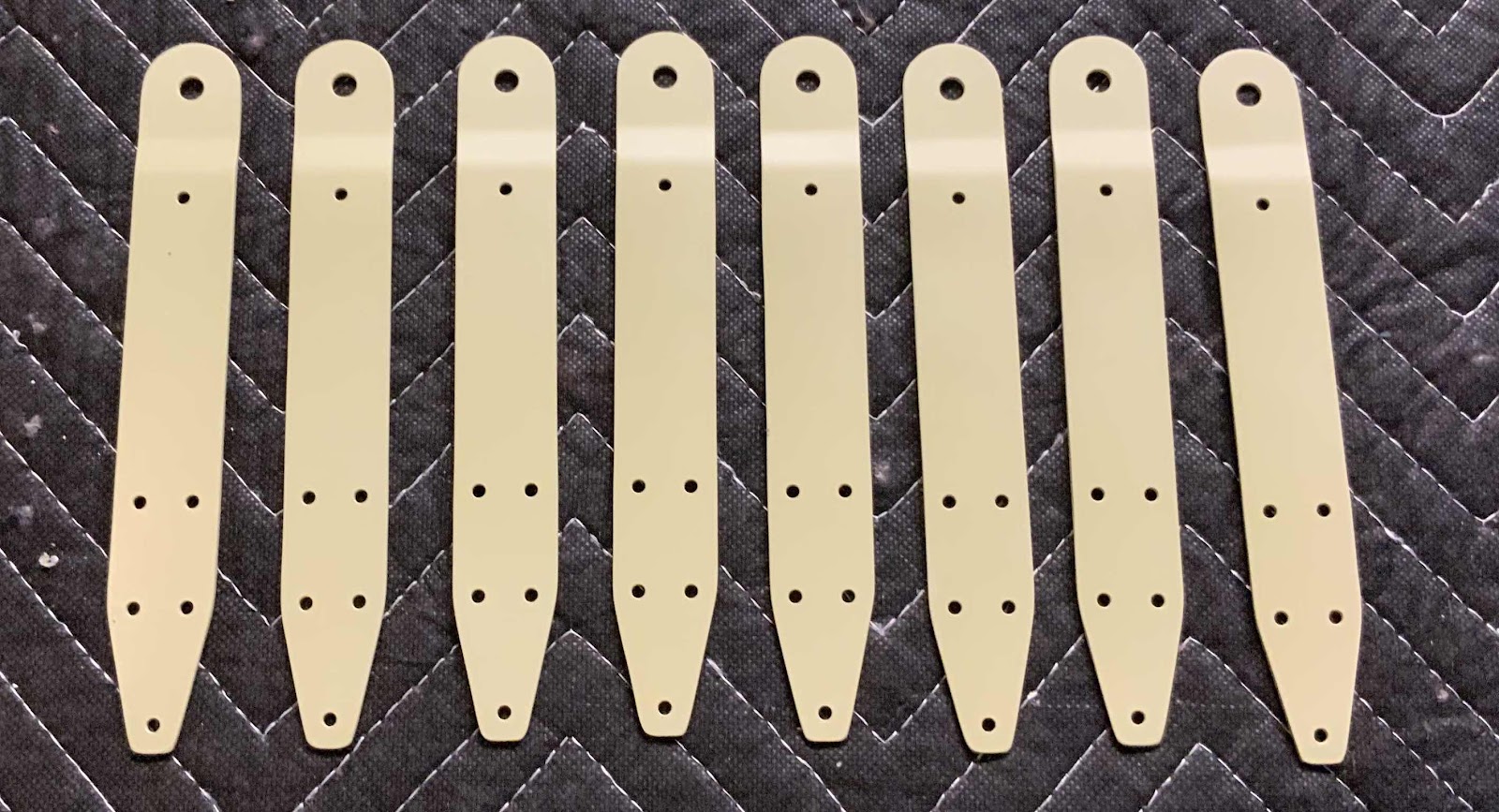
These are the eight F-01480 Seatbelt Attach Lugs.....

.....the four F-14128 Seat Belt Lug Brackets and two F-01424-L & -R Baggage Ribs.....

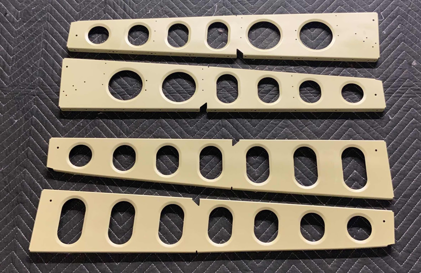
.....the two F-01427-L & -R Baggage Ribs (on the top) and the two F-01426-L & -R Baggage Ribs (on the bottom).....

.....and the two F-01415-L & -R Outboard Seat Ribs (on the top) and two F-01423A-L & -R Outboard Baggage Ribs (on the bottom).

Now, it’s time to start putting stuff together.  Since the parts have been primed, I can go back a few step and install the eight K1000-08D nutplates (circled below) on the two Outboard Seat Ribs.

The next step is to cleco the F-01480 Seat Belt Attach Lugs and the F-14128 Seat Belt Lug Brackets to the F-01424-L &- R and F-01427-L & -R Baggage Ribs.  Pictured below are the F-01424 Baggage Ribs with Seat Belt Attach Lugs and Brackets clecoed into place.....

.....and the F-01427 Baggage Ribs with the Seat Belt Attach Lugs and Brackets clecoed into place.  These Ribs will also have three F-14100 Routing Angles attached to each one.  You can see them clecoed in place in the web of the top Rib.


I will start installing the associated rivets during the next work session.

Wednesday, May 15, 2019

Fuselage, MID Lower Structure (Part 12)

Today’s session was spend AKZO priming the parts that were prepared in Part 10 and treated with Alumiprep and Alodine in the Part 11.  I was only able to get about half of them primed today, so I’ll try to finish the remaining parts tomorrow.  Once I’m finished, I’ll post some pictures.

Monday, May 13, 2019

Fuselage, MID Lower Structure (Part 11)

Nothing to really show tonight.  All the parts I prepared in the last session were treated with Alumiprep and Alodine today.  They are hanging up to dry and will be Akzo primed during the next session.

Sunday, May 12, 2019

Fuselage, MID Lower Structure (Part 10)

Today’s session was spent preparing Baggage Ribs for Alumiprep, Alodine, and Akzo Primer.

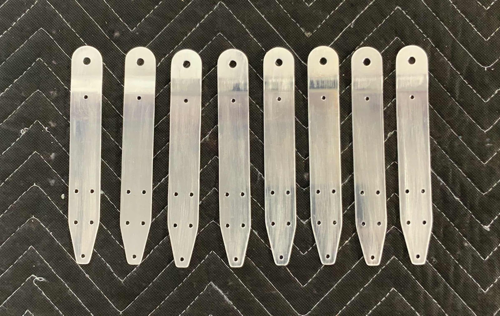
These are the F-01480 Seat Belt Attach Lugs.  They came attached to each other and had to be separated....kinda looked like a rivet fan!  Anyway, I separated them using my bandsaw, cleaned the edges, and deburred the holes.  

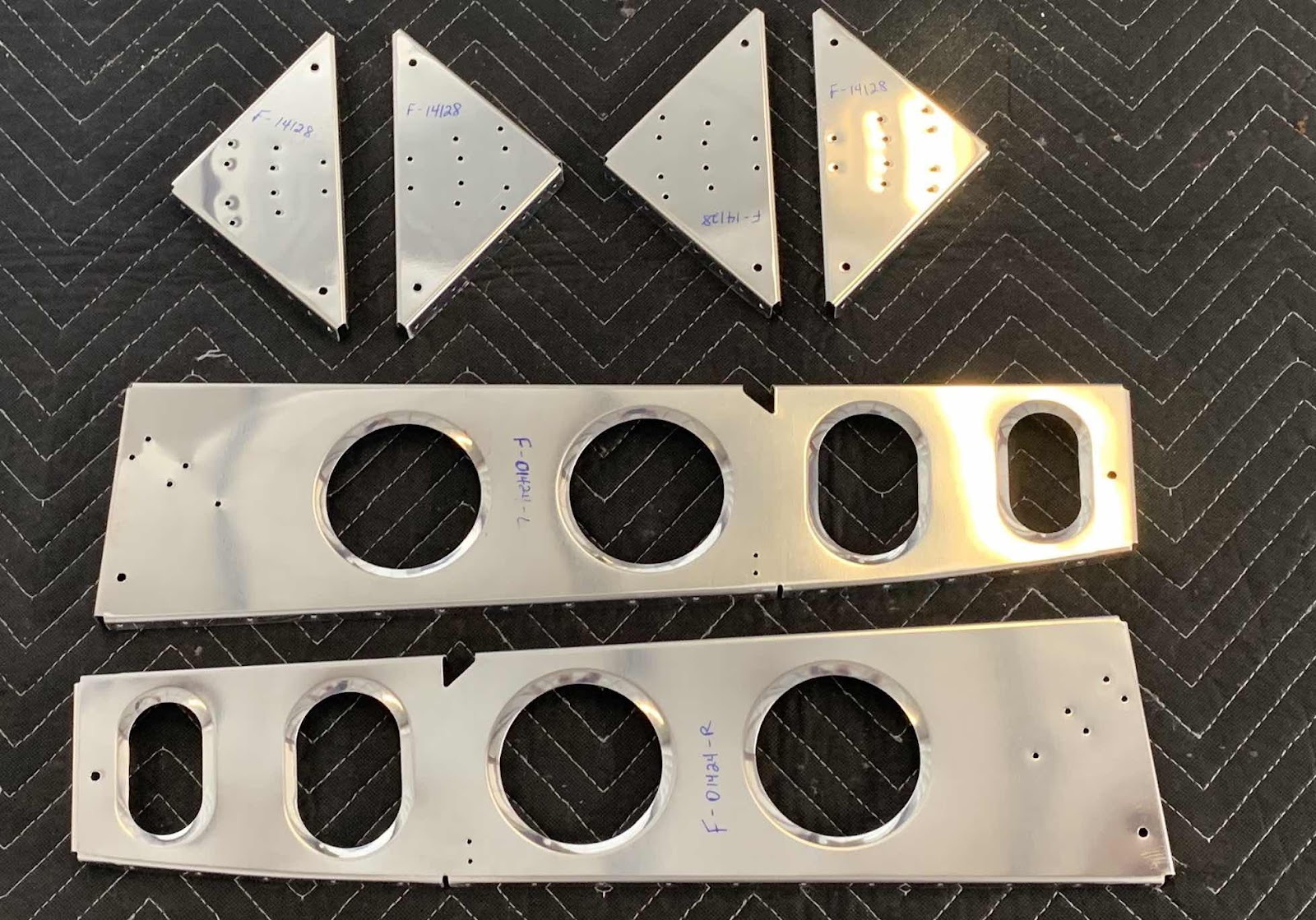
The four triangles (kinda looks like two sandwiches cut diagonally) are the F-14128 Seat Belt Lug Brackets.  The two Ribs are the F-01424-L & -R Baggage Ribs. All the edges were cleaned and the holes were deburred and dimpled.

The Ribs on top are the F-01427-L & -R Baggage Ribs and the Ribs on the bottom are the F-01426-L & -R Baggage Ribs.  All the edges were cleaned and the holes were deburred and dimpled.

The two Ribs on the top are the F-01415-L & -R Outboard Seat Ribs and the two Ribs on the bottom are the F-01423A-L & -R Outboard Baggage Ribs.  All the edges were cleaned and the holes were deburred and dimpled.

I don’t like to dimple holes AFTER I have primed them.  Doing so, usually cracks the primer and it flakes off requiring touch up.  So, I looked several pages ahead to determine which holes get dimpled on these parts.  Now, all the parts above are ready to be treated with Alumiprep, Alodine, and Akzo Primer.

Saturday, May 11, 2019

Fuselage, MID Lower Structure (Part 9)

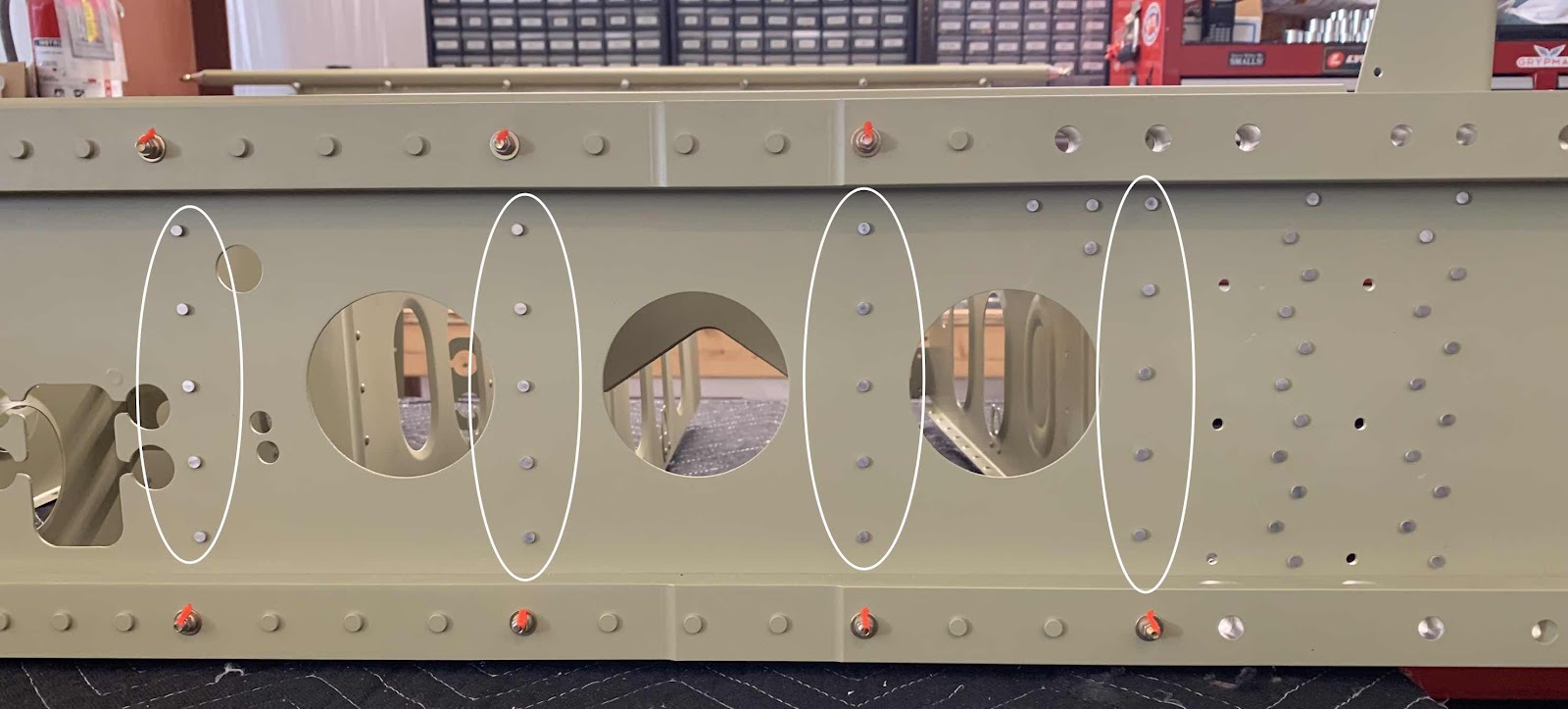
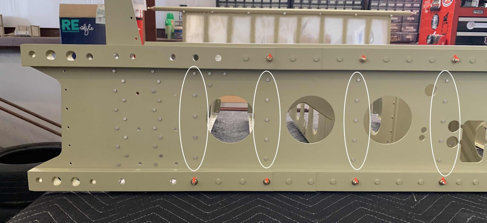
In the last few pictures from Part 8, you can see the copper colored #30 clecos are still holding the Seat Ribs in place to the Bulkhead web.  During today’s session, I used AN470AD4-4 (x30) and AN470AD4-6 (x10) rivets to permanently rivet them together.  Pictured below is the left and right forward side of the Bulkhead showing the shop head side of the rivets (circled in white).


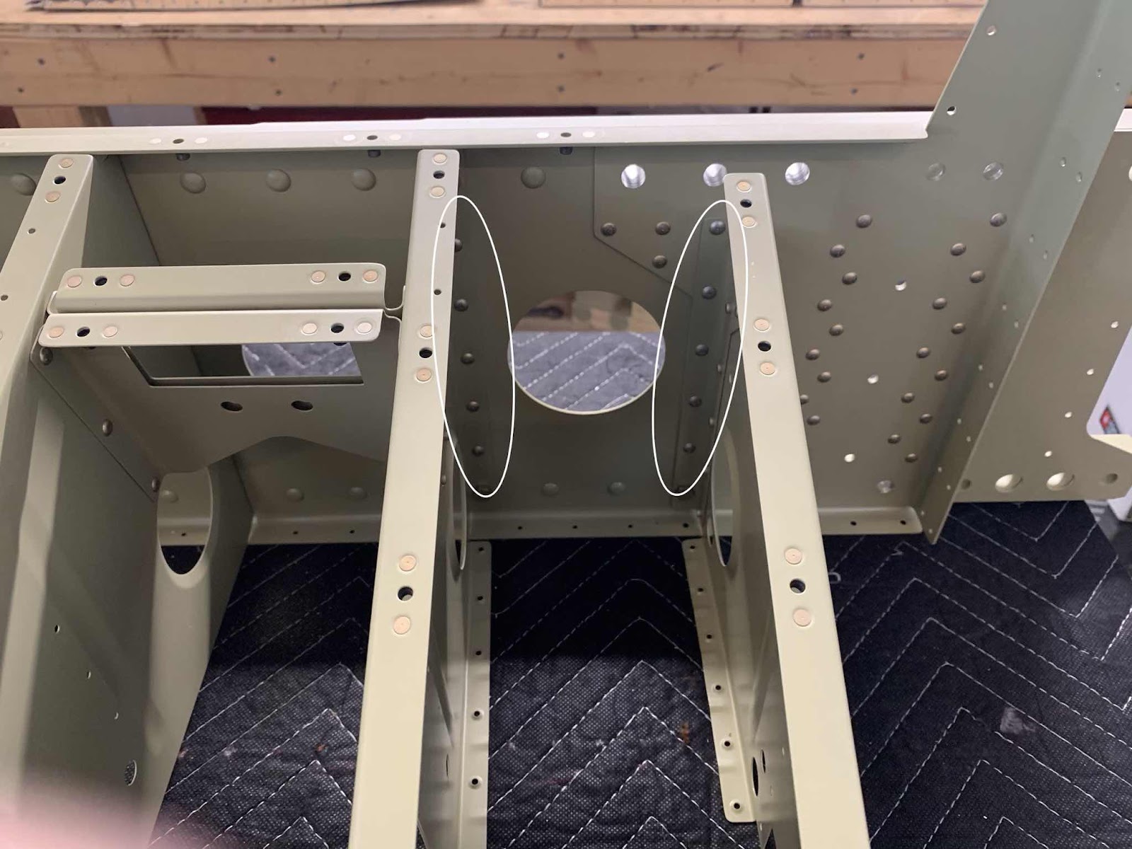
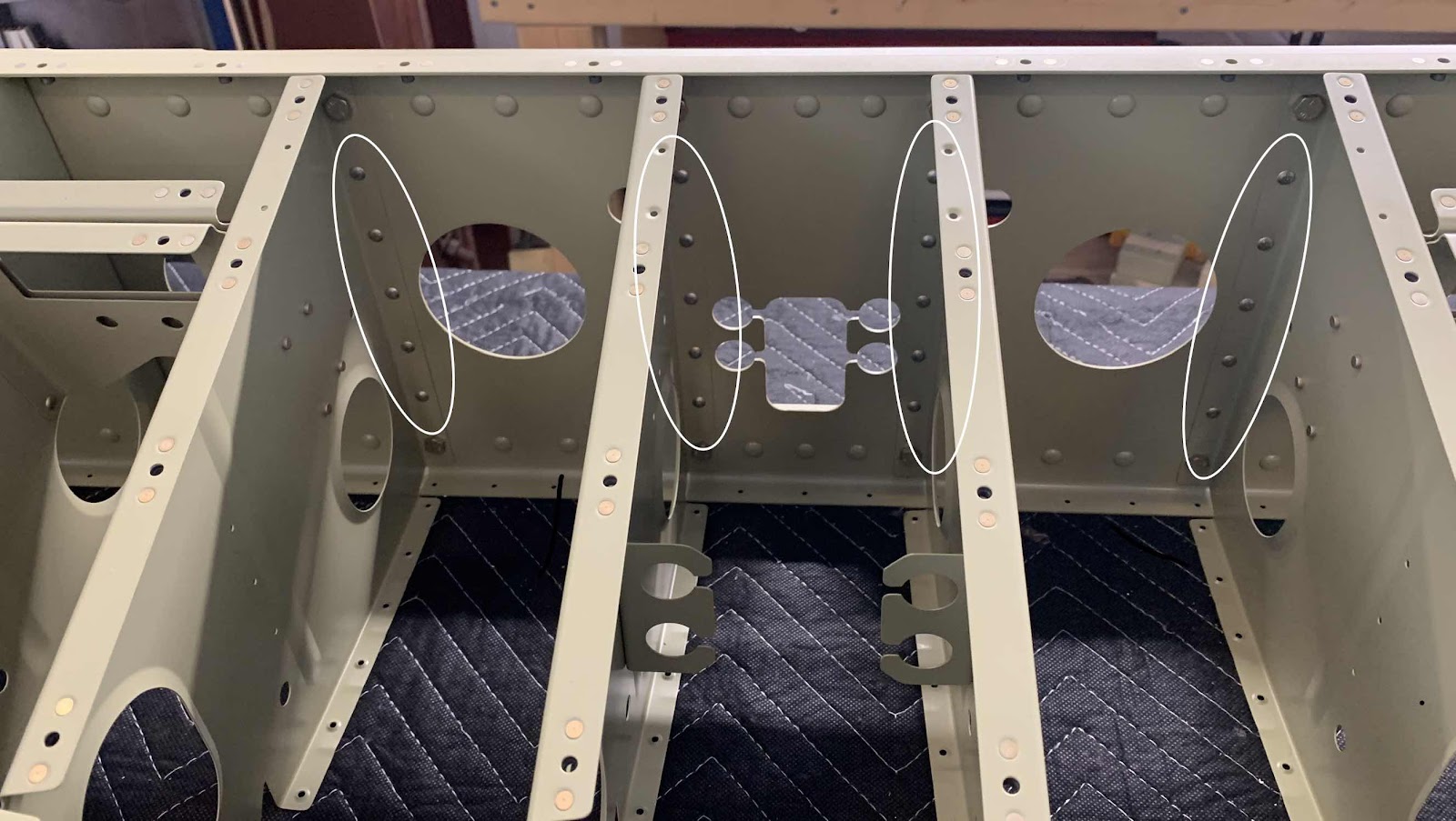
Here is the opposite side (or aft) of the Bulkhead showing the manufactured heads of the rivets.  Here is the right side.....

.....and the left.

I used a 3X rivet gun, tungsten bucking bar, offset rivet set and straight rivet set.  Since the aft side of the Seat Ribs are not attached to anything yet, I was able to move some of them out of the way to use the straight set.  However, I had to use the offset for the Seat Rib rivets near the Crotch Strap Bracket because it is a little “stiffer” in this area.

Wings, Aileron Actuation (Part 2)

In Part 1, the CS-00012 Torque Tubes and VA-11 Threaded Rob Ends were prepared and ready to be Akzo Primed.  I did not treat the Torque Tubes with Alumiprep or Alodine (no particular reason, just didn’t); however, I did scuff the interior and exterior of the Tubes with grey Scotchbrite.  To scuff the inside of the Tubes:

1.  I grabed the Scotchbrite pad with mechanical fingers and taped a long wooden dowel to the end of the mechanical fingers
2.  Inserted the “assembly” into the Tube
3.  Rotated the dowel, which in turn, rotated the Scotchbrite pad
4.  Repeated this process until I was comfortable with the amount of scuffing inside the Tubes

To Akzo Prime the inside of the Tube:

1.  I tapped off one end of the tube
2.  Poured a generous amount of Akzo Primer in the opposite end
3.  Rotated and “twirled” the primer inside the tube until I was comfortable it was completely coated
4.  Poured out the excess primer (if any) and removed the tape

The outside of the Tubes were Akzo Primed simply by holding the middle of the Tubes with my hand and priming the areas I wasn’t holding.  After those sections were hung up and dried, I then primed the areas I was previously holding.  It worked okay, but I’m sure there is a better way.

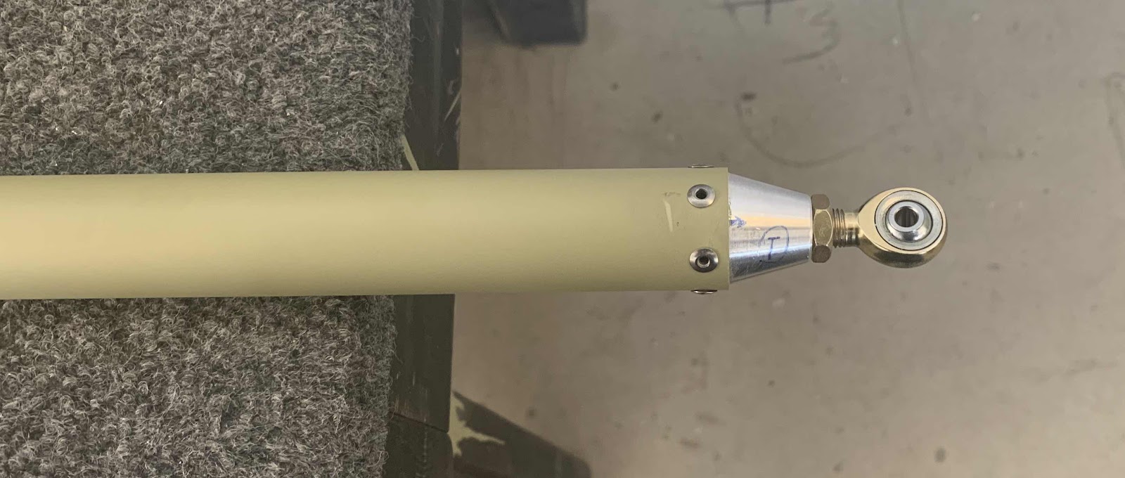
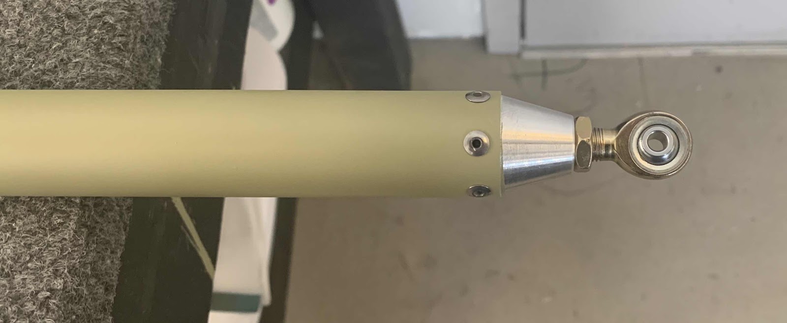
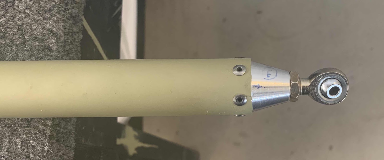
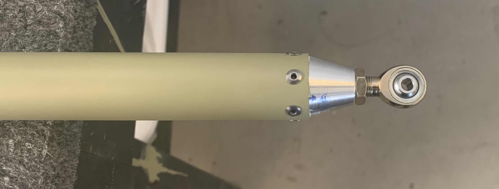
Also in the previous session, each end of the Tubes were marked with a number and the corresponding Threaded Rod End was numbered with the same number.  This was done to ensure the pieces went togher the same way as they were match-drilled.  After the primer was completely dry, I inserted the Threaded Rod Ends into their corresponding Torque Tubes (with a little sanding with 220) and riveted them into place using MSP-42 blind rivets.  Each Tube/Threaded Rod End received  six rivets.

Shown below, in order one through four, are the completed assemblies:


The next time I have primer mixed up, I will use my airbrush to prime the exposed ends of the Threaded Rob Ends.