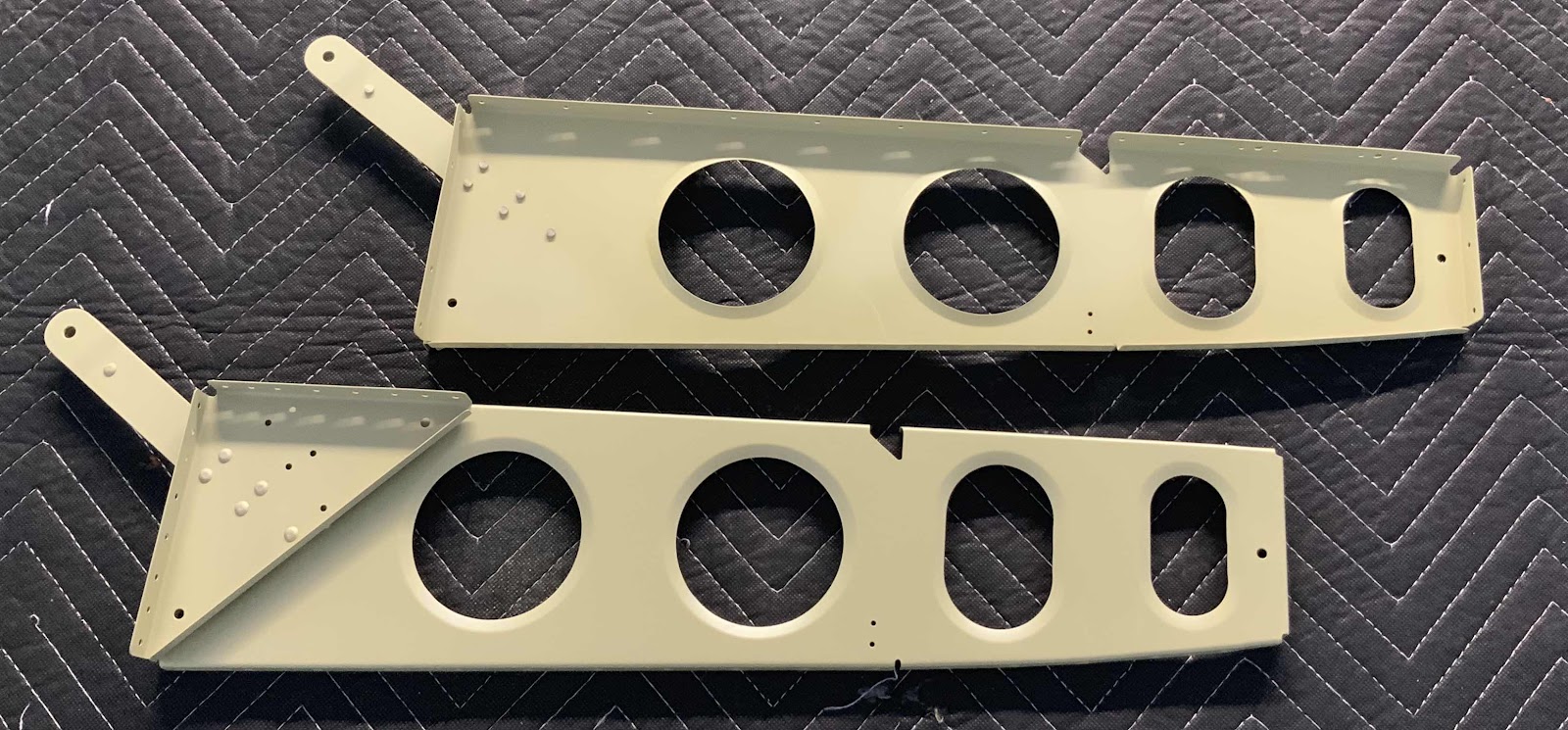
In the previous post, I clecoed several assemblies together. Today, those assemblies were permanently riveted together. These are the two F-01424-L & -R Baggage Ribs, two F-14128 Seat Belt Lug Brackets, and four F-01480 Seat Belt Attach Lugs. Each assembly was riveted together with five AN470AD4-6 universal rivets. The top Ribs shows the shop head side of the rivets and the bottom Rib shows the manufactured head side of the rivets.
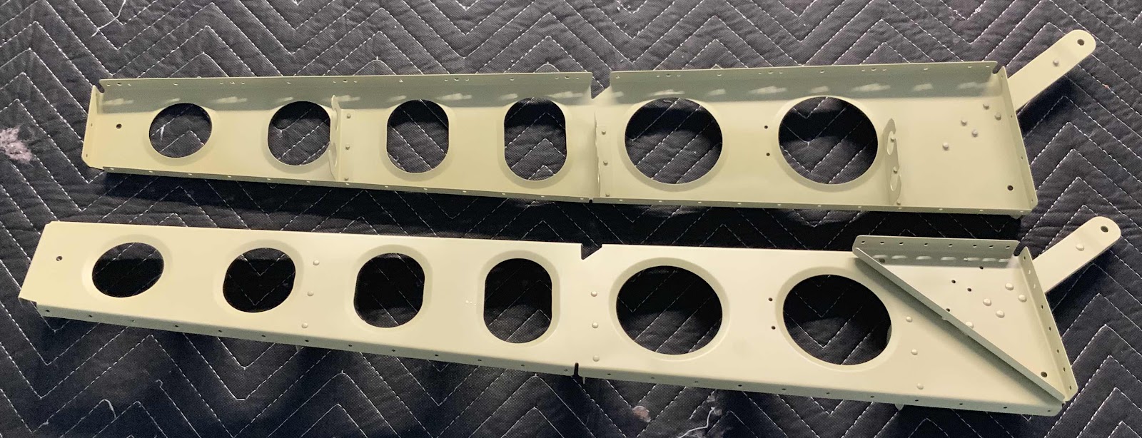
These are the two F-01427-L & -R Baggage Ribs, two F-14128 Seat Belt Lug Brackets, four F-01480 Seat Belt Attach Lugs and six F-14100 Routing Angles. Just like with the Ribs above, these assemblies were riveted together using five AN470AD4-6 universal head rivets. The six Routing Angles (three on each Rib) received AN470AD3-3 rivets.
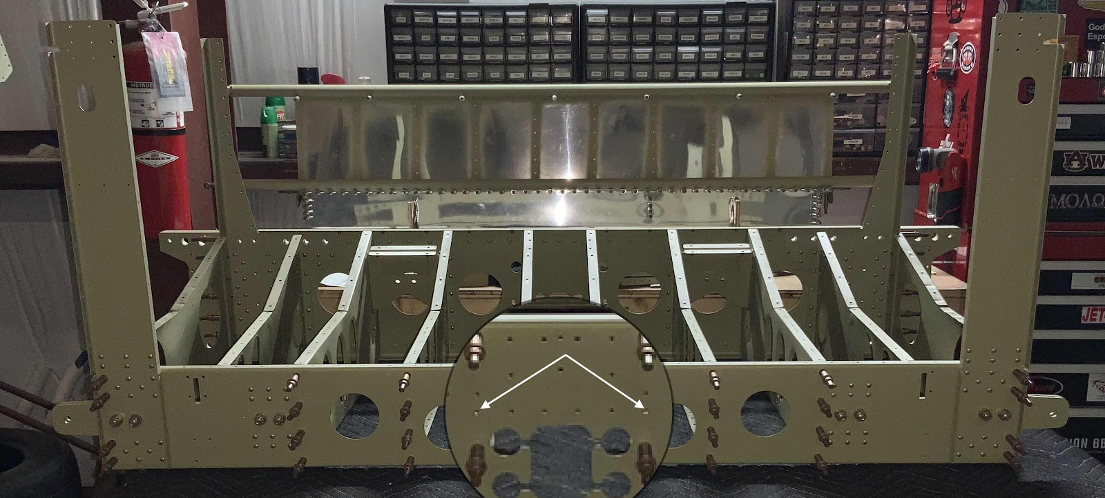
The next step was to Cleco the F-01405 Bulkhead to the F-01417-L & -R Inboard Seat Ribs (middle six Ribs) in order to match-drill two #30 holes. The two holes were match-drilled in the F-01405L Bulkhead Angle (not shown, but will be in the next post), the F-01405 Bulkhead and F-01417-L & -R Inboard Seat Ribs in the location marked by the white arrows.
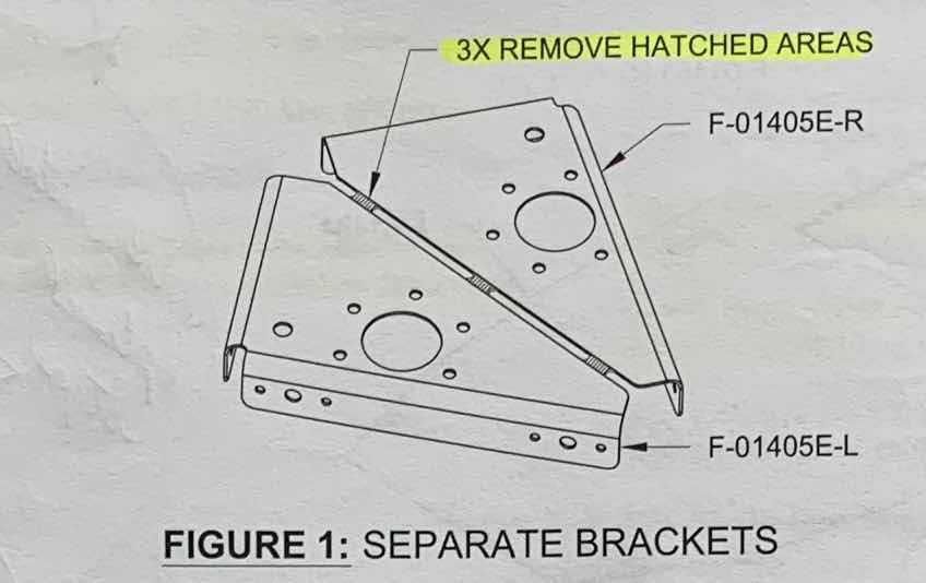
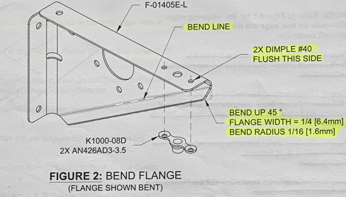
As shown in the plans excerpt below, the F-01405E Idler Bracket(s) had to be separated into a -L & -R, deburred and the #40 holes dimpled.
Additionally, the flange that previously connected the two parts had to be bent UP 45º.
I thought about several ways to do this.....two blocks of wood, bench vice, tapping it with hammer, tapping it with a flush rivet set in the rivet gun. None of these options “felt” right. So, I ended up using my hand seamer to complete the job. In the picture below, I’m just showing how I used the seamer on the Bracket. To make the actual bend, I held the Bracket flat on the workbench, pushed down with the seamer, and bent the flange up. It took a little small massages to get it right, but the seamer worked perfectly for the job and produced a good product.

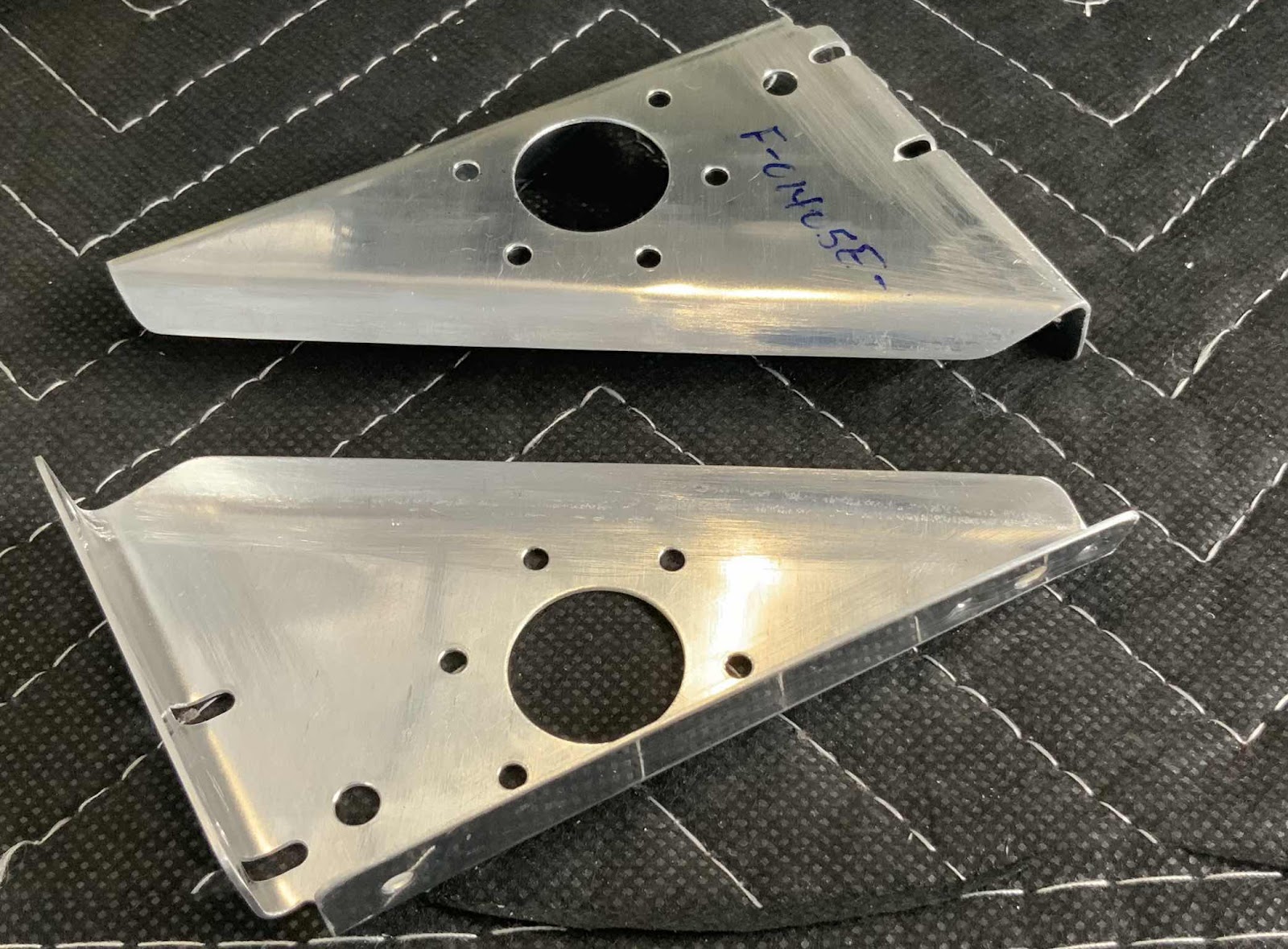
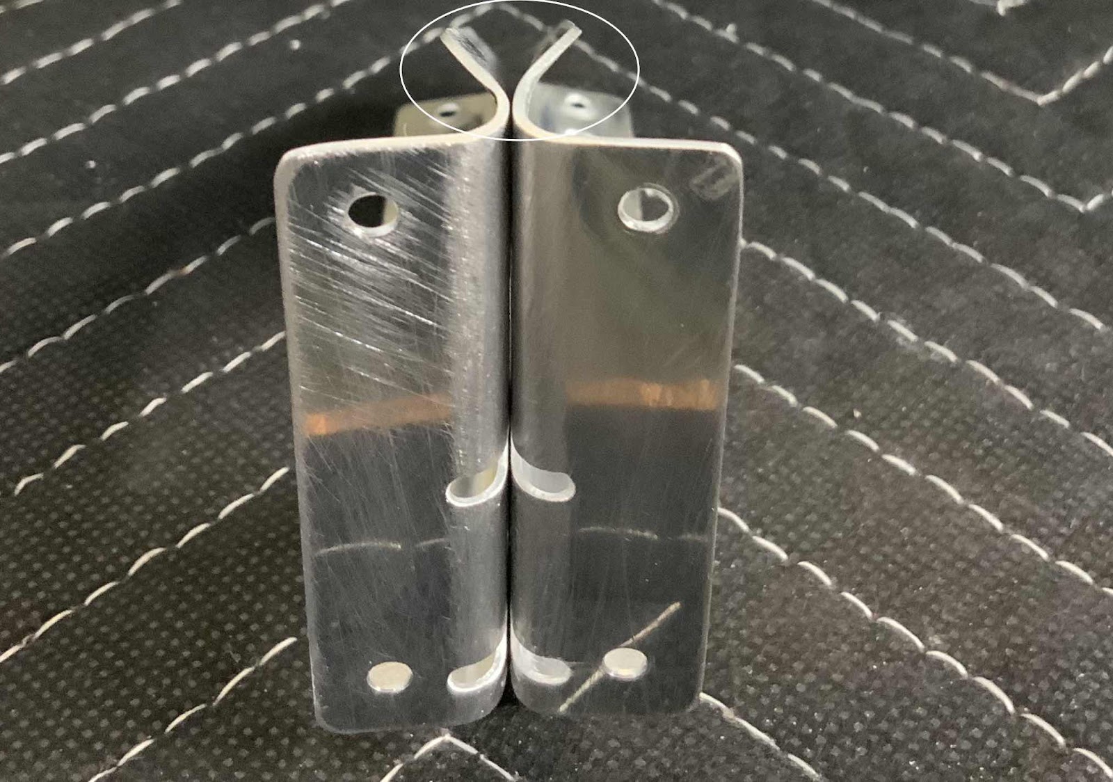
Here are a couple of photos showing different angles of the completed bends on the Brackets. Lastly, I used a protractor to get the bends to as close to 45º degrees as I could.
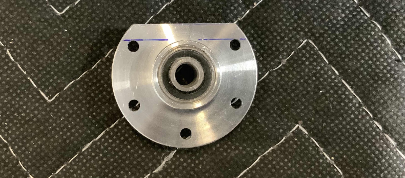
The next exciting step was to remove the top portion of a VA-146 Bearing flange, so it could be riveted between the Idler Brackets. I used the plans to draw the two blue lines and the blue lines are 4.7mm apart.....as verified by my trustee caliper. Now, the material above the upper blue line was removed and looks like.....

.....this. I used the bench grinder to remove a majority of the material and 220 grit sandpaper to make the final adjustments.