Sunday, June 2, 2019

Wings, Ailerons (Part 22)

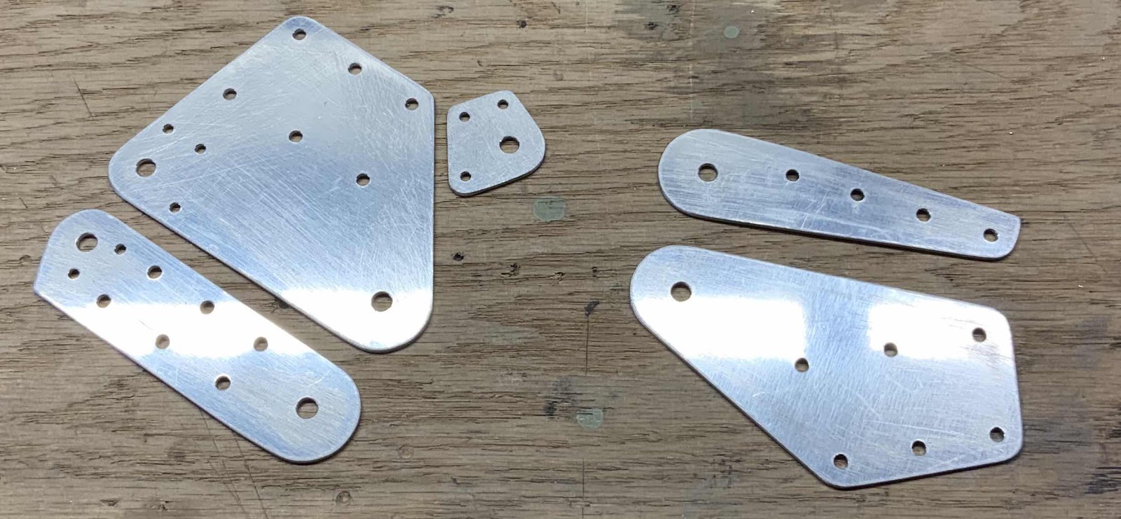
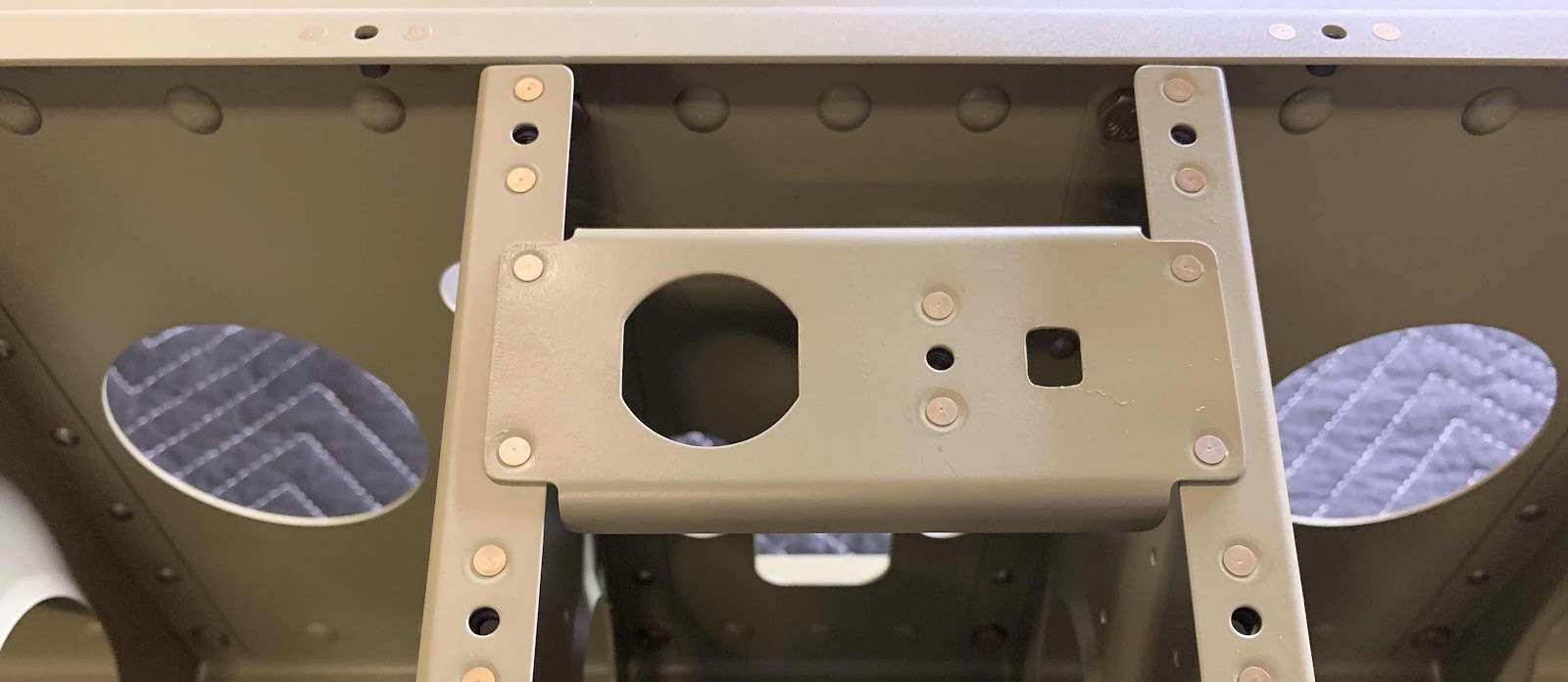
Continuing from yesterday’s session, it’s now time to rivet stuff together.  Pictured below is the A-1005A-1R Main Rib.  In the first picture, you can see the manufactured side of the four AN426AD4-4 rivets attaching the A-10071B Inboard Hinge Bracket to the Main Rib and the manufactured head of the three AN426AD3-4.5 rivets attaching the A-1007-1C Hinge Bracket to the A-1007-1C Hinge Bracket.
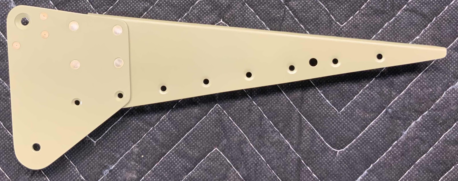
This is the opposite side of the picture above showing the shop head side of the rivets.

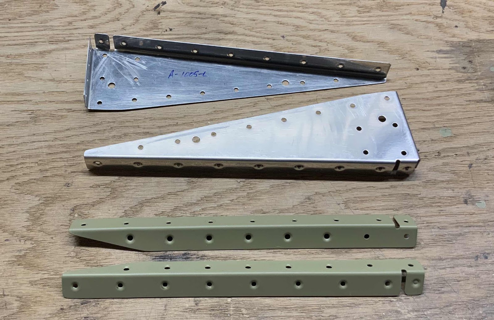
This is the A-1005-1L Main Rib with the A-1006-1B Outboard Hinge Bracket riveted together using four AN426AD4-4 rivets.  This picture shows the manufactured heads.....

.....and the shop heads on the opposite side.

Here is the A-1004-1L Nose Rib with the A-1006-1A Outboard Hinge Bracket rivet into place using four AN-426AD4-4 rivets.
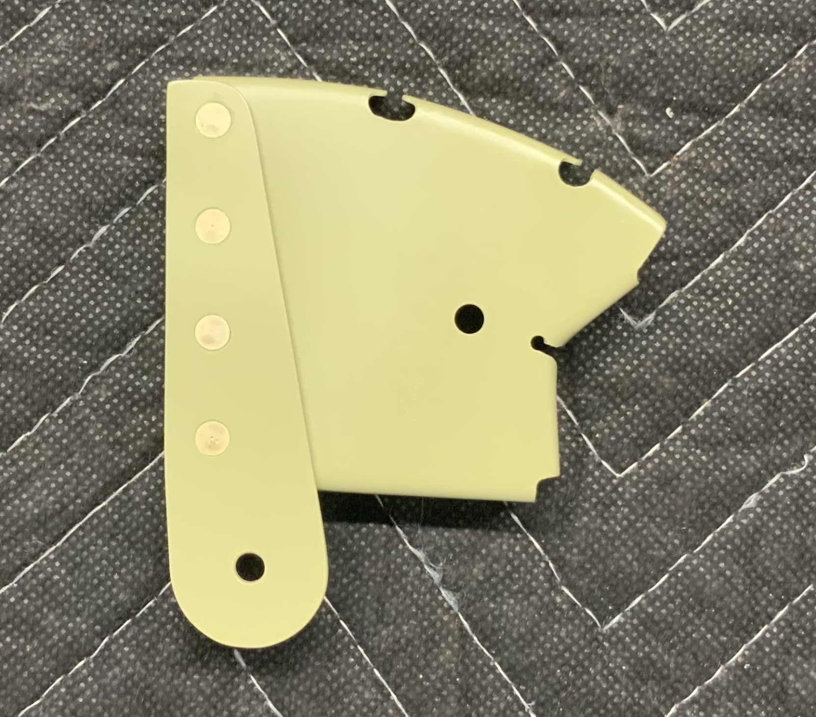
This is the opposite side of the picture above showing the shop head side of the rivets.

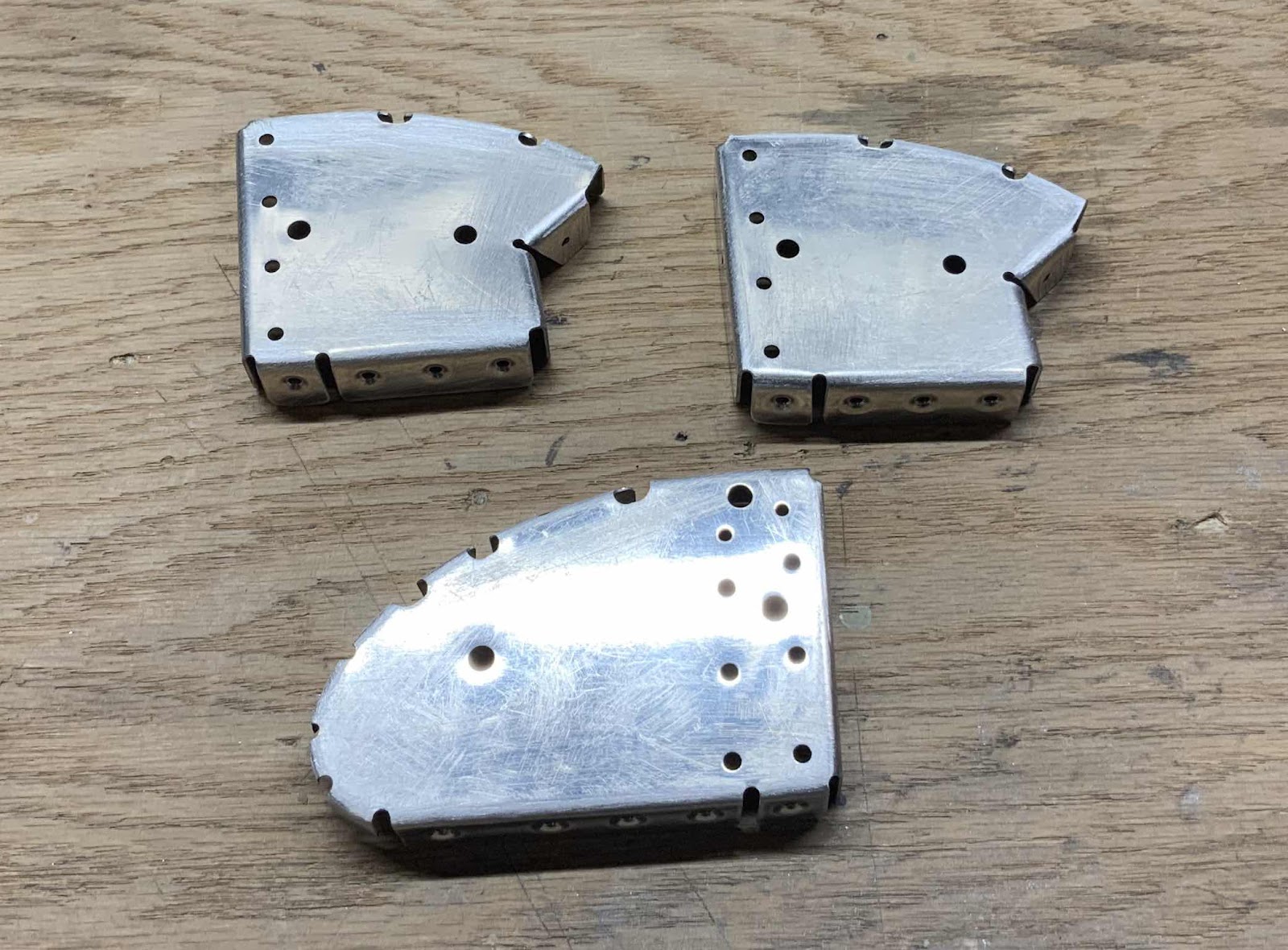
The A-1015-1R Rib with the A-1007-1A Inboard Hinge Bracket riveted into place using six AN426AD4-4 and two AN426AD3-4.5 rivets.
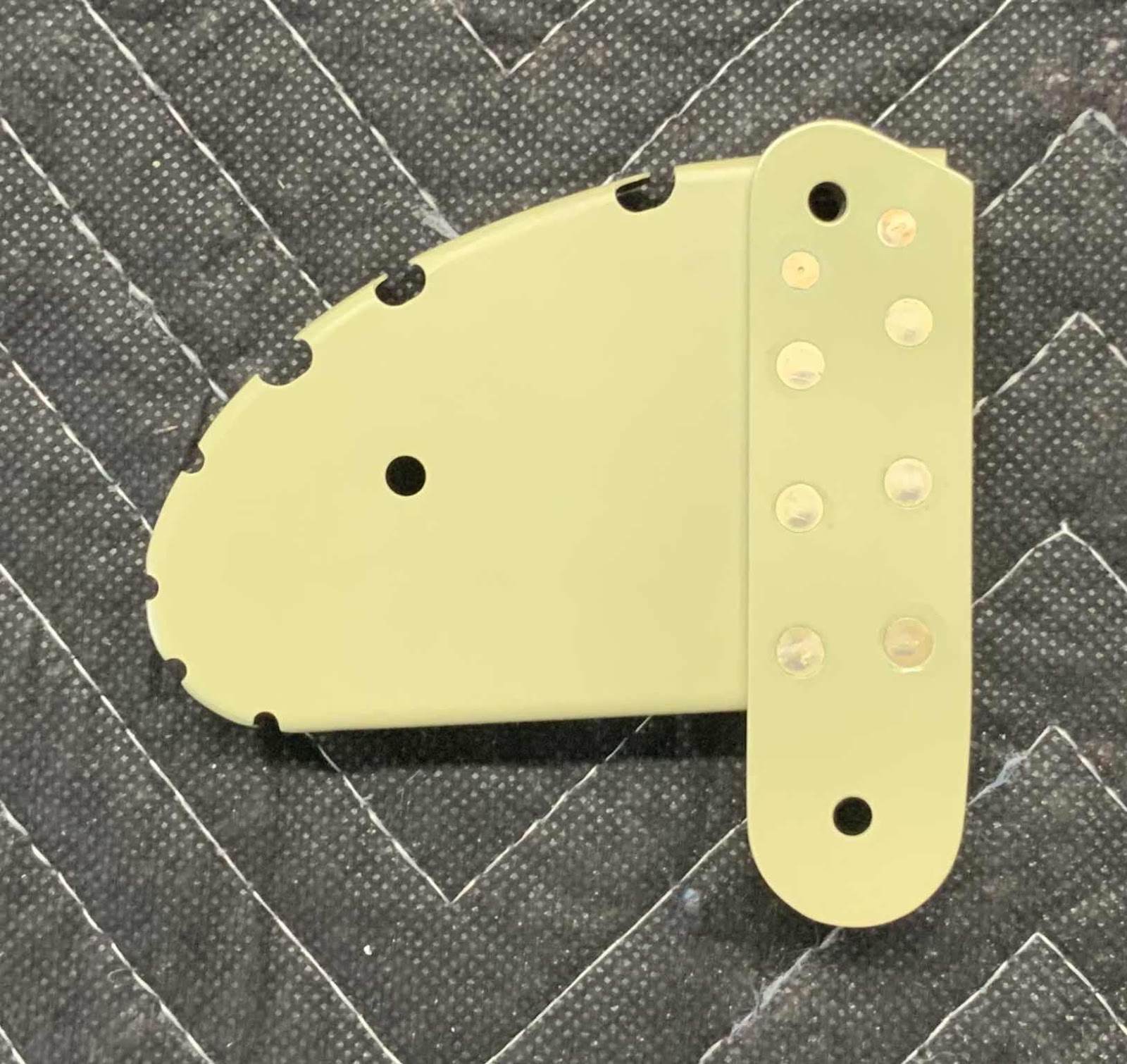
This is the opposite side of the picture above showing the shop head side of the rivets and the single MS21055-L3 nutplate.

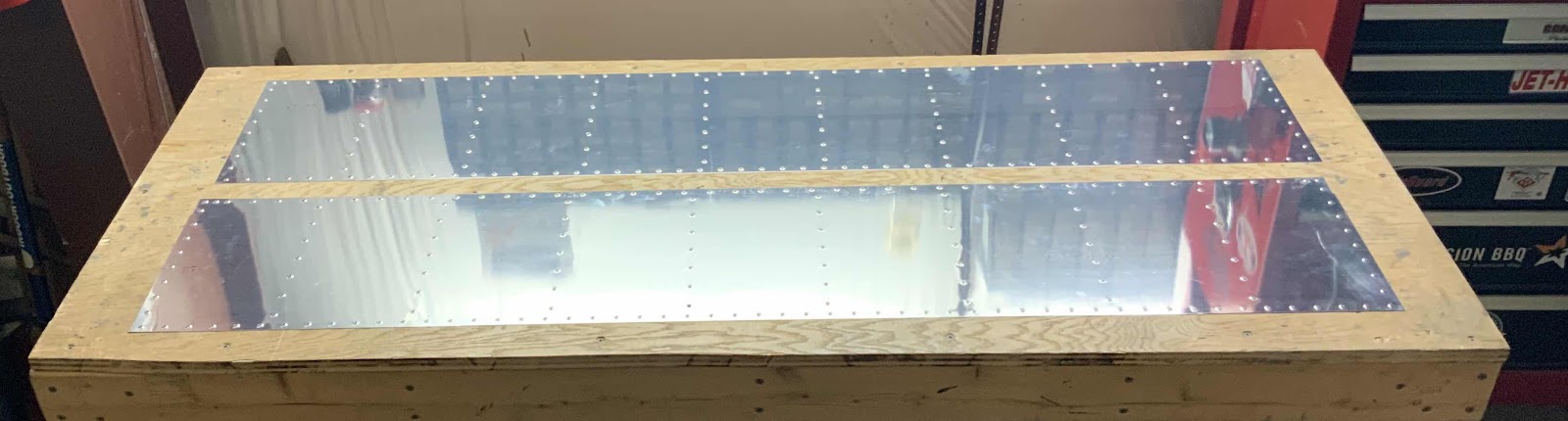
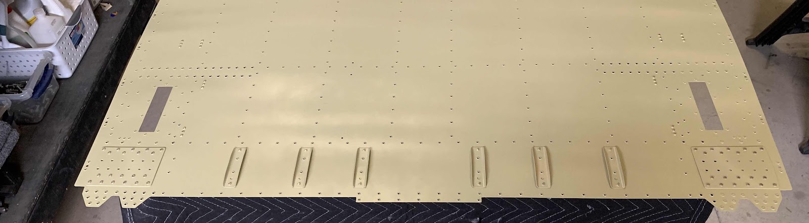
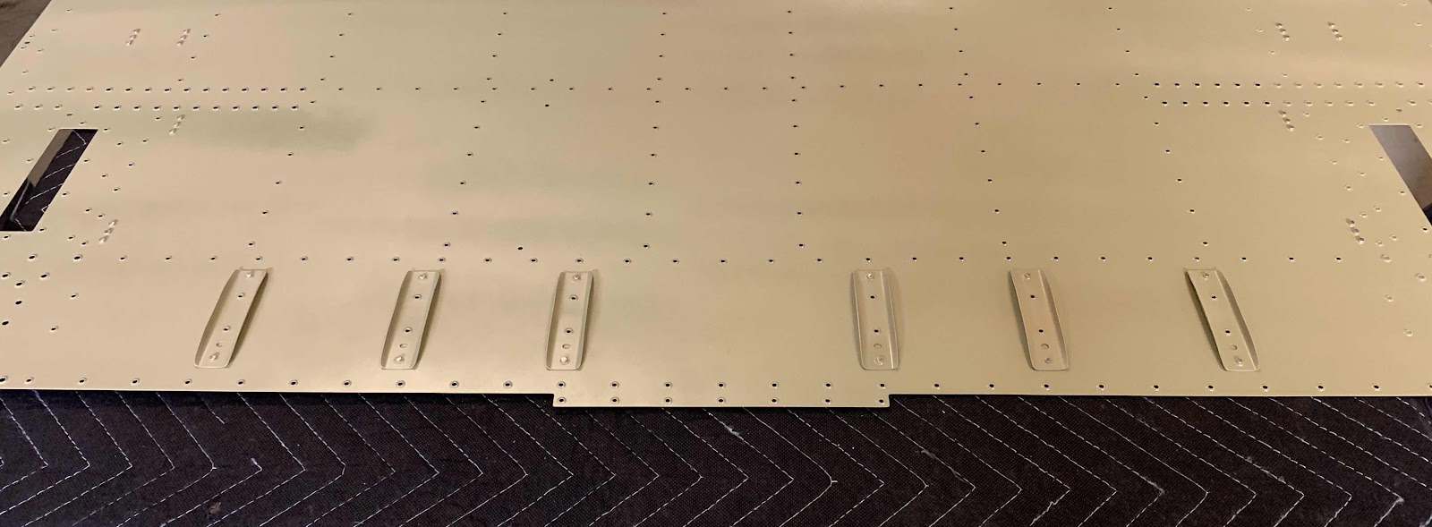
Here is the completed Top Skin. The eight A-710 Stiffeners are attached to the Skin with AN426AD3-3.5 rivets.  The plans called for these rivets to be AN426AD3-3, but they measured a little short.  The 3.5’s measured perfectly, so I decided to use them instead.  I also used 3.5’s to attach the inboard and outboard Main Ribs. 

Below is the Bottom Skin.  It also has eight A-710 Stiffeners and two Main Ribs attached with AN426AD3-3.5 rivets.  If you notice, the Top and Bottom Skins have an area on the trailing edge that was not Akzo primed.  This is the area that the V-Channel will be attached to the Skins and the plans advised to not prime these areas.

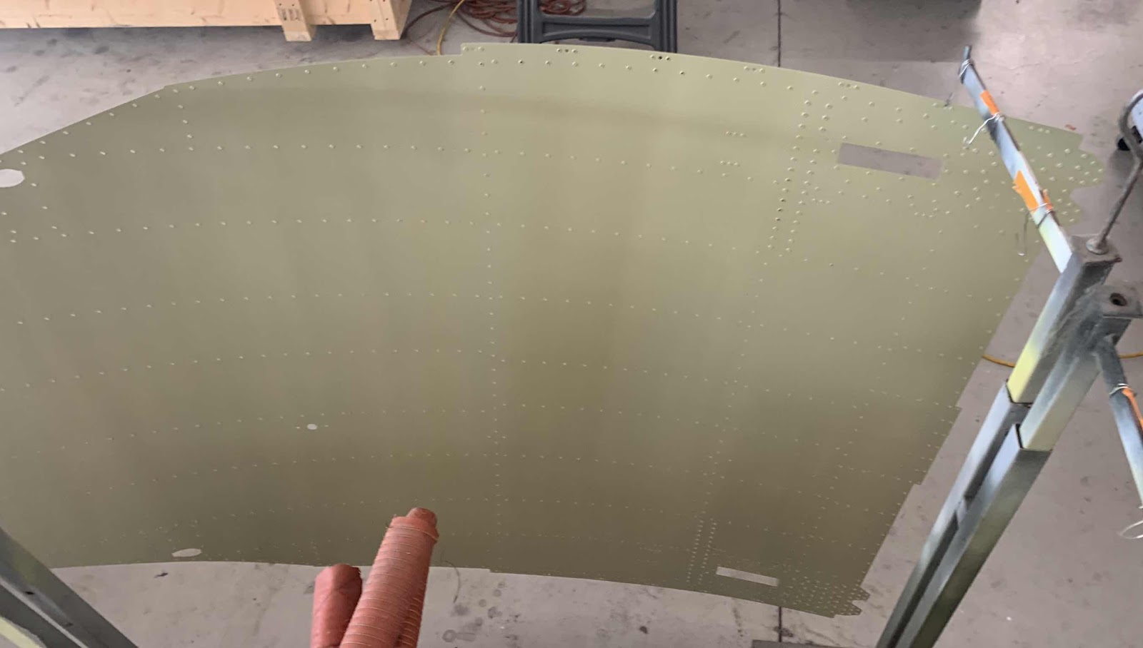
The next step was to cleco the entire Aileron together.  Here is the aft side of the Right Aileron.....

.....the forward side.....

.....the Inboard Hinge Bracket.....

.....Outboard Hinge Bracket.....

.....and the Left and Right Ailerons together (the left is at the top of the photo and the right is at the bottom).

During the next session, I will follow the directions in the plans to determine if the Nose Skins have any “bowing”.  Once that is complete, I will disassemble both Ailerons and Akzo prime the Spars.  Lastly, the Nose Skin will need to be treated with Alumiprep, Alodine, and Akzo primer.....

.....then both Ailerons get riveted together!


Saturday, June 1, 2019

Wings, Ailerons (Part 21)

In Part 20, I prepared several parts and pieces for the Right Aileron.....separated parts, deburred holes, cleaned the edges, and dimpled and/or countersunk the appropriate holes.....

During today’s session, I treated those parts with Alumiprep, Alodine, and Akzo prime.  Below are all the completed parts.  Shown below:

1.  Top and Bottom Skins (with trailing edge not primed for the V-Channel)
2.  A-710 Stiffeners (x16)
3.  A-1006-1B and -1A Outboard Hinge Brackets
4.  A-1007-1A and -1B and -1C Inboard Hinge Brackets
5.  A-1008-1 Doubler
6.  A-1004-1 Nose Ribs (x2)
7.  A-1015-1L Nose Rib
8.  A-1005A-1L and -1R Main Ribs
9.  A-1005B-1L and -1R Main Ribs

Shown below is the new Nose Skin I ordered from Van’s for the Right Aileron (still with blue protective plastic) and the Aileron Counterbalance (I was able to jack from the previous Aileron I messed up)!
Lastly, here is the Spar for the Right Aileron.....all prepped, cleaned and treated with Alumiprep and Alodine.  It is now ready for Akzo prime.

Friday, May 31, 2019

Wings, Ailerons (Part 20)

Prepared several parts and pieces during this session.  Once I completed that, I started clecoing the flaps together for the next session.


Thursday, May 30, 2019

Fuselage, MID Lower Structure (Part 21)

During the last work session, I riveted the Aft Gear Brace Assembly to the Center Bottom Skin.  Today, I will rivet the F-01416B-L & -R Seat Rib Angles.  Below is the right side of the Assembly showing the manufactured heads of the single AN470AD4-7 rivet (on the top) and the two AN470AD4-8 rivets on the bottom.

Here is the aft right side showing the shop heads.....

.....left forward side manufactured heads.....

.....left aft side shop heads.

Prior to riveting the Angles to the Aft Gear Braced Assembly, the plans advised to make sure the F-01416B Seat Rib Angles and the F-01415A Seat Rib Angles are parallel with one another.  To do this, I used a ruler to verify the same measurements at the top and bottom of the Angles.  The lower measurement is 9 7/8” as shown below.....

.....and 9 7/8” at the top. Once those measurements were made, the Angles were clamped to the Assembly, one of the rivets was partially set, re-checked the measurement, and then completely set the rivet.  I completed the same process for the remaining two rivets.

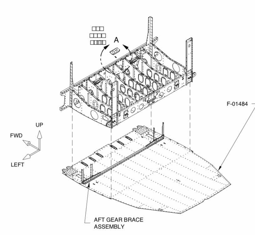
After this was completed, the F-01404 Bulkhead was clecoed to the F-01484 Center Bottom Skin as shown in the plans excerpt below.
This is what it looks like.....


Wednesday, May 29, 2019

Fuselage, MID Lower Structure (Part 20)

Shown below is the final assembly of the Aft Gear Brace Assembly.  There are four parts that make up the Assembly:  

1.  F-01448A Gear Brace Angle
2.  F-01448B Gear Brace Bar
3.  F-01448C Gear Brace Brackets
4.  F-01415A Seat Rib Angles

The Assembly was first clecoed together to allow several holes to be #30 final-drilled, 1/8 final-drilled, dimpled #30, and countersunk. Once all that was completed, the Assembly was riveted together using a mixture of AN470AD4-7 and AN426AD4-7 rivets.  Here is the forward side of the Assembly showing the manufactured heads.....

.....and the aft side showing the shop head side of the rivets.  The rivets were very easily set using my pneumatic squeezer and produced perfect results.

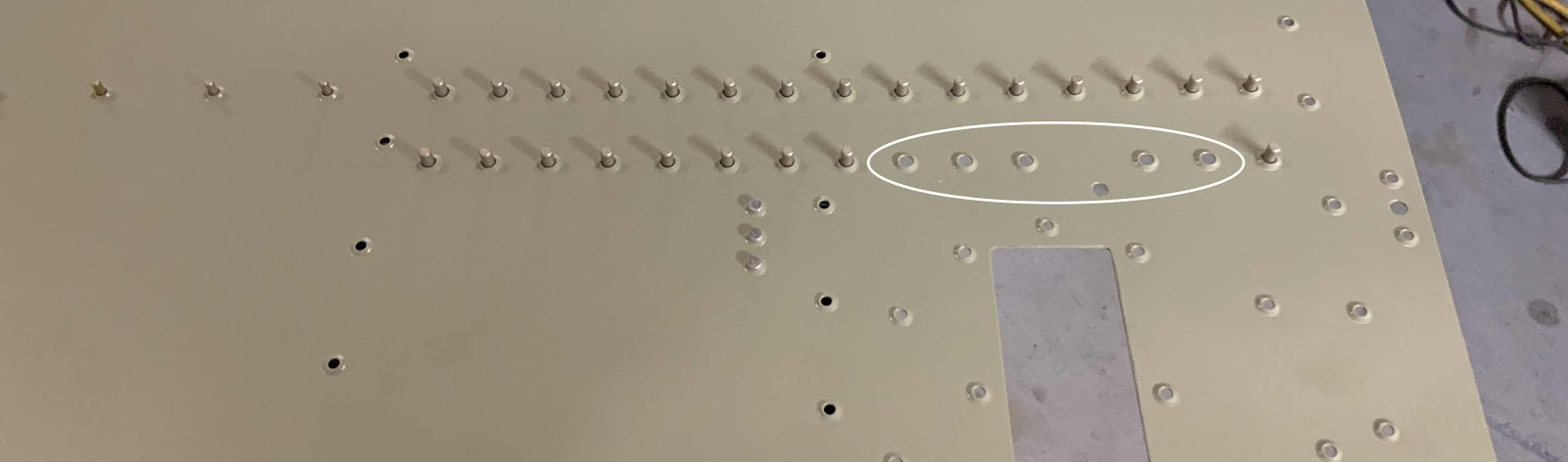
The Aft Gear Brace Assembly will be attached/riveted to the Center Bottom Skin as shown in the picture below.  (The holes in the white circle will not be riveted at this time).  I’ve inserted all the AN426AD4-4 into the appropriate holes and taped them in place.  Here is a close up of what it looks like.

And here is an overview with both sides.

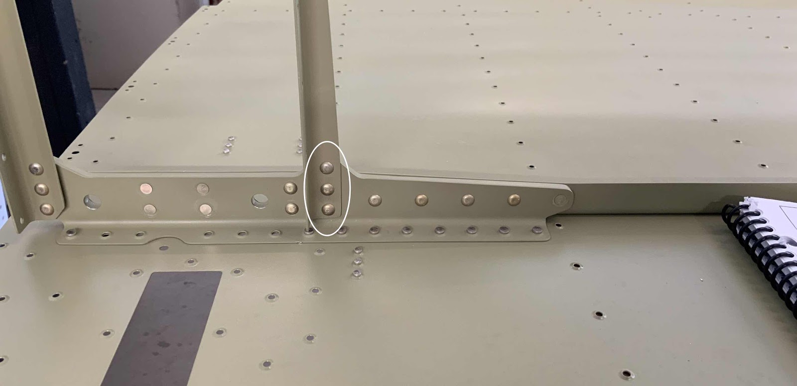
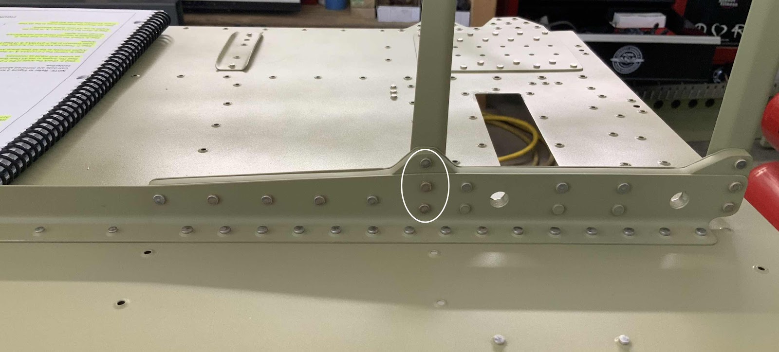
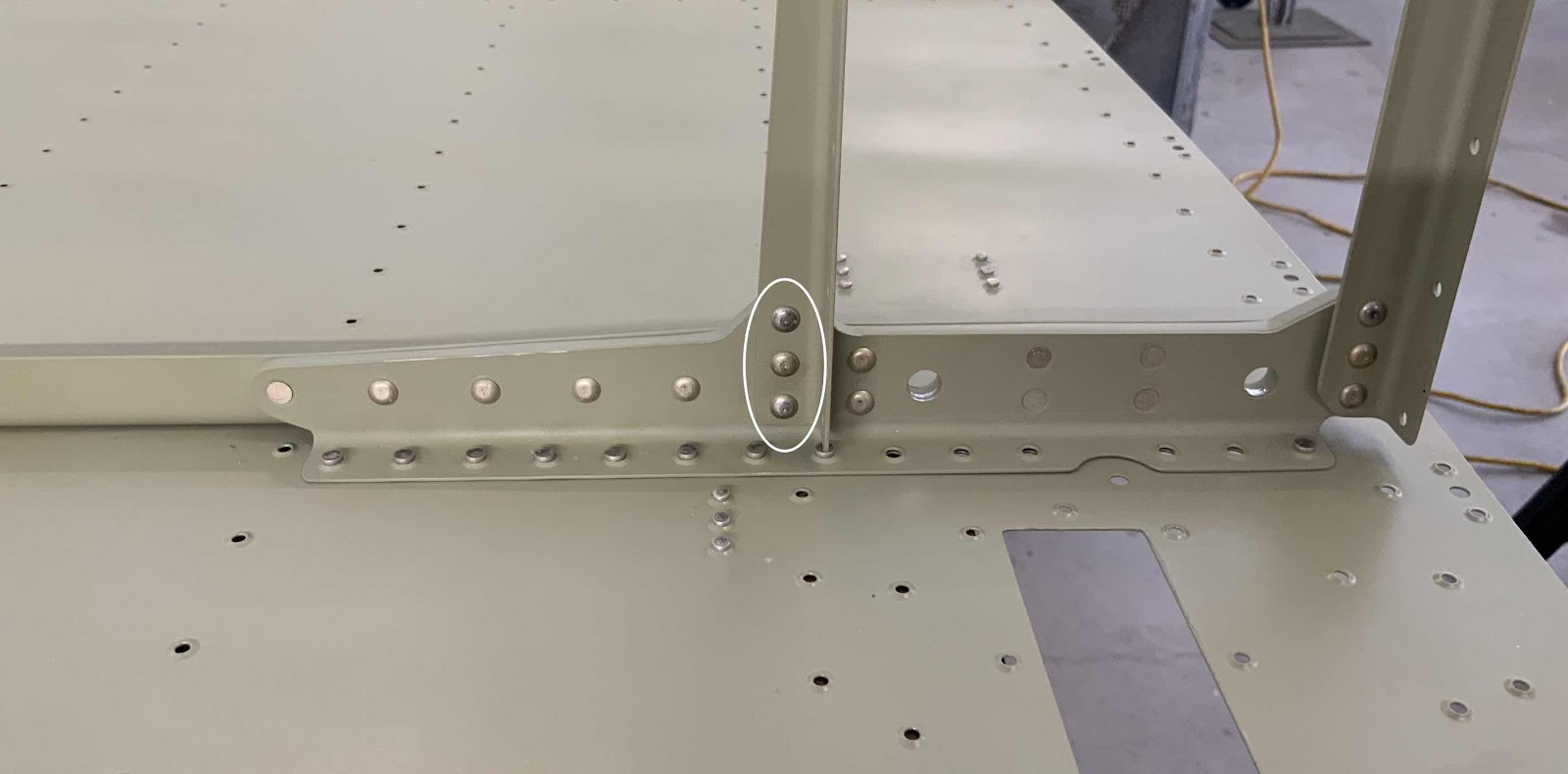
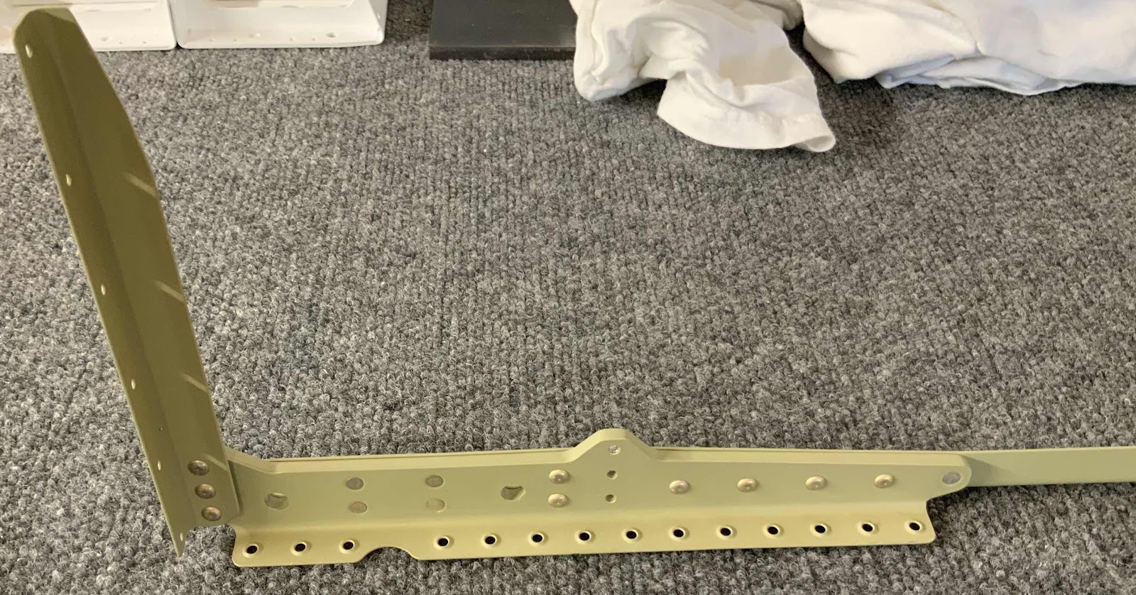
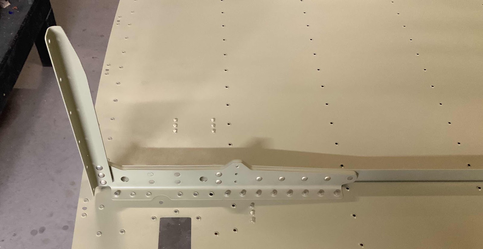
The Aft Gear Brace Assembly was put into place on the rivets shown above.  I backriveted the Assembly to the Skin and the rivets turned out perfect.  Here is the completed forward right side.....

.....aft right side.....

.....completed forward left side.....

.....and aft left side.


Monday, May 27, 2019

Fuselage, MID Lower Structure (Part 19)

After being treated with Alumiprep and Alodine, all the parts prepared in the previous three Parts were sprayed with Akzo primer.

These are the six F-14140 Skin Stiffeners.....

.....F-01443-L &-R Center Section Lower Doublers.....

.....F-14145 Step Attach Angles.....

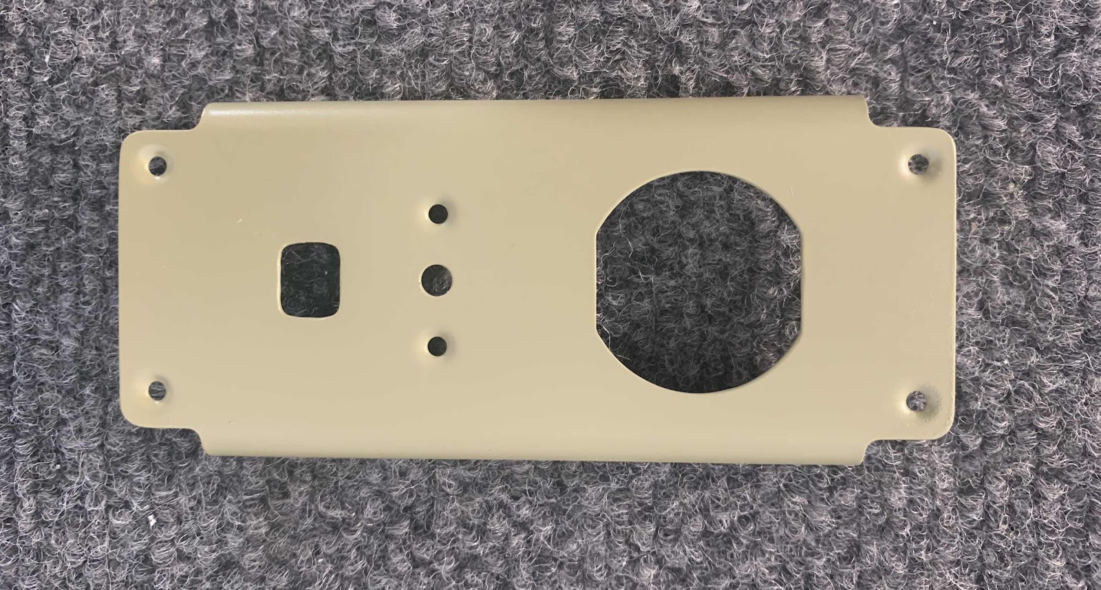
.....F-14123 Power Outlet Bracket.....

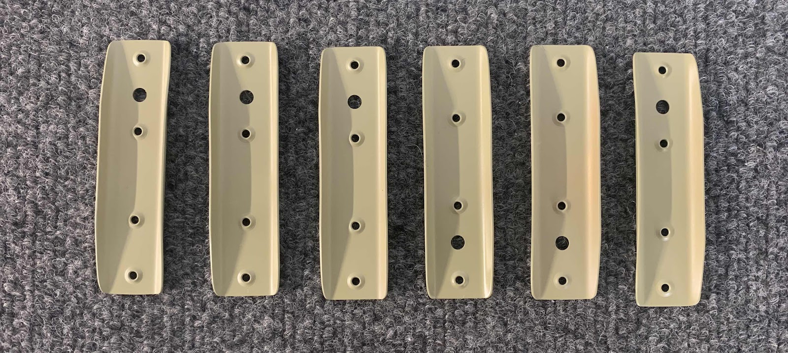
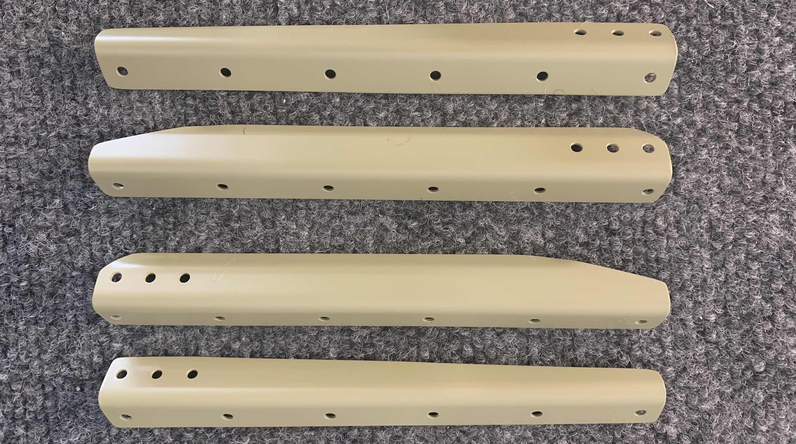
.....two F-01415A-L &-R and two F-01416B-L &-R Seat Rib Angles.....

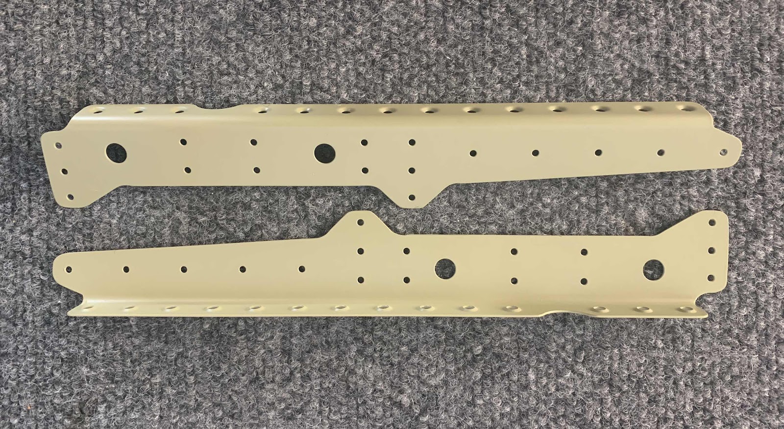
.....F-01448B-L & - R Gear Brace Bars.....

.....F-01448C -L & -R Gear Brace Brackets.....

.....F-01448A Gear Brace Angle.....

.....Bottom side (outside) of the F-01484 Center Bottom Skin.....

.....and the top (inside) of the Center Bottom Skin.

The Power Outlet Bracket received one single K1000-08D nutplate installed with two AN426AD3-3.5 rivets.

And then was installed between the two Inboard Seat Ribs as shown below with four AN425AD3-3.5 rivets.

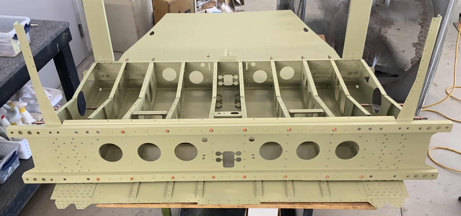
Now, for the taildragger model, there are several locations that only get rivets installed in the hole with no parts attached to it.  These locations are used to install parts for the tri-gear model, but are not needed for the taildragger.  In the picture below, you can see four of those locations (they are the only holes with rivets in them).

Next, the six Skin Stiffeners were riveted to the Center Bottom Skin using AN426AD3-3.5 rivets.  (The plans called for 3-3 rivets, but they measured a little short.  The 3-3.5 rivets measured perfectly).

This is the bottom (outside) of the Center Bottom Skins showing the manufactured heads of the the AN426AD4-5 rivets attaching the Center Section Lower Doublers. This is the left side.....

.....and the right side.

This the right side showing the shop head side of the rivets and the associated Doubler.....

.....and the left side.

Here is an overall view of the Center Section Bottom Skin showing the six Skin Stiffeners and two Doublers.