
Continuing from yesterday’s session, it’s now time to rivet stuff together. Pictured below is the A-1005A-1R Main Rib. In the first picture, you can see the manufactured side of the four AN426AD4-4 rivets attaching the A-10071B Inboard Hinge Bracket to the Main Rib and the manufactured head of the three AN426AD3-4.5 rivets attaching the A-1007-1C Hinge Bracket to the A-1007-1C Hinge Bracket.
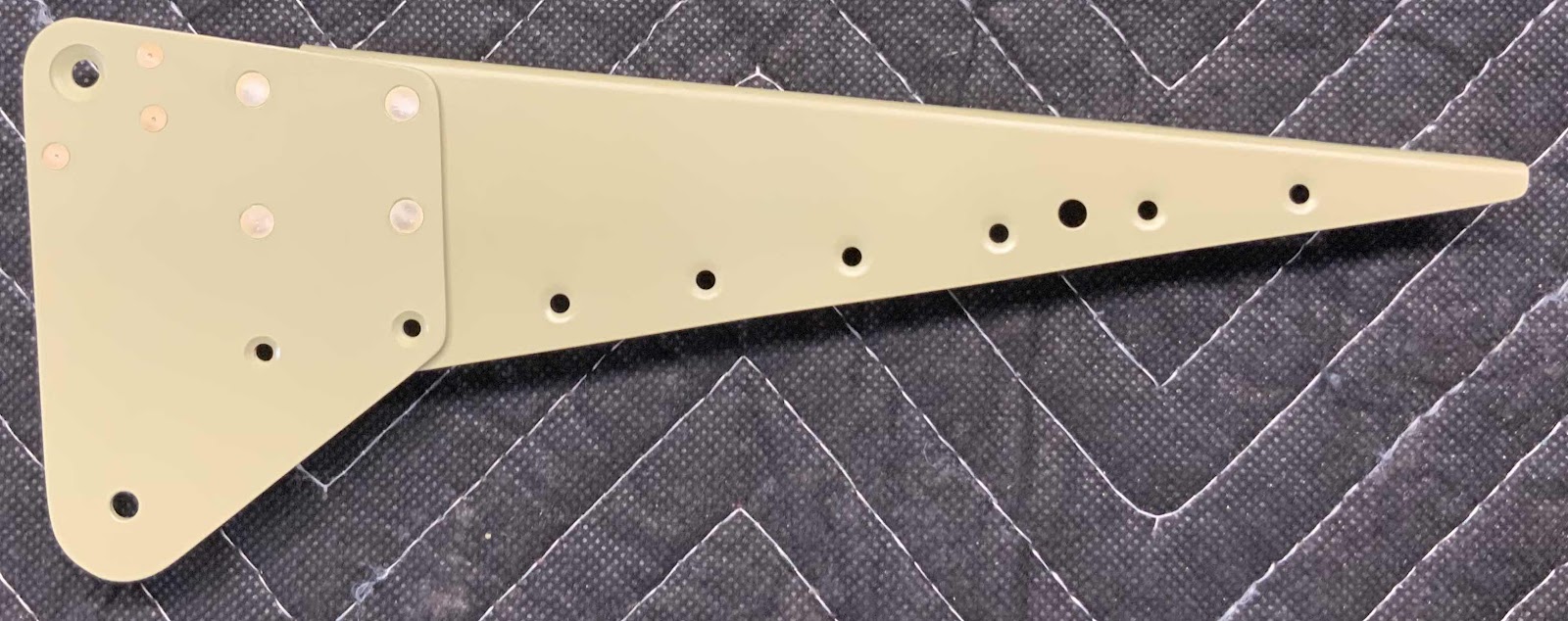
This is the opposite side of the picture above showing the shop head side of the rivets.

This is the A-1005-1L Main Rib with the A-1006-1B Outboard Hinge Bracket riveted together using four AN426AD4-4 rivets. This picture shows the manufactured heads.....

.....and the shop heads on the opposite side.

Here is the A-1004-1L Nose Rib with the A-1006-1A Outboard Hinge Bracket rivet into place using four AN-426AD4-4 rivets.
This is the opposite side of the picture above showing the shop head side of the rivets.

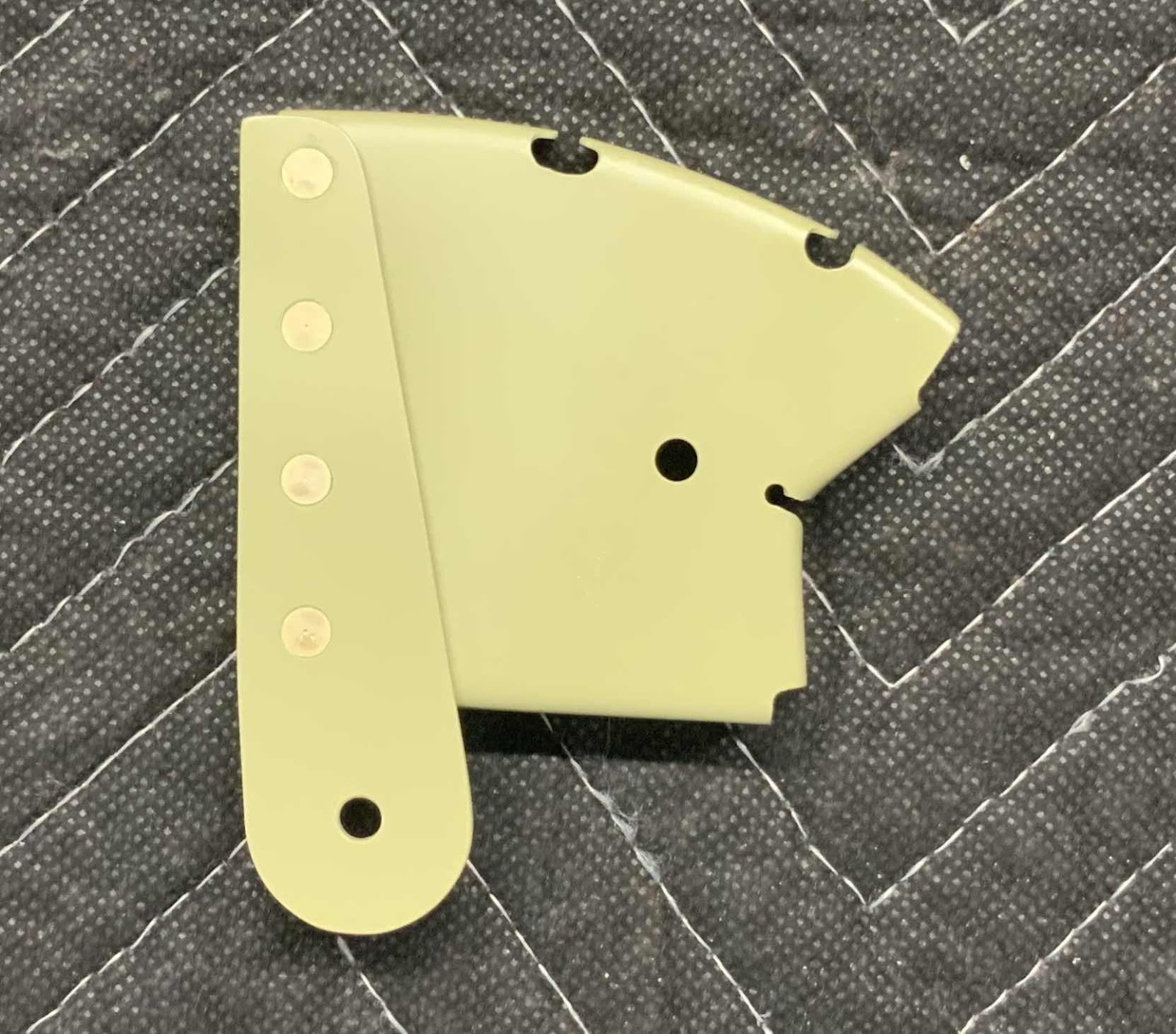
The A-1015-1R Rib with the A-1007-1A Inboard Hinge Bracket riveted into place using six AN426AD4-4 and two AN426AD3-4.5 rivets.
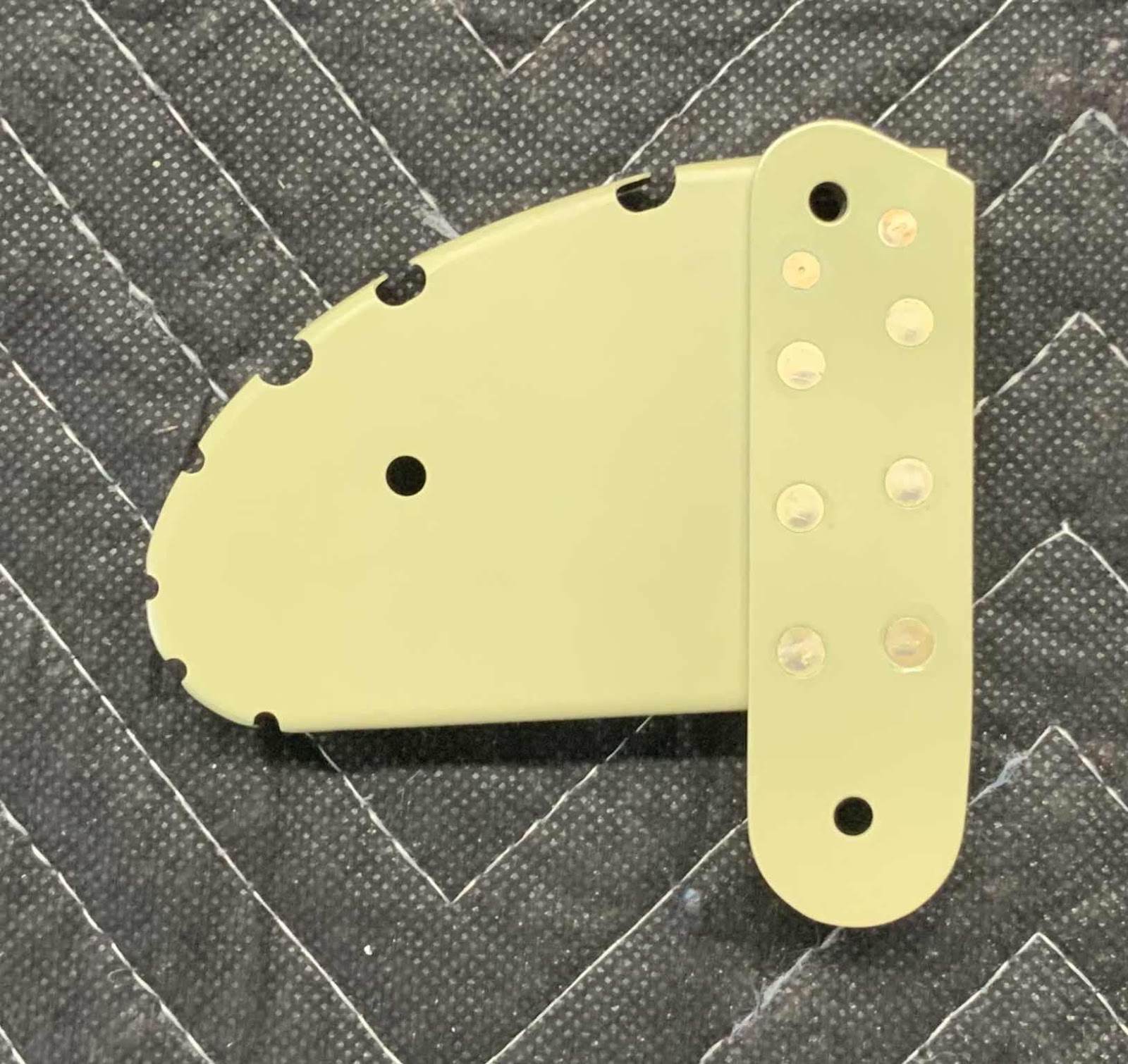
This is the opposite side of the picture above showing the shop head side of the rivets and the single MS21055-L3 nutplate.

Here is the completed Top Skin. The eight A-710 Stiffeners are attached to the Skin with AN426AD3-3.5 rivets. The plans called for these rivets to be AN426AD3-3, but they measured a little short. The 3.5’s measured perfectly, so I decided to use them instead. I also used 3.5’s to attach the inboard and outboard Main Ribs.

Below is the Bottom Skin. It also has eight A-710 Stiffeners and two Main Ribs attached with AN426AD3-3.5 rivets. If you notice, the Top and Bottom Skins have an area on the trailing edge that was not Akzo primed. This is the area that the V-Channel will be attached to the Skins and the plans advised to not prime these areas.

The next step was to cleco the entire Aileron together. Here is the aft side of the Right Aileron.....

.....the forward side.....

.....the Inboard Hinge Bracket.....

.....Outboard Hinge Bracket.....

.....and the Left and Right Ailerons together (the left is at the top of the photo and the right is at the bottom).

During the next session, I will follow the directions in the plans to determine if the Nose Skins have any “bowing”. Once that is complete, I will disassemble both Ailerons and Akzo prime the Spars. Lastly, the Nose Skin will need to be treated with Alumiprep, Alodine, and Akzo primer.....
.....then both Ailerons get riveted together!