After being treated with Alumiprep and Alodine, all the parts prepared in the previous three Parts were sprayed with Akzo primer.
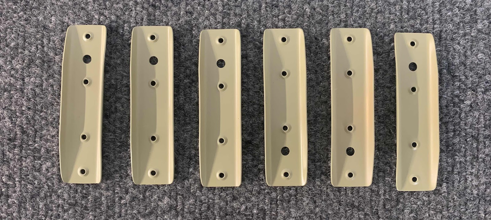
These are the six F-14140 Skin Stiffeners.....
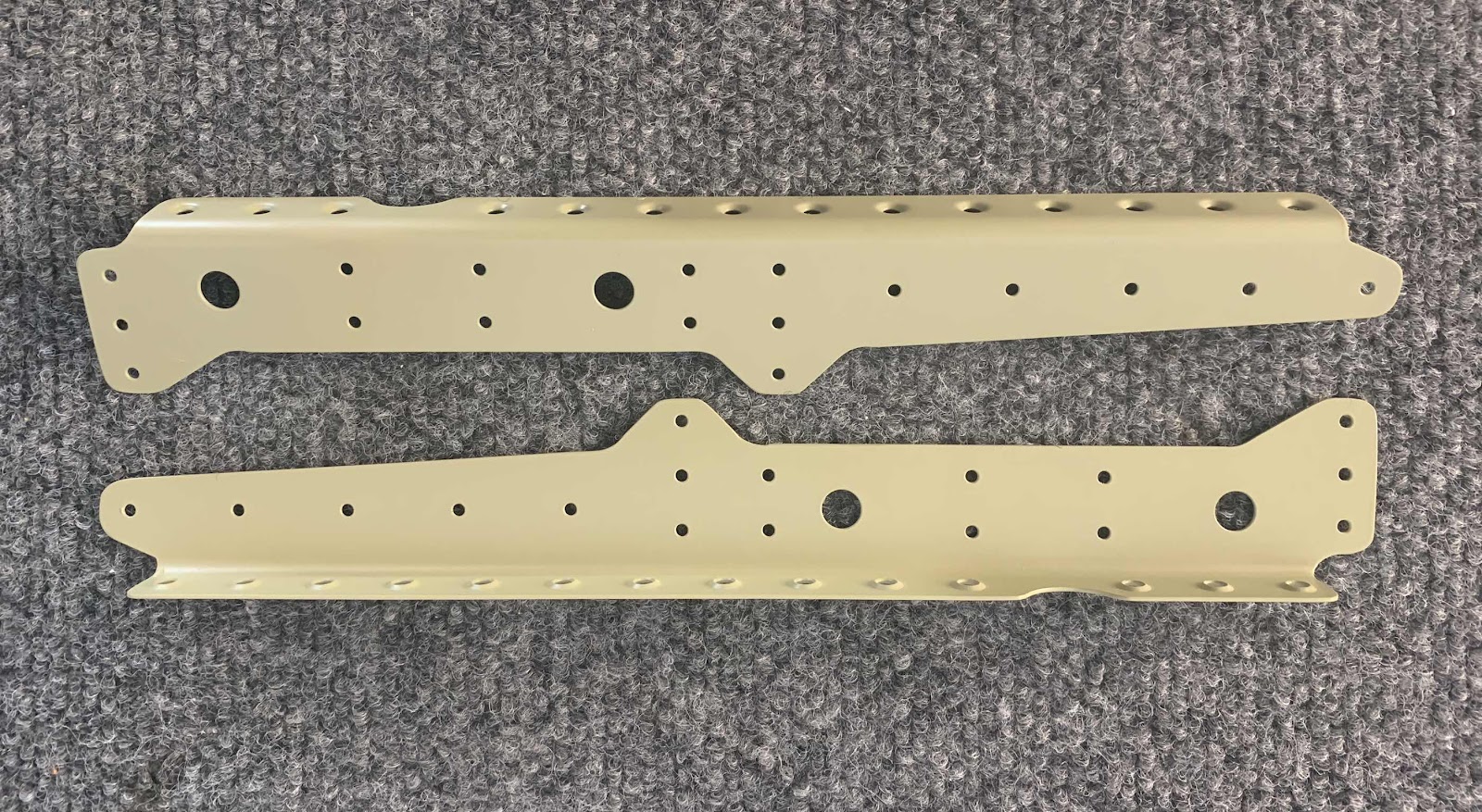
.....F-01443-L &-R Center Section Lower Doublers.....

.....F-14145 Step Attach Angles.....

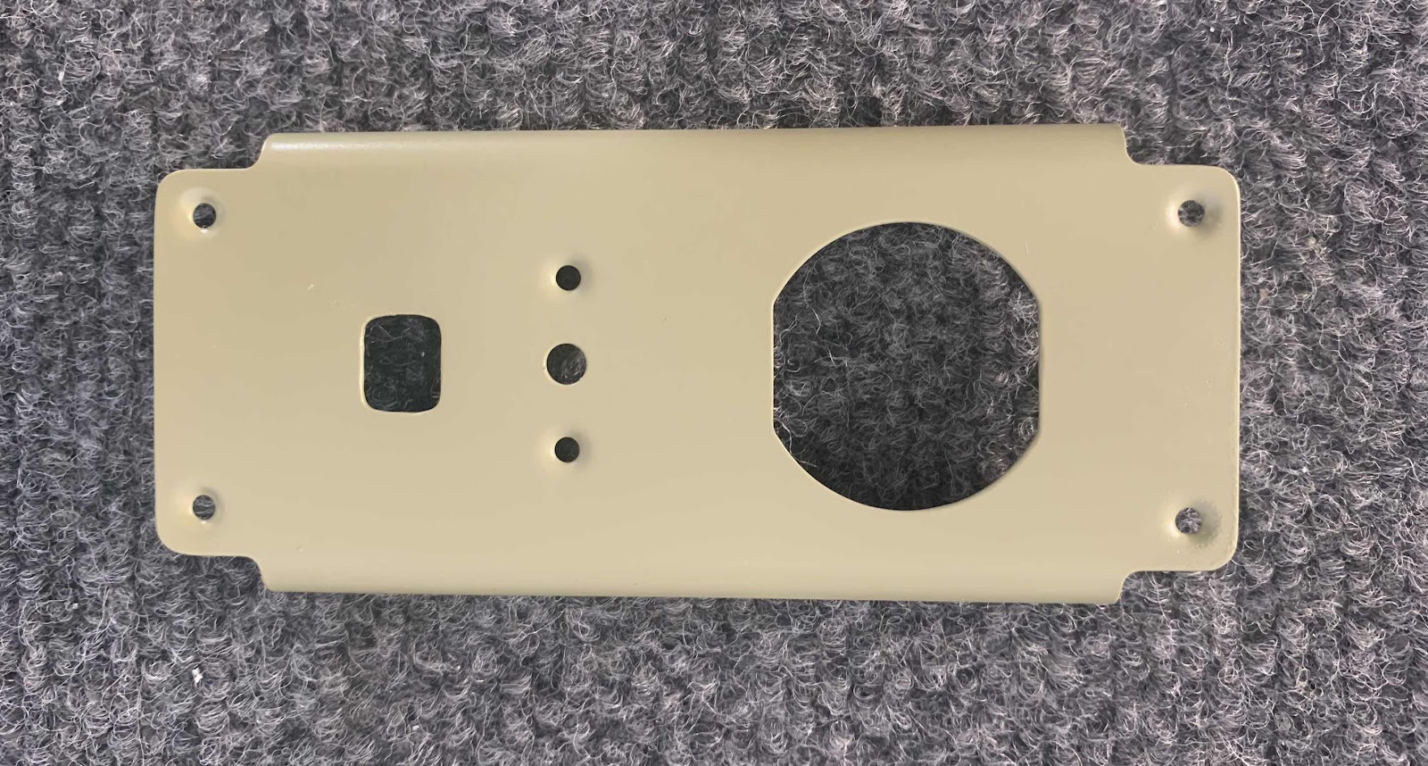
.....F-14123 Power Outlet Bracket.....
.....two F-01415A-L &-R and two F-01416B-L &-R Seat Rib Angles.....
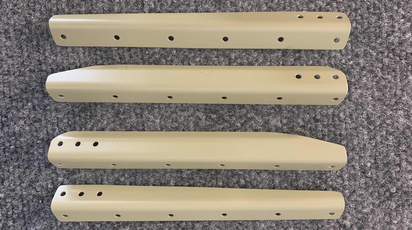
.....F-01448B-L & - R Gear Brace Bars.....

.....F-01448C -L & -R Gear Brace Brackets.....
.....F-01448A Gear Brace Angle.....

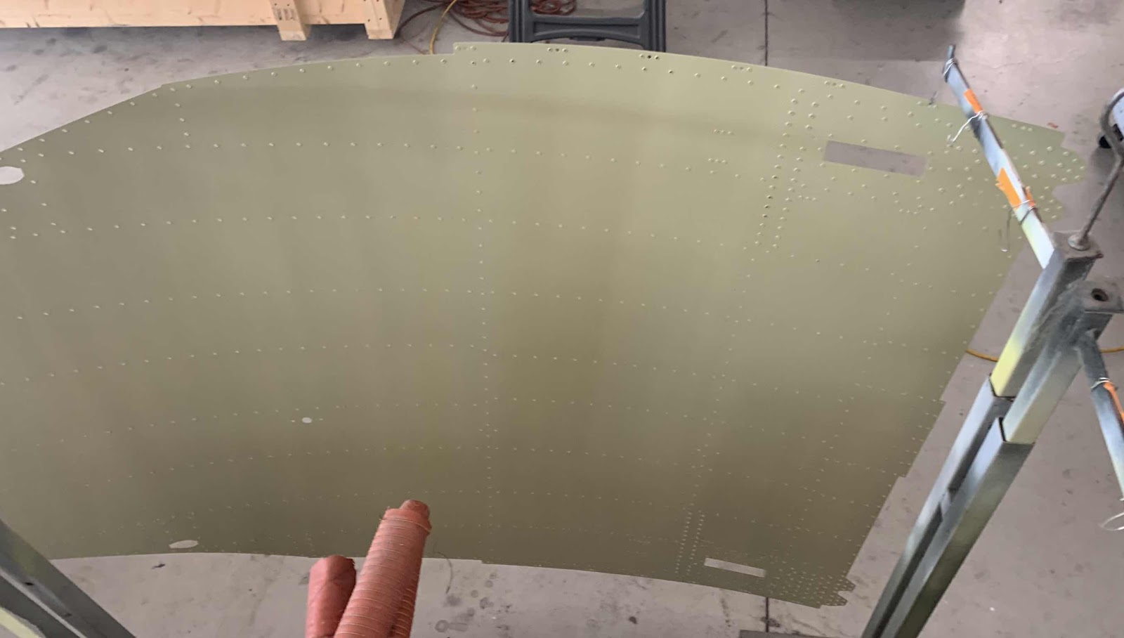
.....Bottom side (outside) of the F-01484 Center Bottom Skin.....

.....and the top (inside) of the Center Bottom Skin.
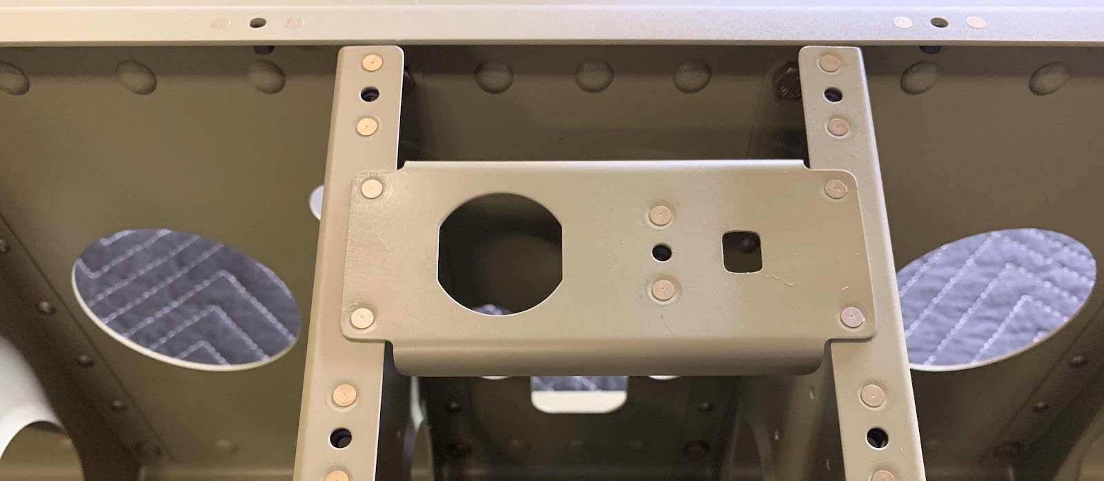
The Power Outlet Bracket received one single K1000-08D nutplate installed with two AN426AD3-3.5 rivets.

And then was installed between the two Inboard Seat Ribs as shown below with four AN425AD3-3.5 rivets.
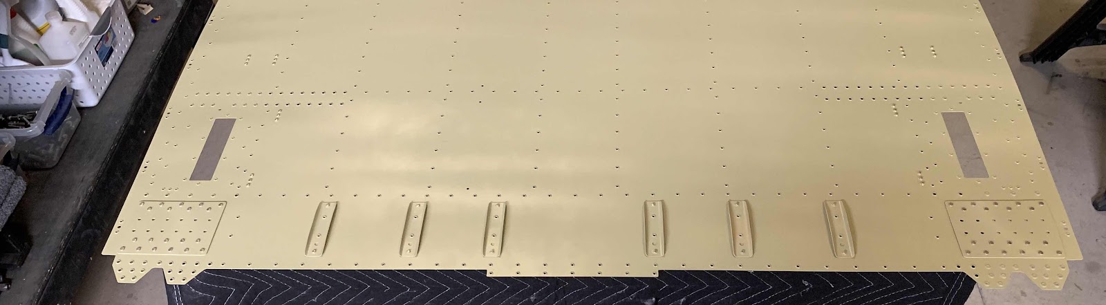
Now, for the taildragger model, there are several locations that only get rivets installed in the hole with no parts attached to it. These locations are used to install parts for the tri-gear model, but are not needed for the taildragger. In the picture below, you can see four of those locations (they are the only holes with rivets in them).

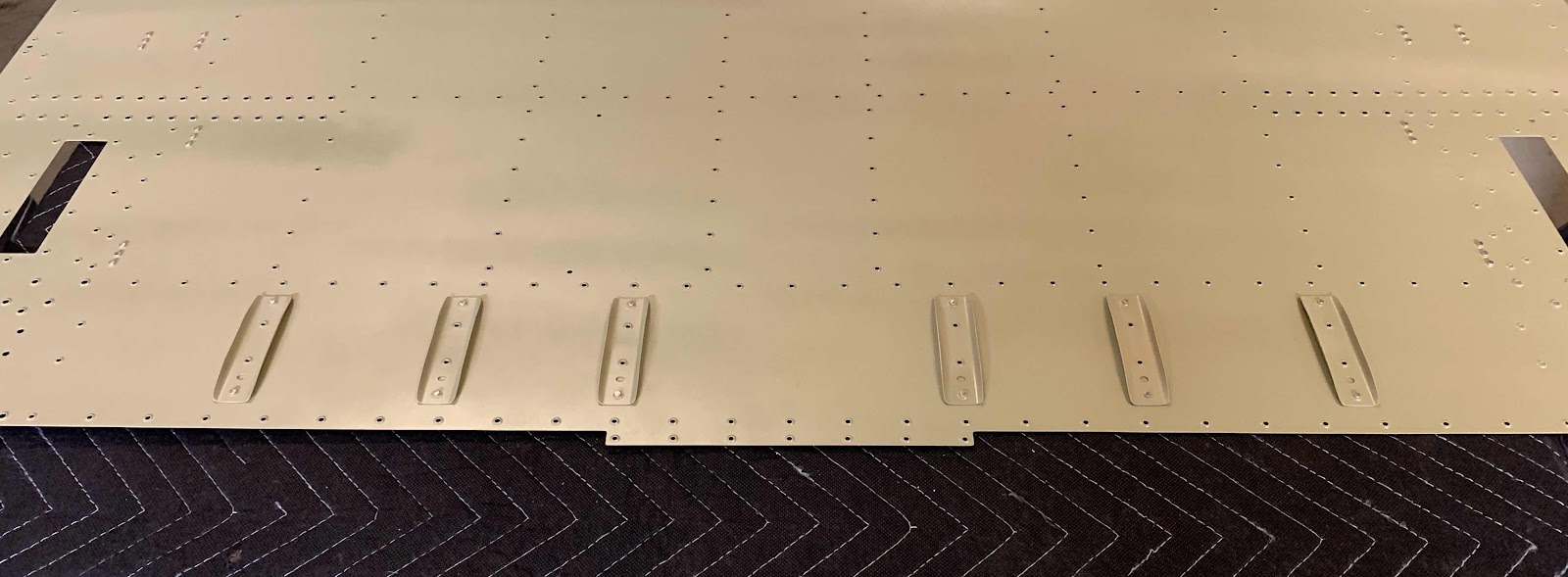
Next, the six Skin Stiffeners were riveted to the Center Bottom Skin using AN426AD3-3.5 rivets. (The plans called for 3-3 rivets, but they measured a little short. The 3-3.5 rivets measured perfectly).
This is the bottom (outside) of the Center Bottom Skins showing the manufactured heads of the the AN426AD4-5 rivets attaching the Center Section Lower Doublers. This is the left side.....

.....and the right side.

This the right side showing the shop head side of the rivets and the associated Doubler.....

.....and the left side.

Here is an overall view of the Center Section Bottom Skin showing the six Skin Stiffeners and two Doublers.