Thursday, February 20, 2020

Fuselage, Baggage Area (Part 9)

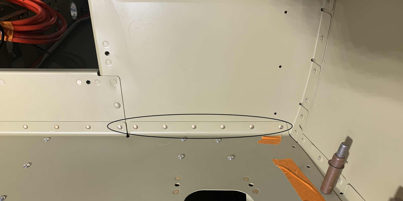
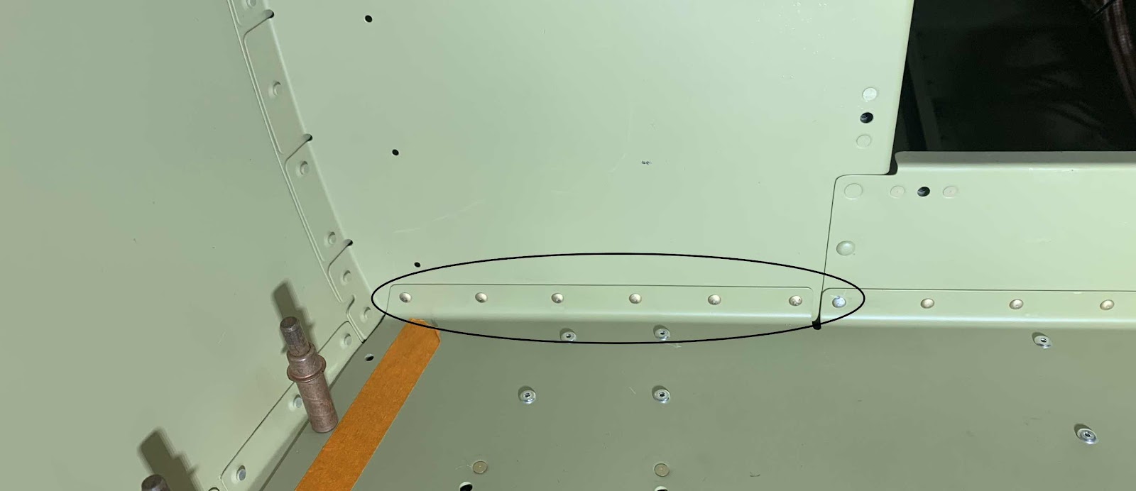
During the last session, I set the “inside” six AN470AD3-3.5 rivets with my hand squeezer.  Today, I shot the seven “outside” rivets circled below.  These rivets connect the F-01447-L & -R Baggage Floors and F-01406A-L & -R Bulkheads.

This is the left side (the rivet to the far left also goes through the F-01406B Bulkhead).....
.....and the right side (also with the far right rivet going through the F-01406B Bulkhead).
The next part to get installed is the F-14141 Baggage Floor Splice.  Here is the plans excerpt showing the install.....
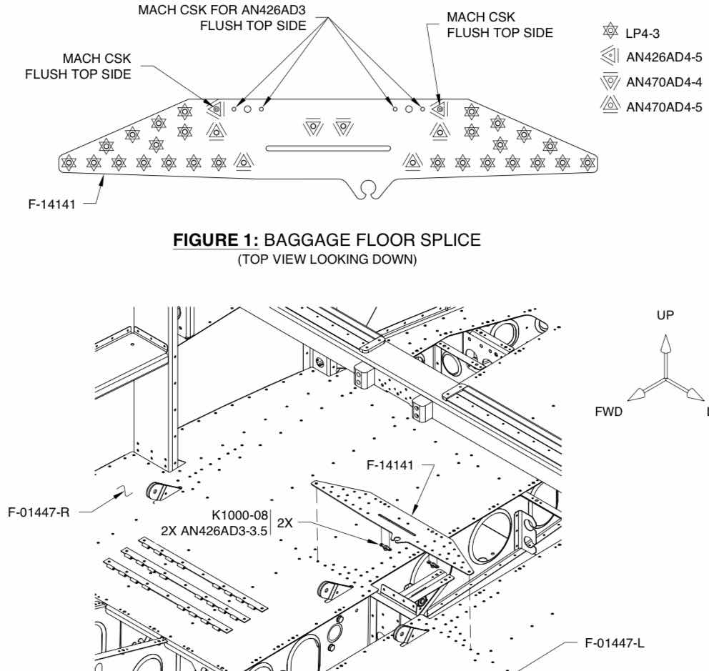

.....and here is the finished install of the Splice.  This is the forward side.....


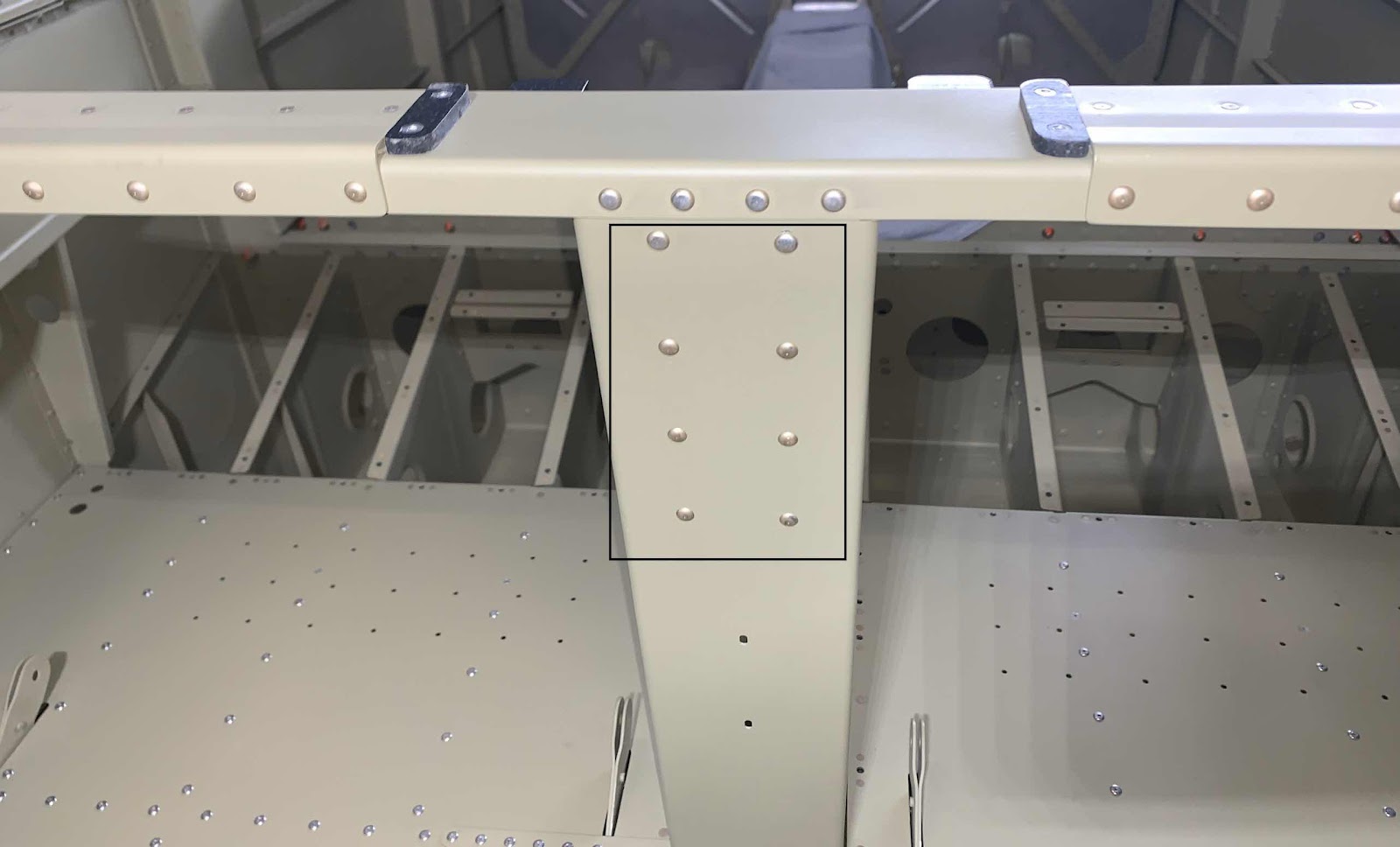
.....and the aft side.  Once the Splice was installed, the F-01405G Flap Motor Channel was installed and riveted to the F-01405F Mid Fuselage Brace (the four rivets boxed in below) and the F-01405L Bulkhead Doubler (clecoed at the bottom, second picture ).
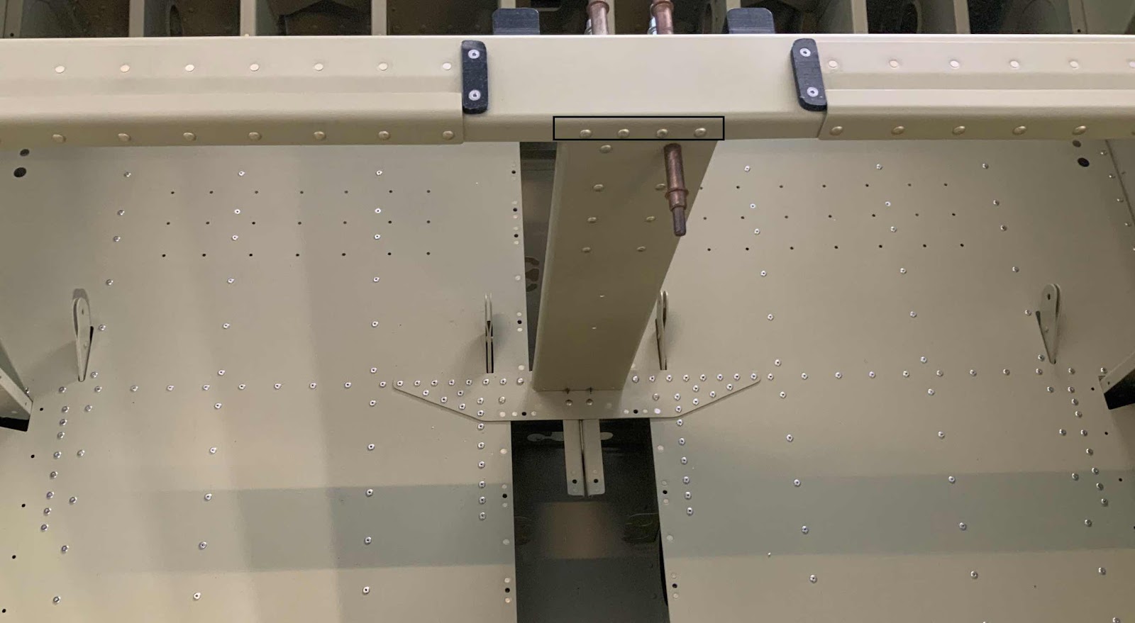
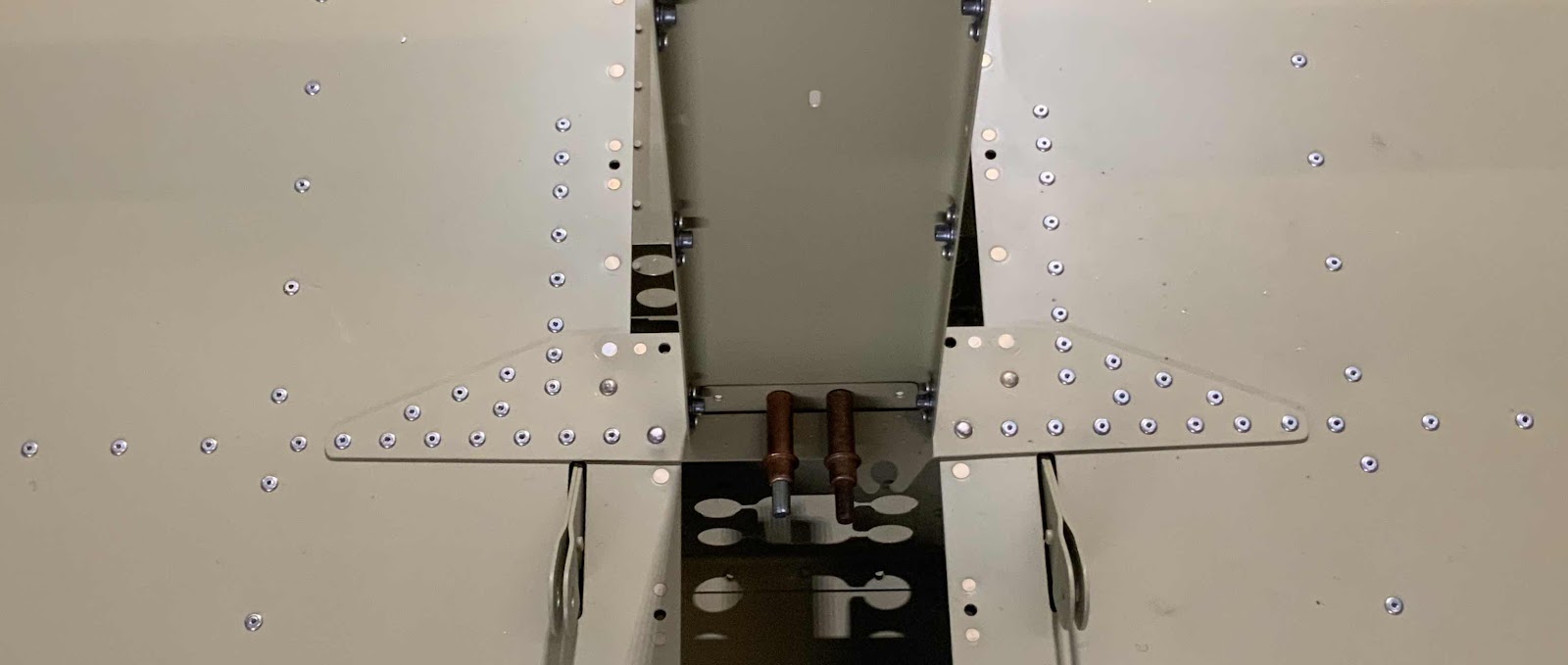

Moving on to the F-01466-L & -R Flap Motor Brackets.  The two Brackets get riveted to the F-01405F Mid Fuselage Brace and F-01405G Flap Motor Channel.  Pictured below is the forward side of the Brackets riveted to the forward portion of the Brace.....
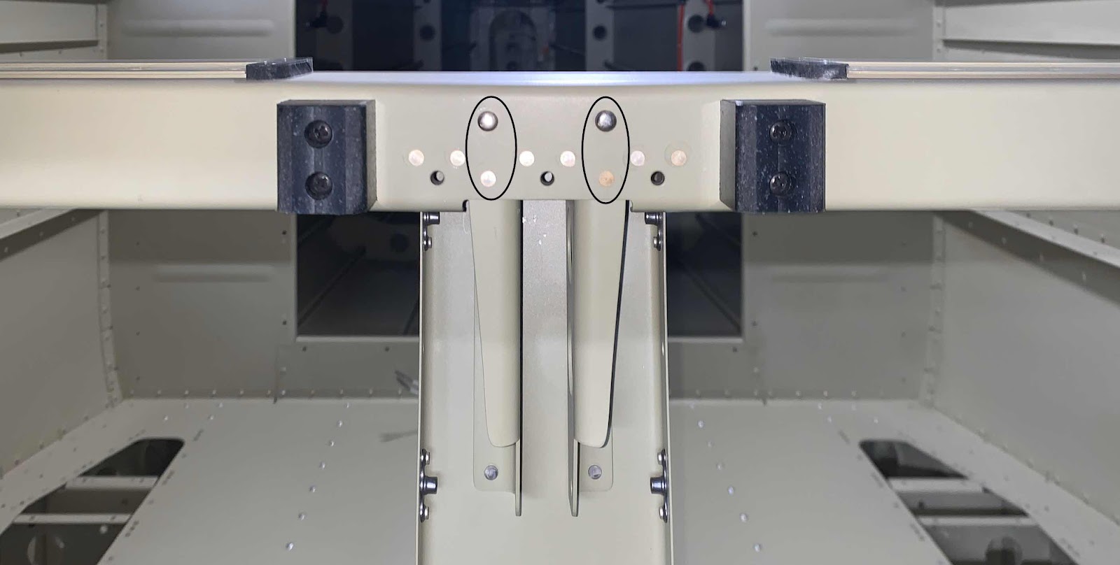
.....and the aft side of the Brackets riveted to the Channel.
Tuesday, February 18, 2020

Fuselage, Baggage Area (Part 8)

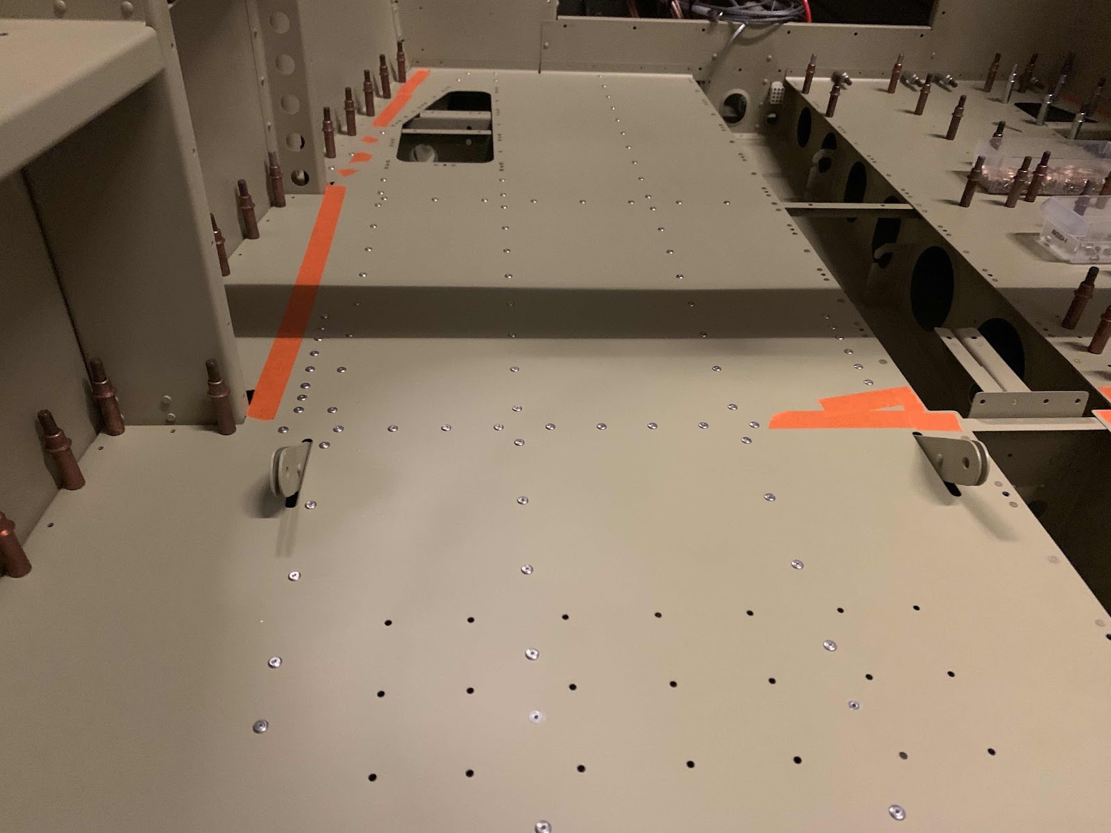
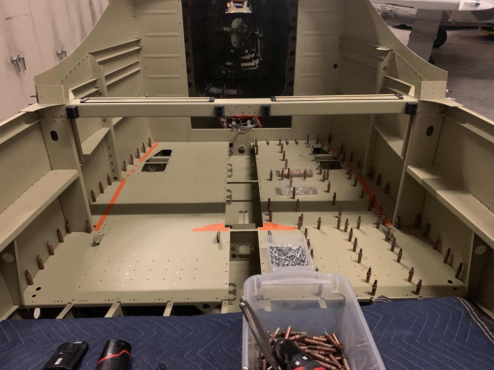
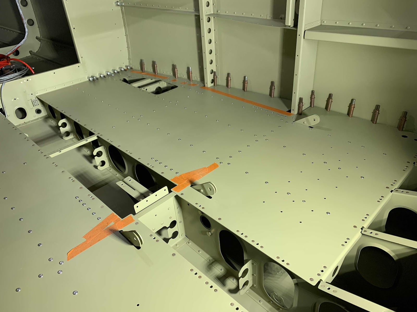
During the last session, we installed the F-01447-R Baggage Floor (minus the most outboard row of LP4-3 rivets).  Tonight, we installed the F-01447-L Baggage Floor (minus the same LP4-3 rivets).  Those outboard rivet locations will be completed in a future step.  The orange tape on both Baggage Floors mark the locations that DO NOT get riveted at this time.

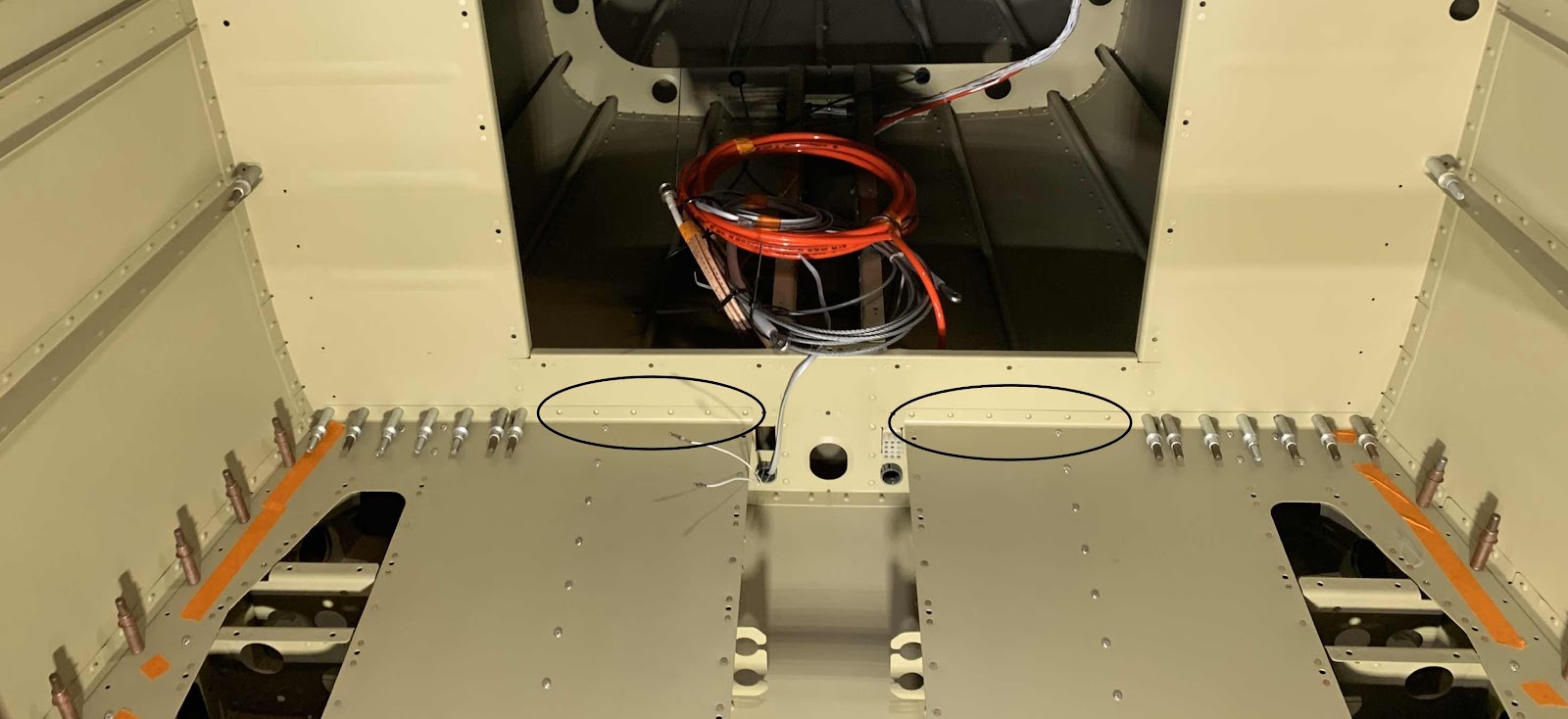
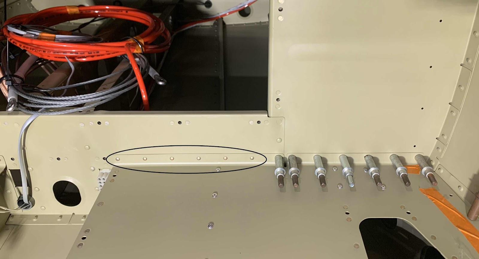
Once the left Baggage Floor was installed, the next step was to rivet the rear flanges of the Baggage Floors to the F-01406A-L & -R and F-01406B Bulkheads in the areas circled below.....as well as, the locations of the #40 silver clecos.  The picture below shows the inside 12 rivets (6 on each side) installed in the flanges and Bulkheads.   The plans called for AN470AD3-3 rivets, but measured a little short.  I used AN470AD3-3.5 rivets as they measured the perfect length.

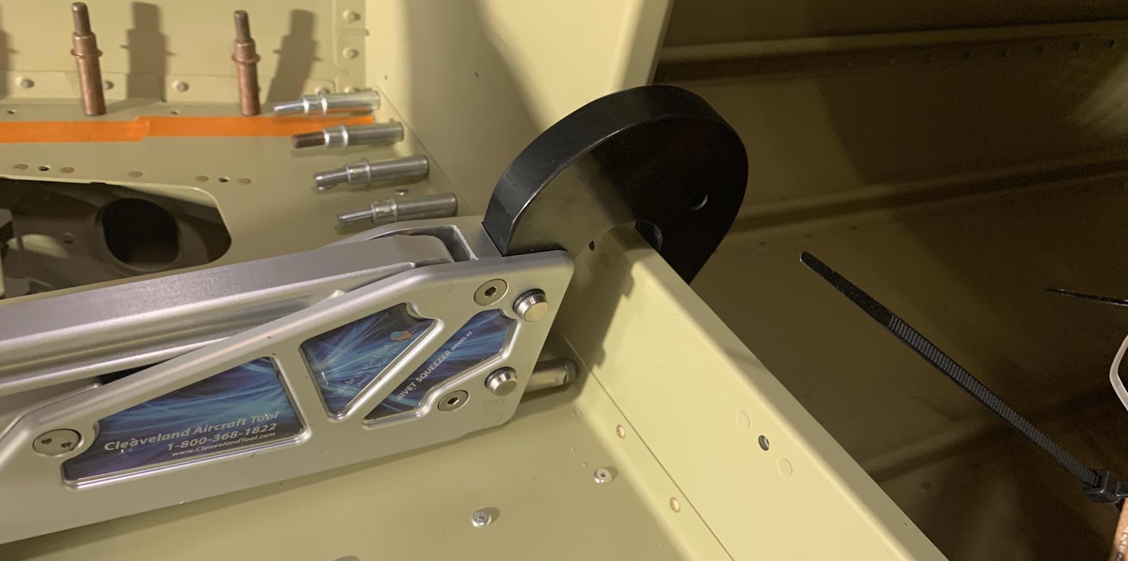
Fortunately, I was able to use my hand squeezer with a 3” yoke to set the 12 rivets discussed above.  Here are a couple of angles showing how the squeezer was able to access the rivets.


These are the six rivets set on the right side.....

.....and the six rivets installed on the left side.  The remaining six rivets on each Baggage Floor flange will have to be shot.....can’t squeeze those ones!

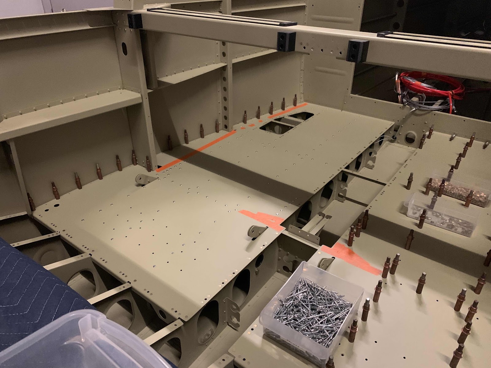
Lastly, here is an overview of the Baggage Area.

Monday, February 17, 2020

Fuselage, Baggage Area (Part 7)

While I was waiting for riveting help with the Aft Fuselage Attachment, I started some of the initial parts prep on a couple of additional Sections.....including the Baggage area.  Those initial steps for the Baggage Area are covered in part 1 - 6 in this section.  Now that the Aft Fuselage Attachment is complete, I turned my attention back to the Baggage Area.  

To begin, prior to installing the F-01447-L & -R Baggage Floors, I prepared the area that would be under the Baggage Floors.  I vacuumed any/all debris, wiped/cleaned with MEK, and let the area dry.  After a few minutes, I took a small airbrush and touched up with Akzo Primer all the areas that the original primer might have been removed....scratched from the bucking bar, parts scratching each other, etc.  Then, ultimately, I decided to just got ahead and Akzo prime ALL the areas that were not previously primed.....mostly the shop head side of rows of rivets.  Anyway, now that all that is complete, it’s time to put down the Baggage Floors.  Both Floors were clecoed into place and for no particular reason, we started on the right side.

A couple of the center holes for nutplates had to be final drilled to #19, but no other preparation was needed (previously completed in Parts 1 - 6).  The Access Panel opening and outside edges of each Baggage Floor contained a total of 30 K1000-08D nutplates, 15 AN426AN4-4 rivets, and four CCR-264SS-3-2 rivets.   All the remaining holes (many of them) received LP4-3 Blind Rivets.  Here is the almost completed right Baggage Floor.....

.....and a close up of the right Baggage Floor.

This is a view showing the right and left Baggage Floors.  The Floor on the left (right Baggage Floor) is almost complete.  The Floor on the right (left Baggage Floor) is clecoed into place and will be completed next.

More to follow during the next session.

Sunday, February 16, 2020

Fuselage, Aft Fuselage Attachment (Part 9)

We continued installing the remaining rivets to complete the Fuselage attachment.  The final 116 were set on the outside and six on the inside.  Here is the complete left side of the airplane.....


.....and overview from aft looking forward.....


.....and right side of the airplane.....DONE!!!!!


Section Complete

Saturday, February 15, 2020

Fuselage, Aft Fuselage Attachment (Part 8)

Take a look at ALL those clecos in the Fuselage in Part 7!!  Today, we swapped out 100 of those cleos for rivets!  According to the plans, we are 116 rivets away from “officially” completing the Aft Fuselage Attachment.  Here is right side of the Fuselage.....

.....the left side of the Fuselage.....

.....and an overview of the Bottom Skins.

More riveting tomorrow.....

Wednesday, February 12, 2020

Fuselage, Aft Fuselage Attachment (Part 7)

Alright, to make it TREMENDOUSLY easier to install the remainder of the Aft Fuselage Attachment rivets (where all the clecos are installed in the two pictures below).....I went and got some dudes.....and we flipped the Fuselage as shown below.  The forward portion of the Fuselage is resting on one of my work tables and the aft portion is resting on one of my sawhorses.  This set up is very stable, sturdy and I like the set up.  Now, the bucker can sit in a rollie chair, in the opening for the baggage compartment area, and have access to ALL the rivet shop heads.  The shooter will also have unrestricted access to all the manufactured heads.


The picture below was taken with me sitting in a rollie chair in the baggage compartment area of the Fuselage.  See all the access the bucker will have to set all the required rivets.

The first eight rivets set (four on each side), in this orientation, are between the F-01406B Bulkhead and F-01406A Bulkheads.  Shown below is the left side and used one AN426AD4-4 and three AN470AD4-4 rivets.....

.....and the right side using the same rivet assortment.

We will continue with rivet installation during the next session.

Sunday, February 9, 2020

Fuselage, Aft Fuselage Attachment (Part 6)

Tonight, we were able to install the rivets (circled below) common to the F-01473-R Aft Fuselage Side Skin and the F-01418-R Aft Fuselage Longeron (along with a few Skin to Skin rivets).

Here are two pictures of the inside, or shop head side, of the rivets installed above.


Here are the rivets installed common to the F-01473-L Aft Fuselage Side Skin and the F-01418-L Aft Fuselage Longeron (also along with a few Skin to Skin rivets).

The next two pictures show the inside, or shop head side, of the rivets installed above.


We will install more rivets during the next work session.....

Friday, February 7, 2020

Fuselage, Rudder and Brake System (Part 6)

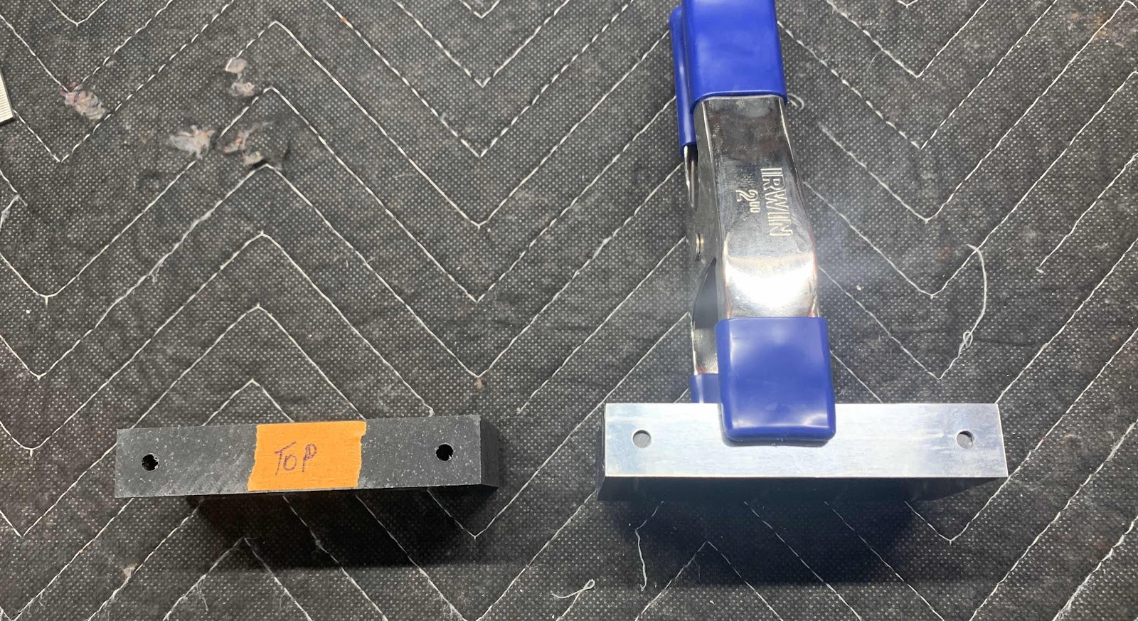
Tonight, I started working on the Bearing Blocks.  There are two F-1039A Rudder Pedal Bearing Blocks and they get prepared the same way.  To start, the aluminum Bearing Block template is clamped to one of the Bearing Blocks and the two guide holes are match-drilled #12 in the Bearing Block about 3mm deep.  In the picture below, the Bearing Block on the right has the template clamped into position and the left one shows the template removed with the two match-drilled #12 holes drilled in the Block.  Lastly, those two holes were final-drilled #10 all the way through the Bearing Block using the drill press.

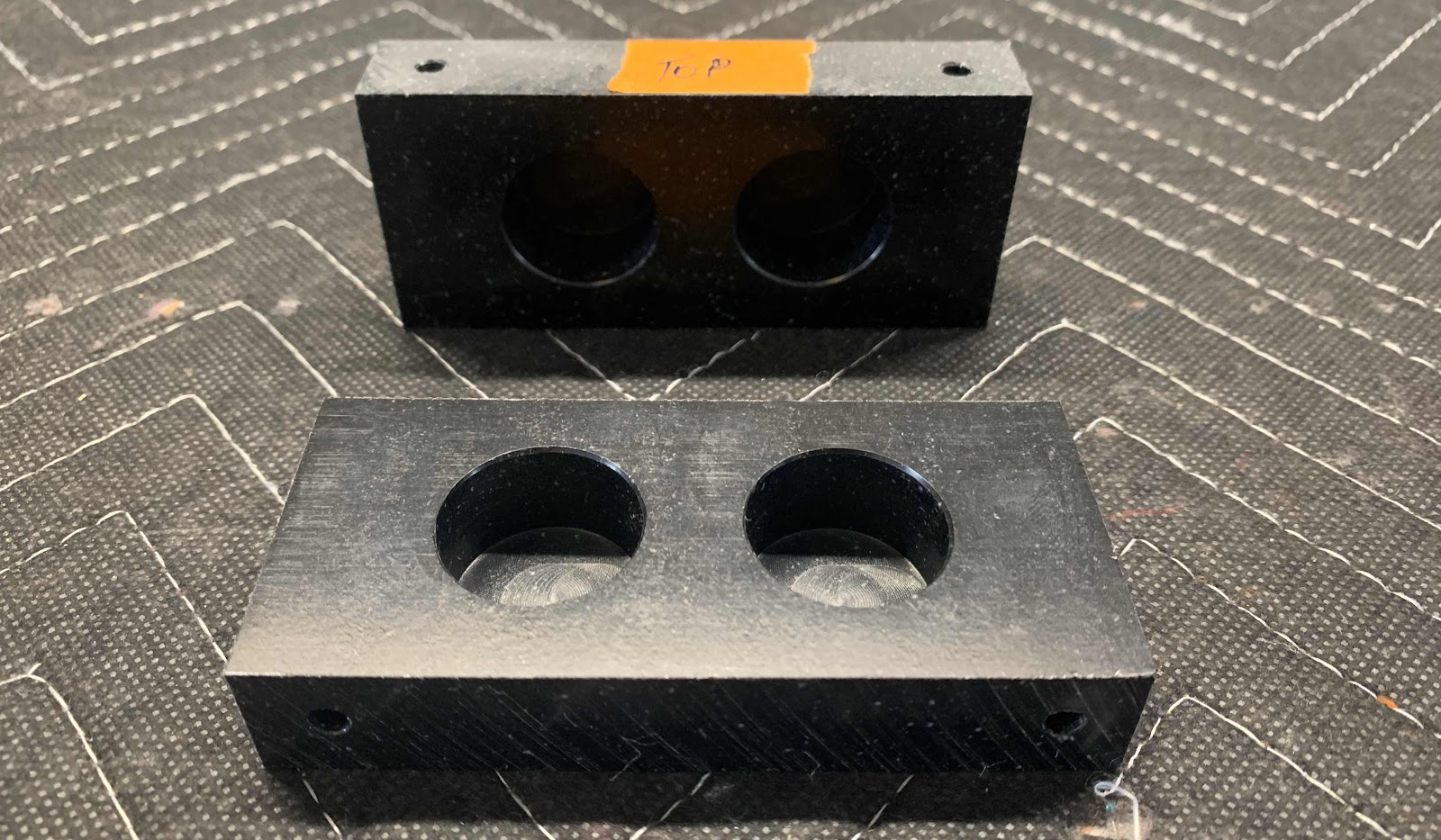
Here are the two completed F-1039A Bearing Blocks.

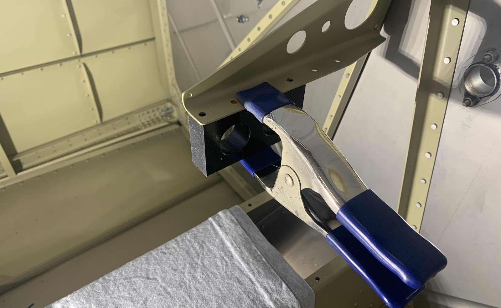
The F-6115 Rudder Pedal Bearing Block was prepared in a similar fashion.  However, instead of using a template as a drill guide, this Block was clamped to the F-14104 Support Angle and the pre-drilled holes in the Angle were used as drill guides.  The forward and aft holes were initially match-drilled to #12 and final-drilled to #10 with the drill press.

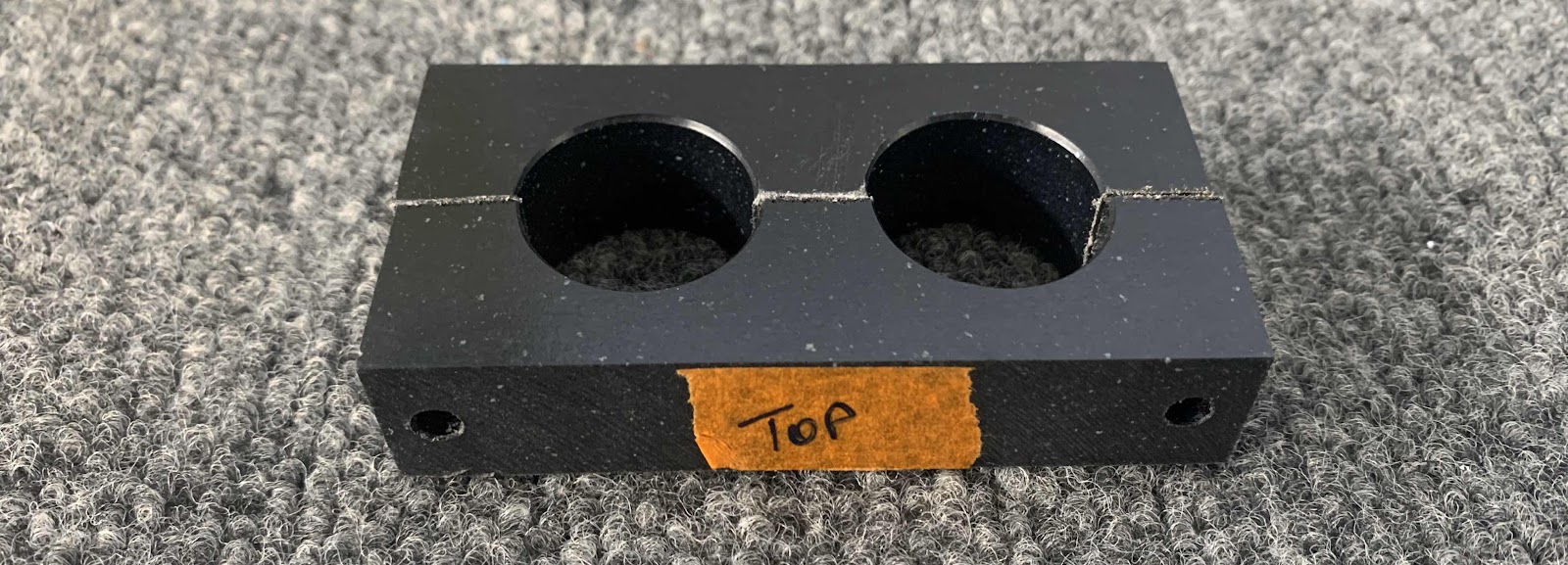
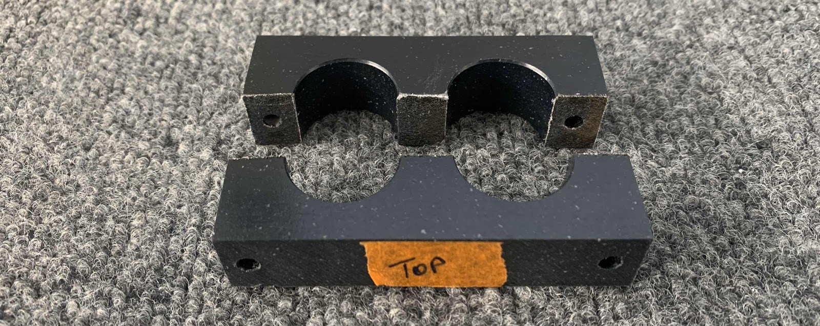
After the holes were final-drilled #10 with the drill press (all the way through), the Block was then cut in half, length wise, with my bandsaw.  Here is the result.


Lastly, I marked each end so the Bearing can be reassembled into it’s original configuration prior to being cut.  I will clean some up the frayed looking edges where the cuts were made prior to installing the assembly on the airplane.

Wednesday, February 5, 2020

Fuselage, Aft Fuselage Attachment (Part 5)

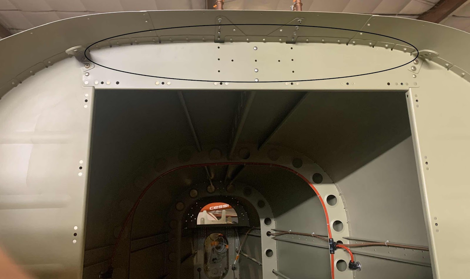
After settling my differences with the two Bulkheads, I moved on to installing the rivets in the F-01406C Bulkhead, F-01474-L & -R Aft Fuselage Top Skins, F-01475 Aft Fuselage Top Skin, F-01475A Skin Doubler and F-14131 Upper Aft Fuselage Rib.  A mixture of AN426AD3-3.5, AN426AD3-4, and AN470AD4-4 were used for the installation.  These rivet locations are identified in the black circle below.

Next, the F-01406A-L Bulkhead was riveted to the F-01474-L Aft Fuselage Top Side Skin (shown below between the arrow heads) using AN426AD3-3.5 rivets (the plans called for 3-3 rivets, but they measured short).....


.....and the F-01406A-R Bulkhead to the F-01474-R Aft Fuselage Top Side Skin.....also using AN425AD3-3.5 rivets.  (Shown below between the arrow heads).

Tuesday, February 4, 2020

Fuselage, Aft Fuselage Attachment (Part 4)

I haven’t talked about it much in the blog up to this point, but I’ve had an ongoing dispute with the F-01406C and F-01406A-L Bulkheads.  Specifically, the area in question, is the area circled in the picture below.  There are four holes in the circled area (counting the one the cleco is installed in).  The hole containing the cleco is dimpled #30 in both bulkheads.  When I initially installed the AN426AD4-4 rivet (with my pneumatic  squeezer)....well, let’s just say, it was absolutely terrible.....the rivet was not completely installed in the hole when it expanded.  This resulted in the holes in each bulkhead to become enlarged and were WAY to large for the required AD4-4 rivet.  Well shit!  What now?

Moving up to #5 rivet wouldn’t be good because it has dimples for a #4 rivet (and I don’t have #5 dimples.....do they even make them?).  I couldn’t just install a screw because the holes are dimpled and would not be flat on the aft side of the hole.  So, I bit the bullet and just ordered two new Bulkheads.  The picture below are the two “new” Bulkheads after being prepared and installed in the Fuselage.

Now, with that dispute settled....on to the next one.  The two Seatbelt Lug Assemblies get riveted to the same two Bulkheads as shown in the plans excerpt below.  The top part of the Lug Assembly bends down and gets in the way when trying to set the top rivet.  I tried several different ideas/way to set the rivets, but couldn’t come up with a suitable install method.  (I’m sure one exists, but I couldn’t figure one out.....maybe an offset rivet set??)


So, to solve the second dispute, I decided to install structural screws in the holes instead of solid rivets.  Each Lug Assembly received two screws and associated hardware.  I used four AN525-8R6 screws, four NAS1149FN832P washers, and four AN365-832A nylok nuts.  Here are the two locations the hardware was installed in the Bulkheads.


Here is a close up of the right side Seatbelt Lug Assembly (and properly installed 470 and 426 rivets in the Bulkheads).....

.....and the left side Seatbelt Lug Assembly (and properly installed 470 and 426 rivets in the Bulkheads).

So, all disputes have been solved with the Bulkhead.....I WIN!

Monday, February 3, 2020

Fuselage, Rudder and Brake System (Part 5)

I let all the pieces for the Brake Pedal Assemblies completely dry for a few days.....now, it’s time to put the Pedals together.  In the picture below, one of the pedals is already assembled along with all the pieces for the remaining three Pedals.

The plans excerpt below shows an exploded view of the five pieces that make up each Pedal and the associated hardware used for the assembly.  

Here are all four of my Pedals completely assembled.  I was able to use my pneumatic squeezer to install all of the solid rivets.  The first picture shows the side your foot goes.....

.....and this is the backside of the pedals.  For the 32 LP4-3 blind rivets, I purchased this pneumatic riveter from Harbor Freight.  It was relatively inexpensive and had good customer reviews.  So far, it has worked very well.  (There are MANY blind rivets that will be installed in the Baggage Area, so it will be used for those rivets also).

I ordered some generic wing walk from Van’s and will install it on the foot side of the pedal in a future session.