
Tonight, I started working on the Bearing Blocks. There are two F-1039A Rudder Pedal Bearing Blocks and they get prepared the same way. To start, the aluminum Bearing Block template is clamped to one of the Bearing Blocks and the two guide holes are match-drilled #12 in the Bearing Block about 3mm deep. In the picture below, the Bearing Block on the right has the template clamped into position and the left one shows the template removed with the two match-drilled #12 holes drilled in the Block. Lastly, those two holes were final-drilled #10 all the way through the Bearing Block using the drill press.
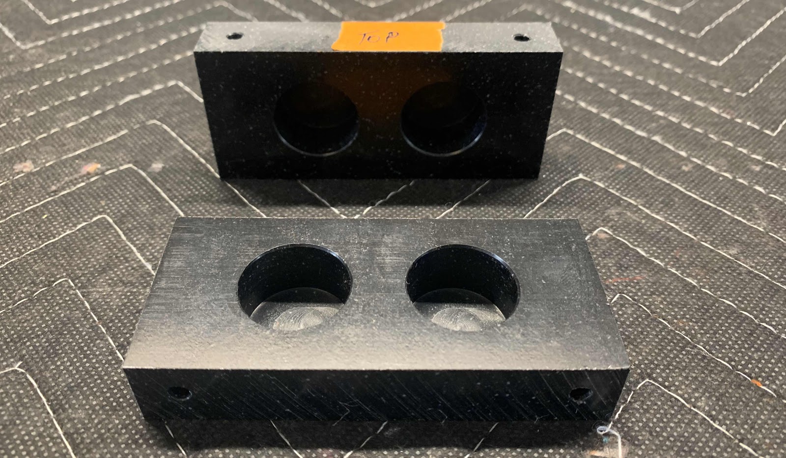
Here are the two completed F-1039A Bearing Blocks.
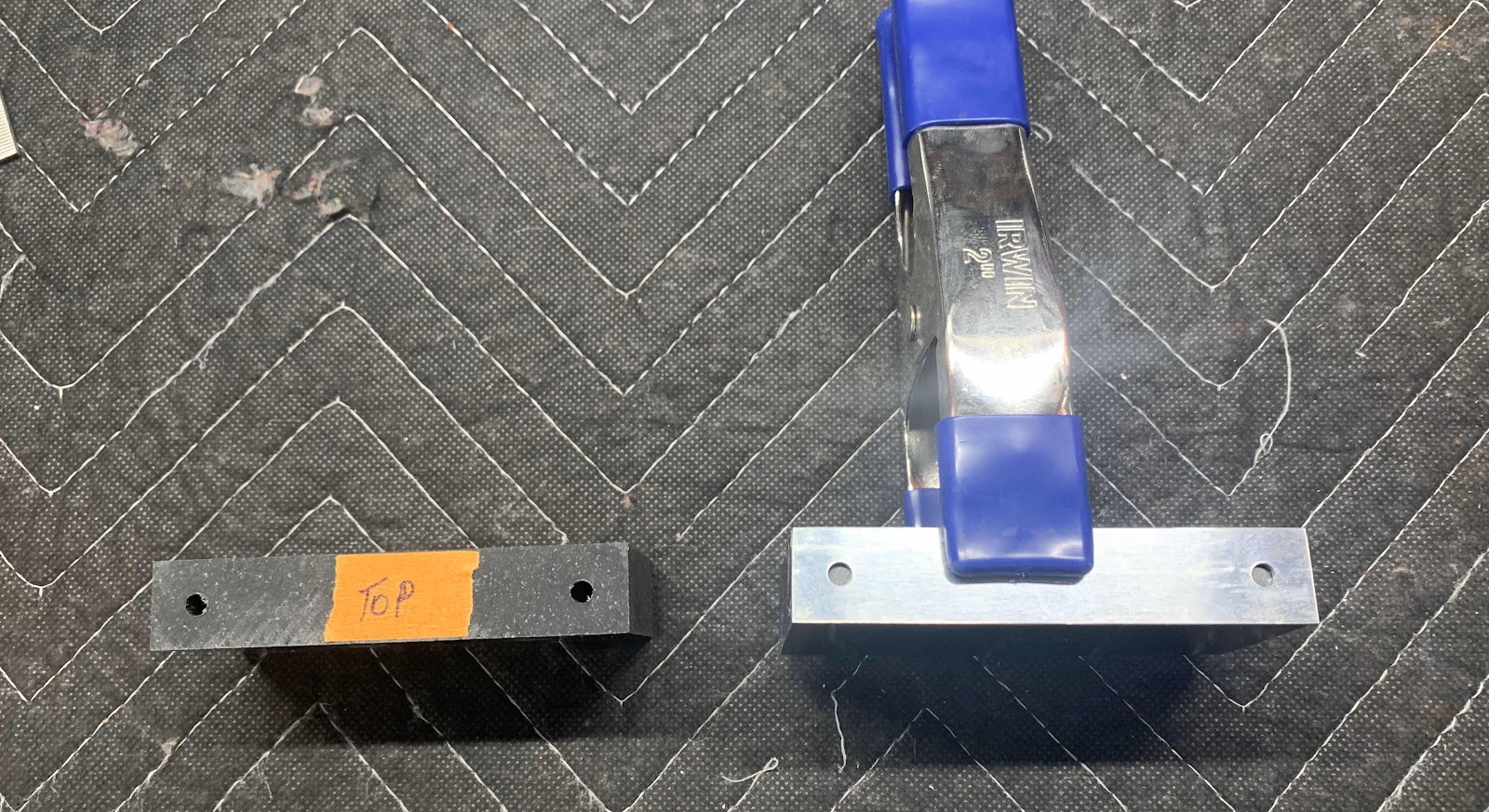
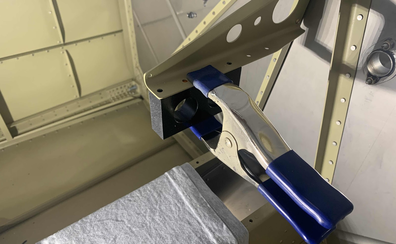
The F-6115 Rudder Pedal Bearing Block was prepared in a similar fashion. However, instead of using a template as a drill guide, this Block was clamped to the F-14104 Support Angle and the pre-drilled holes in the Angle were used as drill guides. The forward and aft holes were initially match-drilled to #12 and final-drilled to #10 with the drill press.
After the holes were final-drilled #10 with the drill press (all the way through), the Block was then cut in half, length wise, with my bandsaw. Here is the result.
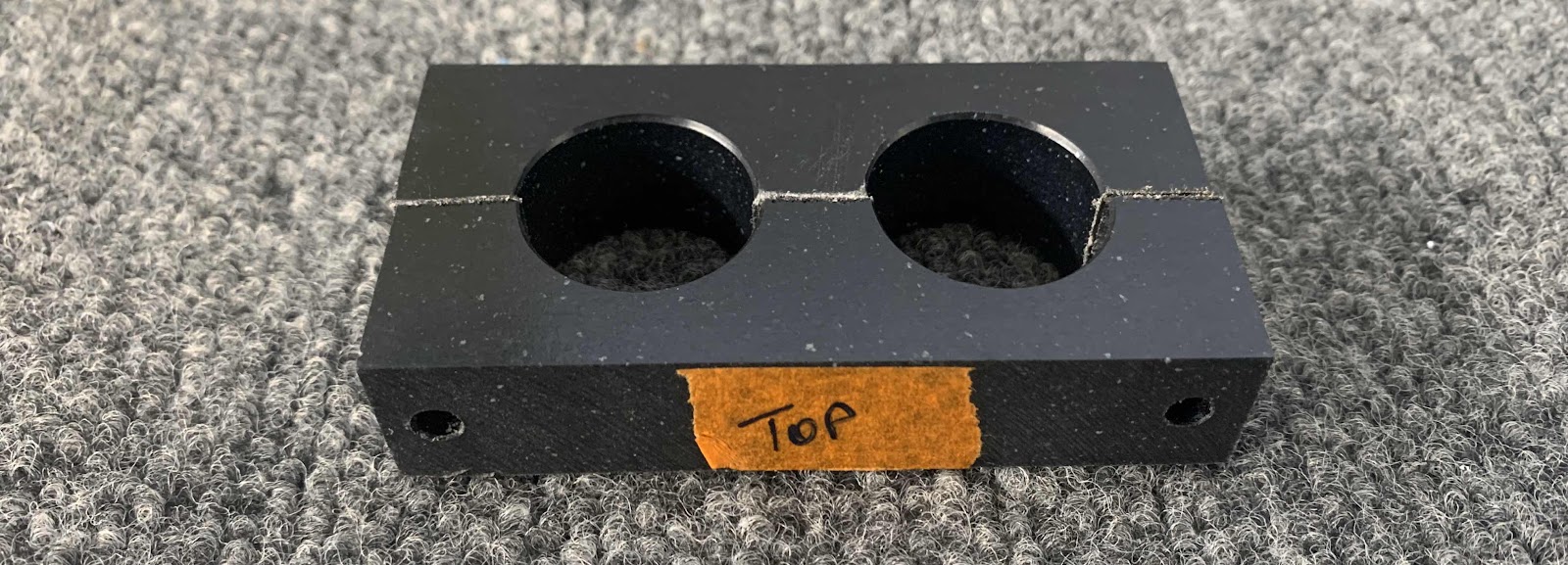
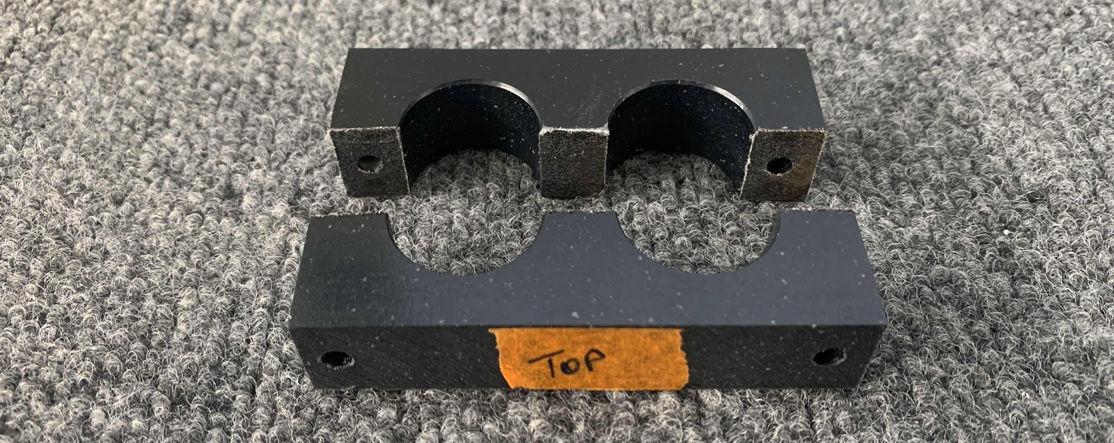
Lastly, I marked each end so the Bearing can be reassembled into it’s original configuration prior to being cut. I will clean some up the frayed looking edges where the cuts were made prior to installing the assembly on the airplane.