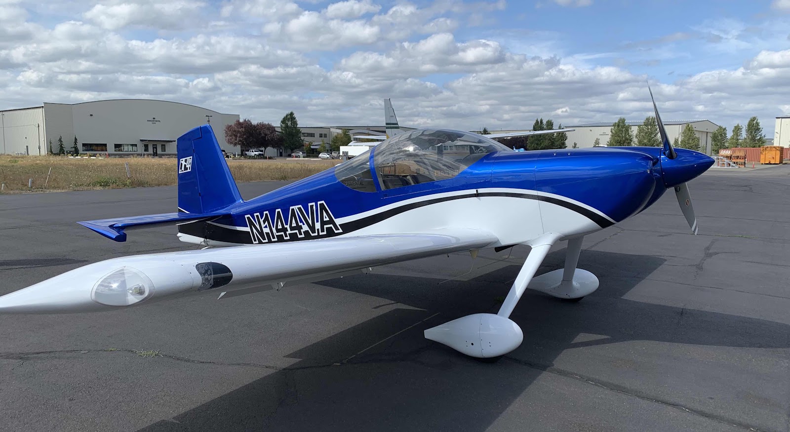
This blog was created to memorialize the building process of my Van's Aircraft RV-14 and to satisfy the requirements for certification in the Experimental Amateur Built Aircraft category. It will also serve as a central location for ME to reference in the future on processes and techniques I used during the build. Additionally, it will allow my family, friends, and other interested builders the opportunity to follow along during my build…..and might be helpful to someone along the way.
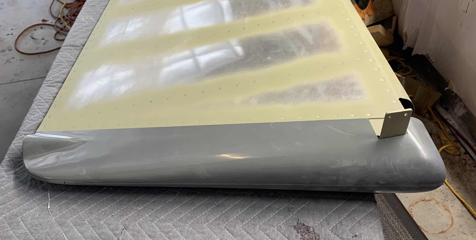
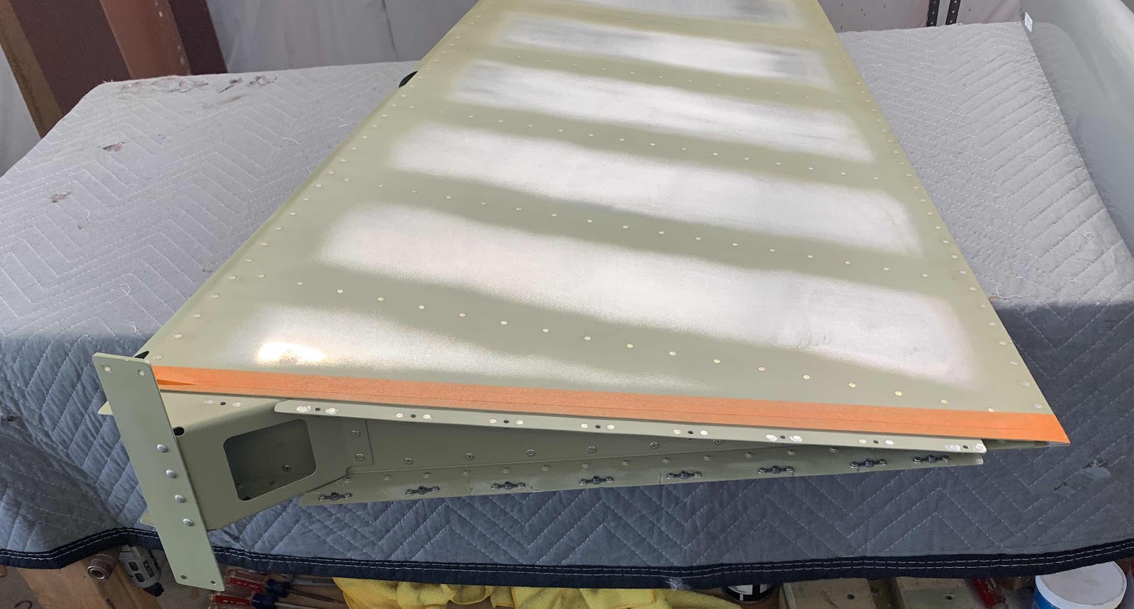
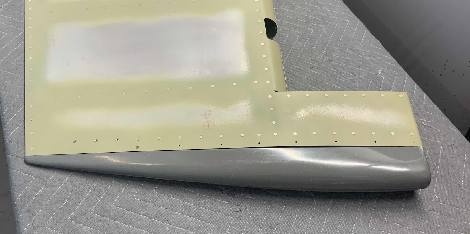
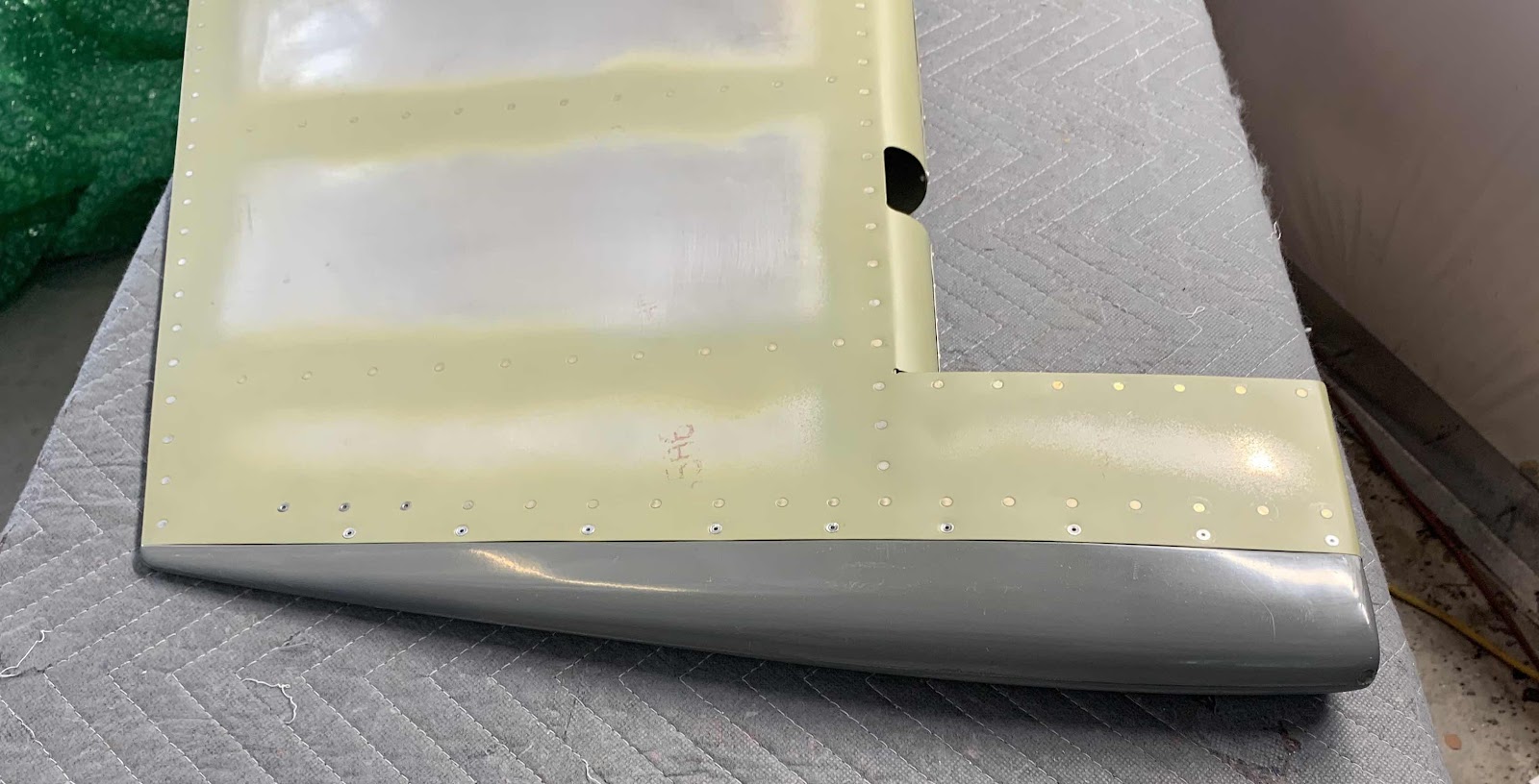
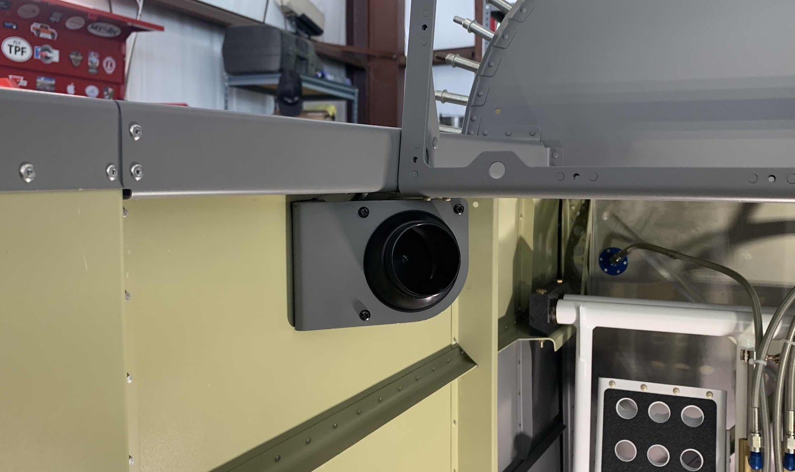
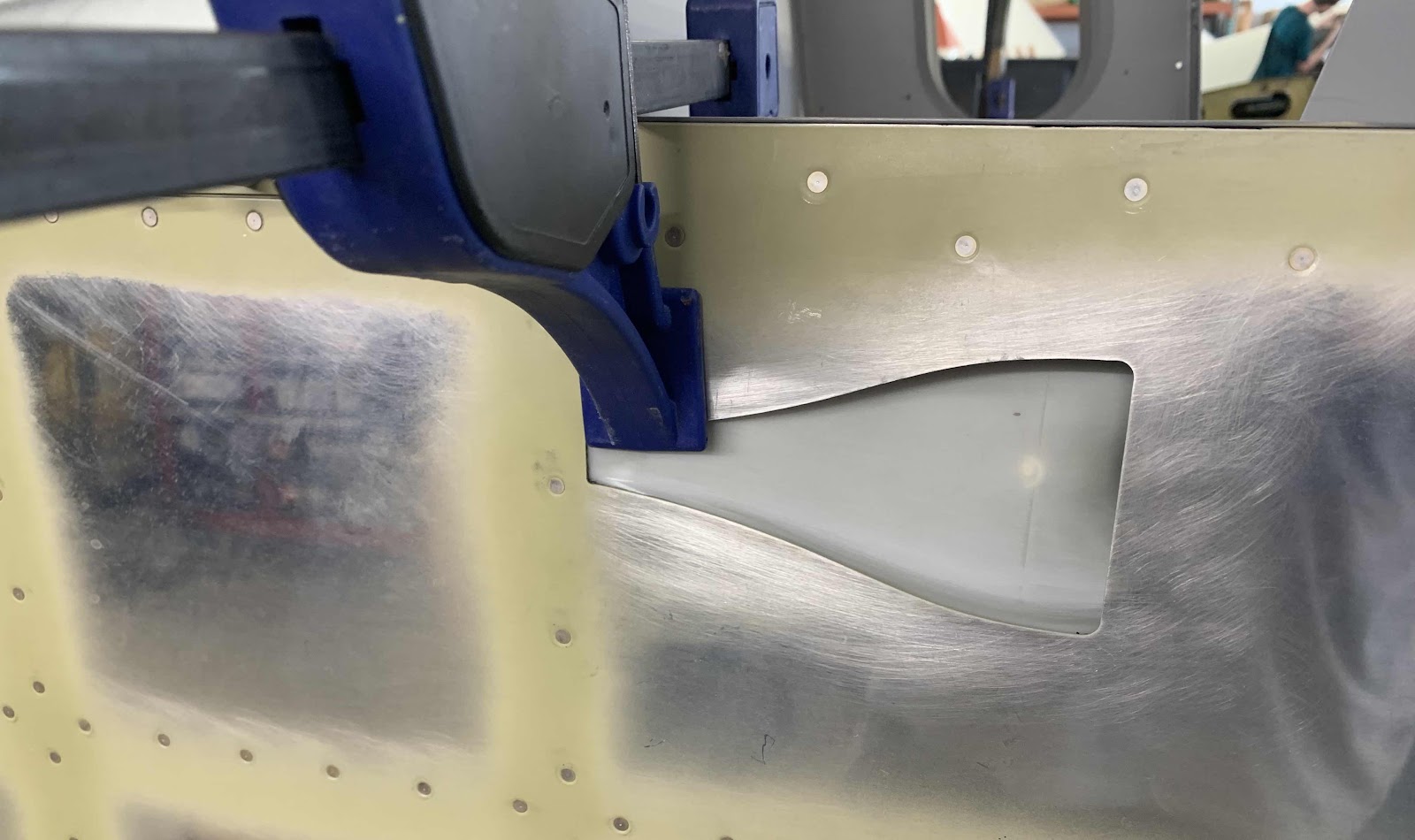
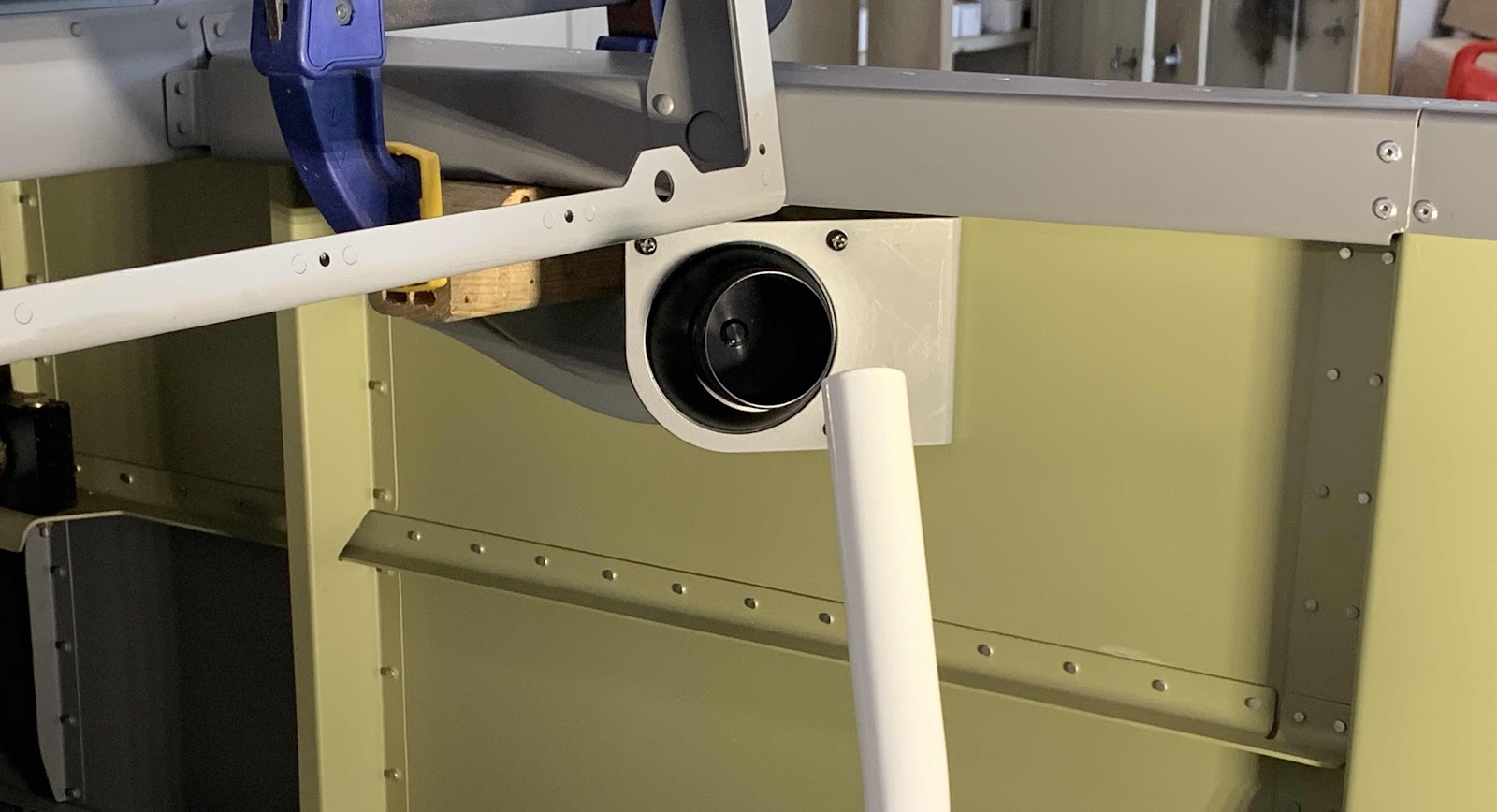
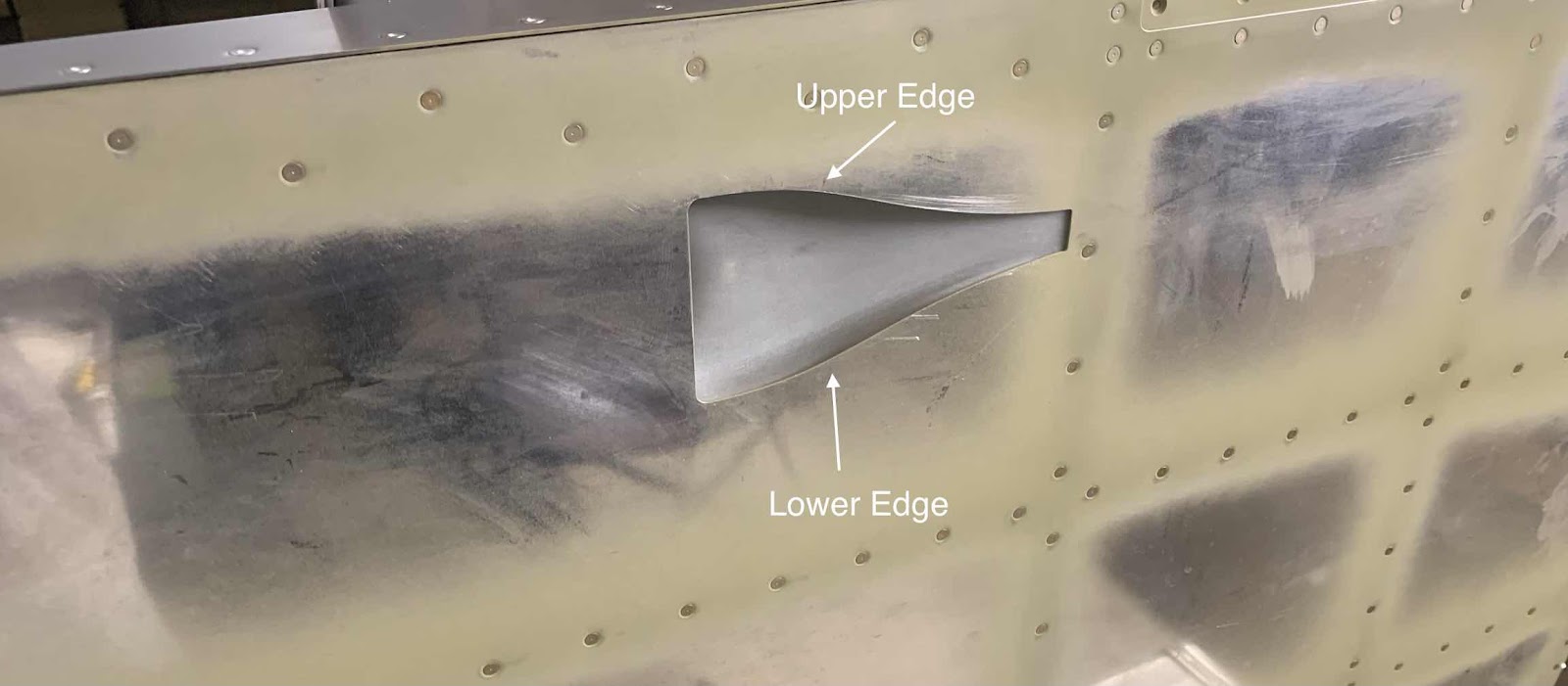
Continuing the preparation of the R-911 Rudder Bottom Fairing. All of the fitting of the Fairing to the bottom of that Rudder has been more or less completed. Here are a couple of photos showing the final fitting on the right side of the Rudder.
Here is an overall view.....
.....the forward end fitted around the R-405PD Rudder Horn.....
.....and the aft portion aligned with the Rudder’s trailing edge.
Wing all the major fitting completed, it’s now time to match-drill #40 the holes in the Faring and R-00918 Attach Straps. The plans provide the measurements to locate the holes on the Fairing. In the pictures below, the left and right sides of the Fairing have been marked based on these measurements. The only difference between the two sides is the last hole on the aft side on one of the Fairings. That hole is offset to allow clearance for the nutplates and attaching hardware. The right side of the Fairing (second picture) is the side I chose to offset.
After the initial-match drilling #40, the same holes were final-drilled #27. Here is the completed right side.....
.....and the completed left side.
Now, the 16 K1000-06 nutplates will get installed on the Attach Straps. This is accomplished by using a #6 screw and a K1000-06 nutplate as a drill guide to final-drill #40 the nutplate attach holes for each of the #27 holes final-drilled in the Attach Straps. The next steps are:
1. Countersink the nutplate attach holes in the Horn Brace (x2, one on the right side and one on the left side)
2. Dimple the nutplate attach holes in the Attach Straps for flush mount rivets (16 locations, eight on each side)
3. Dimple the the nutplate rivet attach holes in 16 (of the 18) for the dimples in the Attach Straps
4. Rivet the 18 nutplates in the Rudder Assembly
These two pictures show all that work completed on the right side.....
This post is WAY late, but on May 21, 2020, we ordered the Finishing Kit. If memory serves, the lead time when we ordered the kit was 20 weeks. The crate date for our Kit is August 24, 2020 (and was confirmed). Kim from Van’s advised the crating department is WAY behind (3-4 weeks) due to Covid-19 and more people wanting kits due to being quarantined. I anticipate the kit will arrive the third or fourth week of September.....getting close!
So, now time to sit back and wait for the Finishing Kit to arrive.....AND.....complete the Fuselage Kit prior to its arrival. Here are a couple of pictures we took during the Van’s factory tour for motivation!!!!!
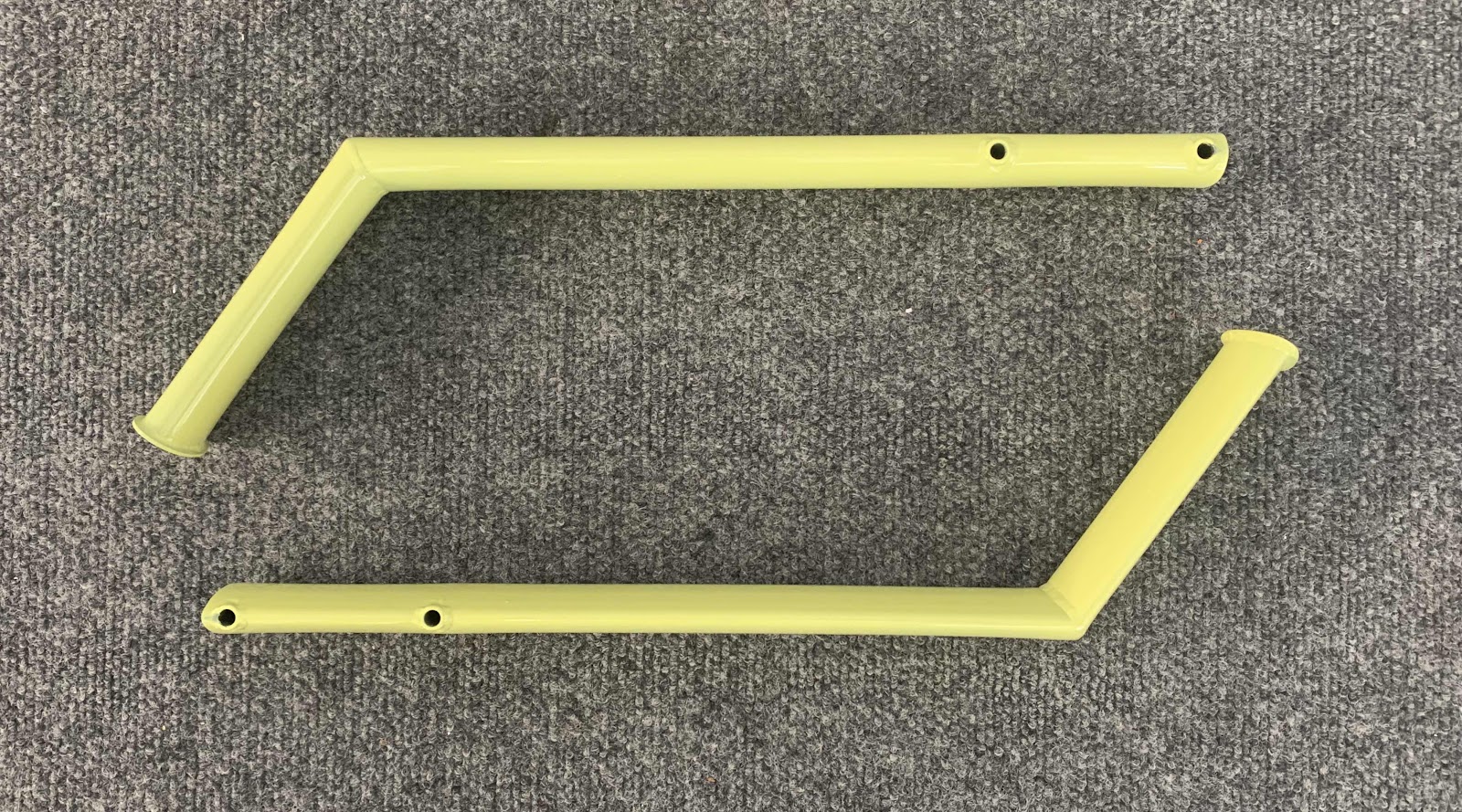
In order to keep forward momentum while waiting for the Finishing Kit, I ordered the F-00018-L & -R Steps from Van’s. I originally thought I would not need the Steps because I’m building a taildragger. However, I saw an RV-14 at Sun-N-Fun in 2019 and realized the steps were definitely necessary.
Additionally, when we visited the Van’s factory in September 2019, it was evident the step was needed when I got my RV-14 ride.
Initially, I was going to wait a little to complete the steps because I’m not 100% sure they won’t be in the way during the Wing installation. However, Mother Nature forced my hand. After a month or so, I noticed a tiny little bit of corrosion starting to form on the Steps. I removed the corrosion and primed the steps. Take that corrosion! Here are a couple pictures of the primed Steps.
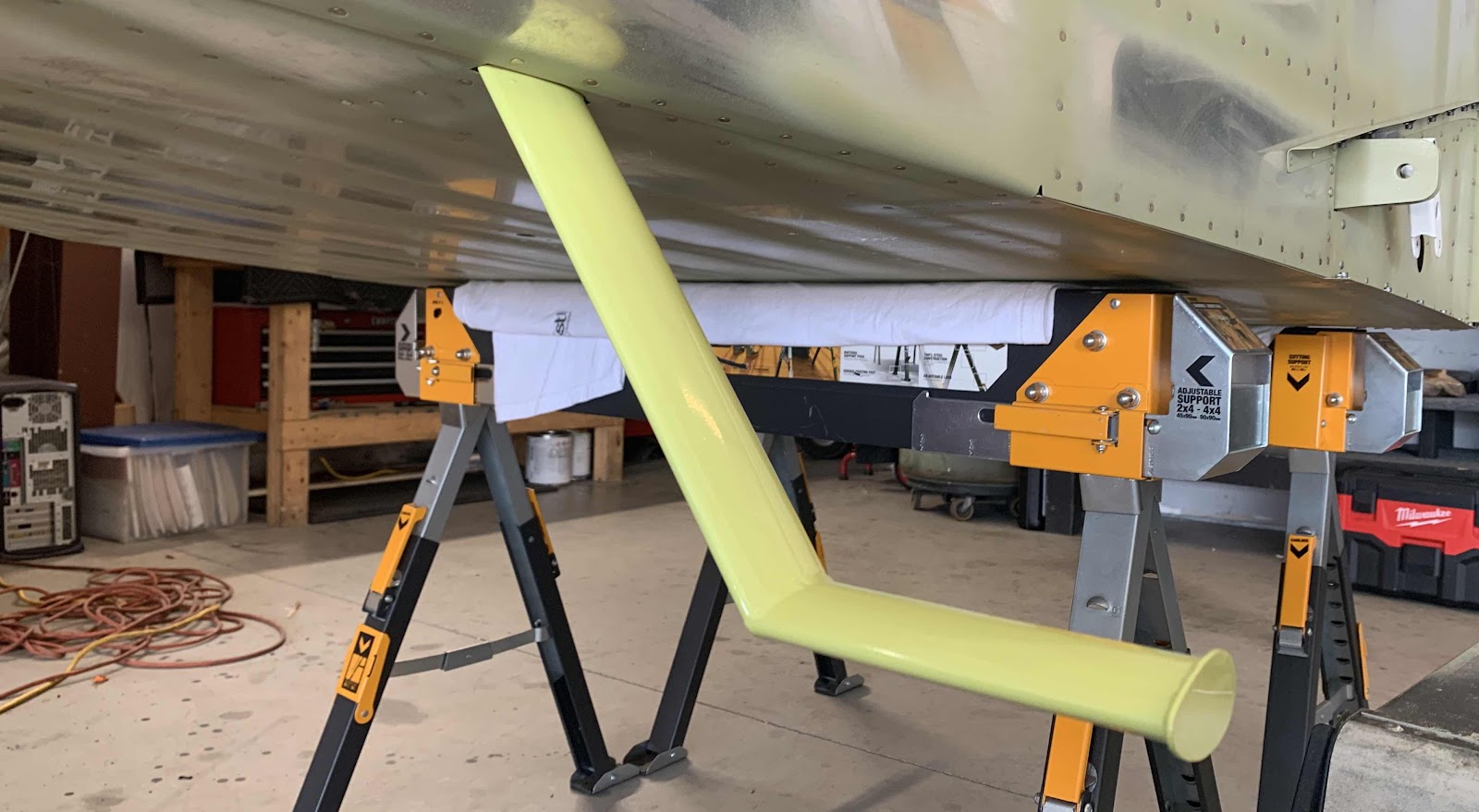
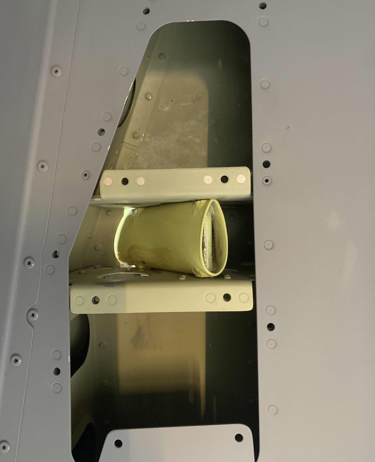
Now that the Steps are primed, I can’t just let them sit around and wait. So, I decided to install them on the airplane. Here’s the Step for the right side.....
.....and the left side.
Done. The Steps are happily installed on the airplane and ready for work.
While waiting for the Finishing Kit, I decided to return to Section 12 and work on the Fairings. I haven’t done much fiberglass work in the past, so I decided to start with the Rudder (top fairing) since it looks like the easiest (also the first steps in the Section.....so there’s that).
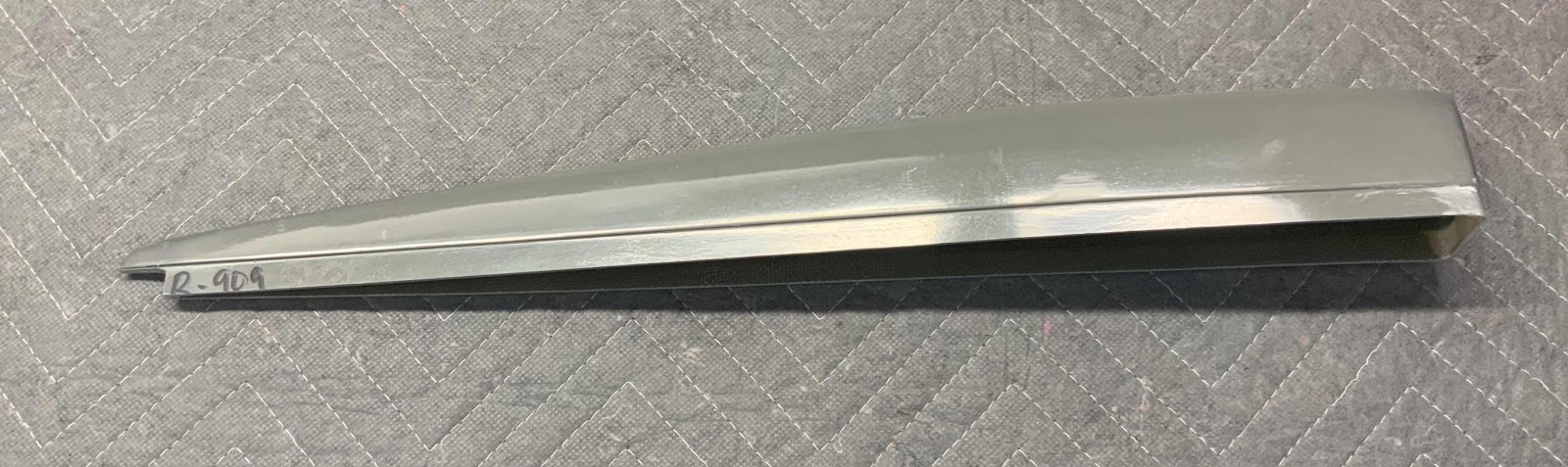
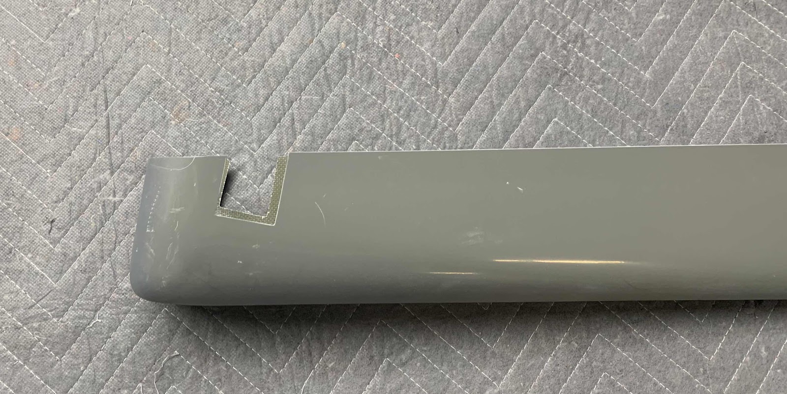
Pictured below is the R-909 Rudder Top Fairing. The first step was to removed a “notch” on the left side of the Fairing to remove any interference between the flange and the Rudder Assembly trailing edge. I kind of eyeballed it to start and then removed a little more material until it fit correctly. I actually inserted the Fairing onto the Rudder a few times to see where material had to be removed.
Here is a little closer look at the “notch”. It fit perfectly on top of the Rudder.
The next area that needed some trimming was the front of the Fairing. In the area circled below, the flat face on the front of the fairing continued all the way down toward the bottom. If you look on the side of the fairing, there is a “lip” that was created during manufacturing.....this allows the Fairing to line up with the Skin of the Rudder smoothly (more on that later). This “lip” also had to be created on the front face of the Fairing to ensure a proper fit. I used 60 grit sand paper on a popsicle stick to make the “lip”.
This is the Fairing inserted into the top of the Rudder once all the trimming was completed.
The plans state to make sure the aft end of the Fairing aligned with the trailing edge of the Rudder....shown below.
Here is the forward end of the Fairing inserted into the Rudder.
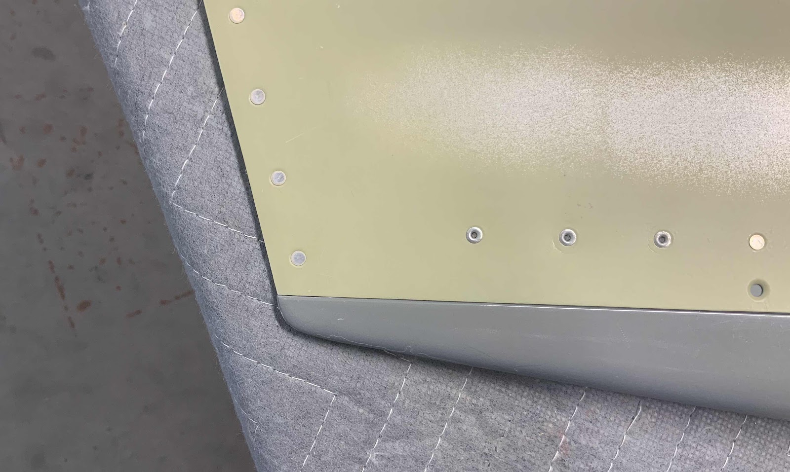
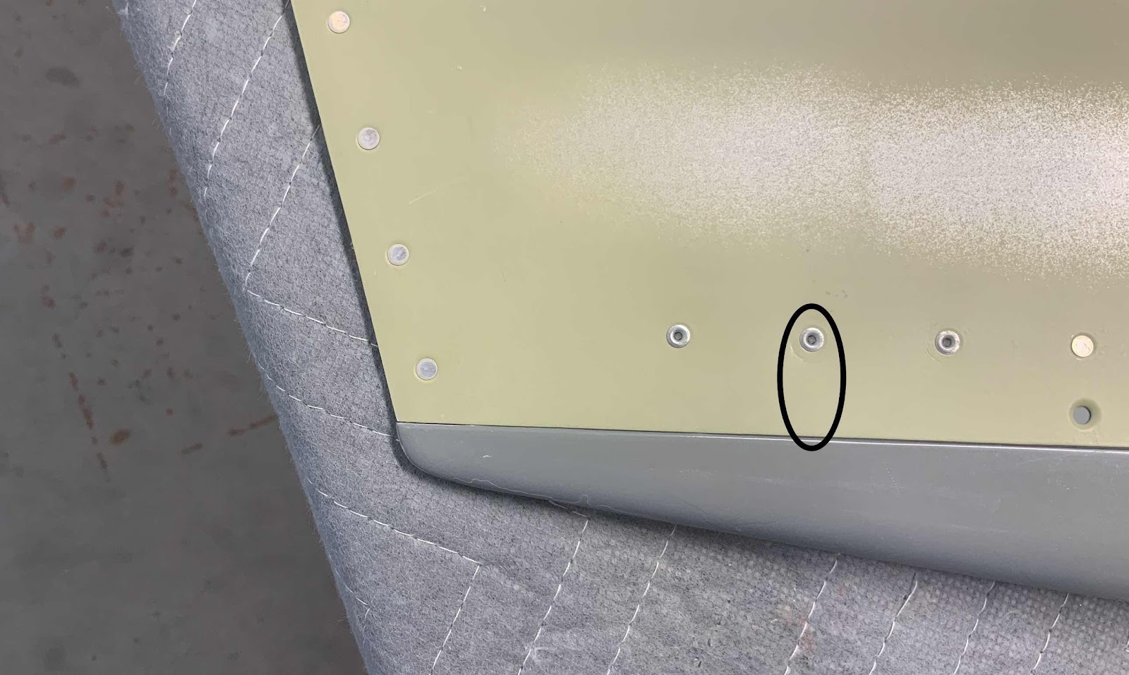
Now, here is an issue. In the plans except below, the picture shows that 18 CS4-4 rivets (nine on each side) will be used to install the fairing onto the Rudder. Problem is.....there were only eight holes prepunched in each side of the Rudder Skin for a total of 16 holes. So, what do I do? Because the Top Rudder Fairing tapers toward the aft side, there is very little room to dimple the hole or install “opposing” rivets on each side of the Rudder Skin. I suspect that is why (two pictures above, right edge of the picture ) that the plans had you final drill and dimple the one single hole on either side of the Rudder Skin.
Here is the same picture as shown above. According to the plans excerpt above, the last rivet used to install the Fairing on the Rudder is located just above the second to last hole (circled below). However, as I was saying earlier, there is not a prepunched hole here. So, where is the disconnects between the plans and the prepunch?? It is roughly six inches from the last prepunched hole to the end the Fairing. Even though there are eight other rivets to hold the Fairing in place, I felt like that was a large enough gap to install another rivet. So, as I mentioned there is little room left inside the Fairing for “opposing rivets”. Here is what I did:
1. Measured the distance between the prepunched holes (2 inches)
2. For one side, I measured 2 inches from the forward side of the prepunched and dimpled hole
3. For the other side, I measured 2 inches from the aft side of the prepunched and dimpled hole
4. Measured the distance from the top of the Rudder Skin to the center of the prepunched hole
This “method” kept the holes in line with the existing holes and offset the holes enough to allow a drill bit (#40 then #30) and rivets to be installed. Again, because the area is so tight and you can’t get a dimple die and squeezer in there. I used a Close Quarters Dimple Die from Cleaveland Aircraft Tools to dimple the hole.
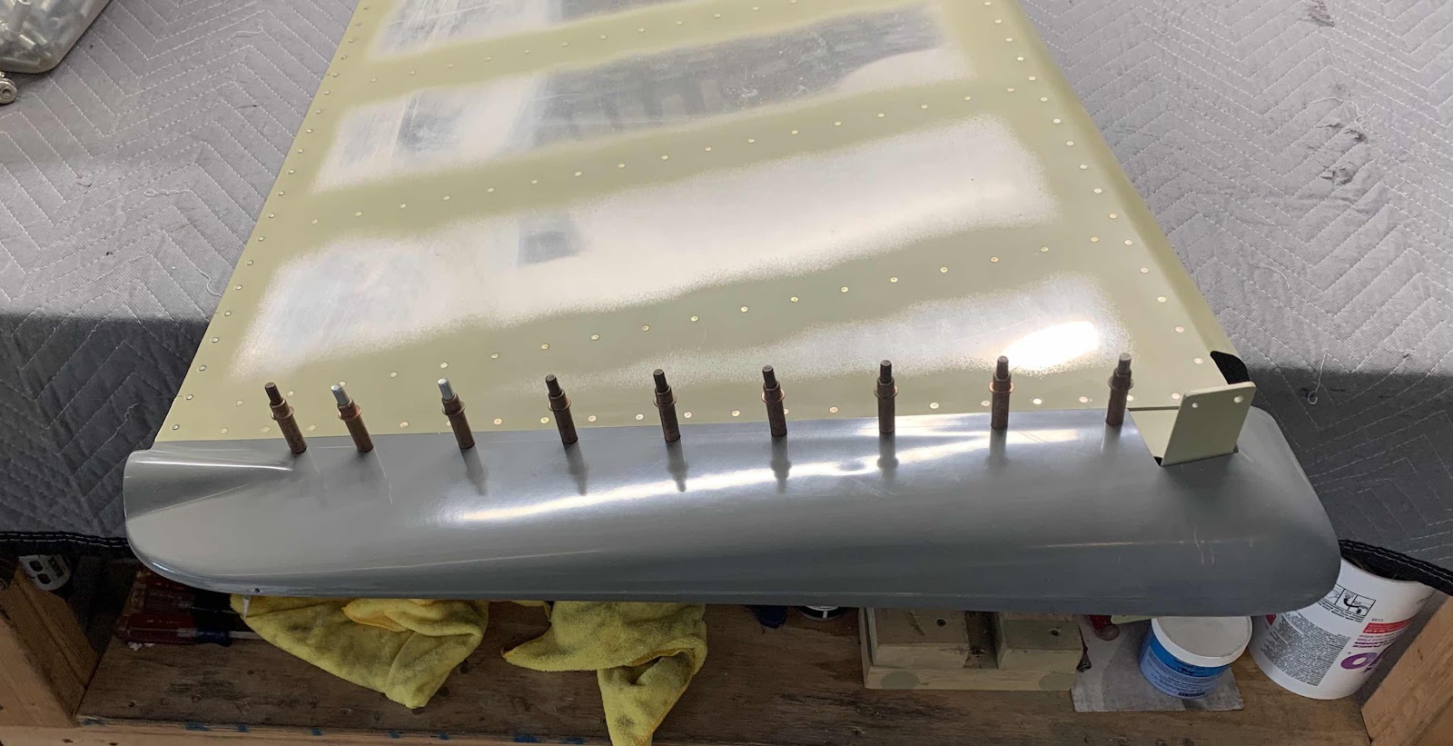
Now that “issue” is solved.....let’s move on to the other eight holes. The picture below shows the prepared Top Fairing (including the addition of the “extra” hole discussed above.....making a total of nine like the plans). To get to this point, each of the holes were initially drilled to #40 and then #30 (which is why you see the copper clecos). Lastly, they were dimpled using 120° Dimple Dies for the CS4-4 pop rivets. Here is the left side.....
.....and the right side.
To complete the installation, the 18 CS4-4 pop rivets (nine on each side) were installed. Here is the right side.....
.....and the left side. The final step is to do some sanding and make it all look pretty.
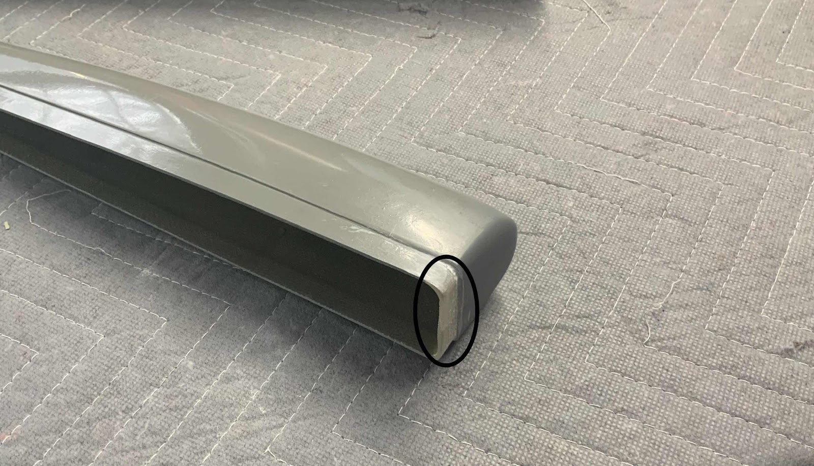
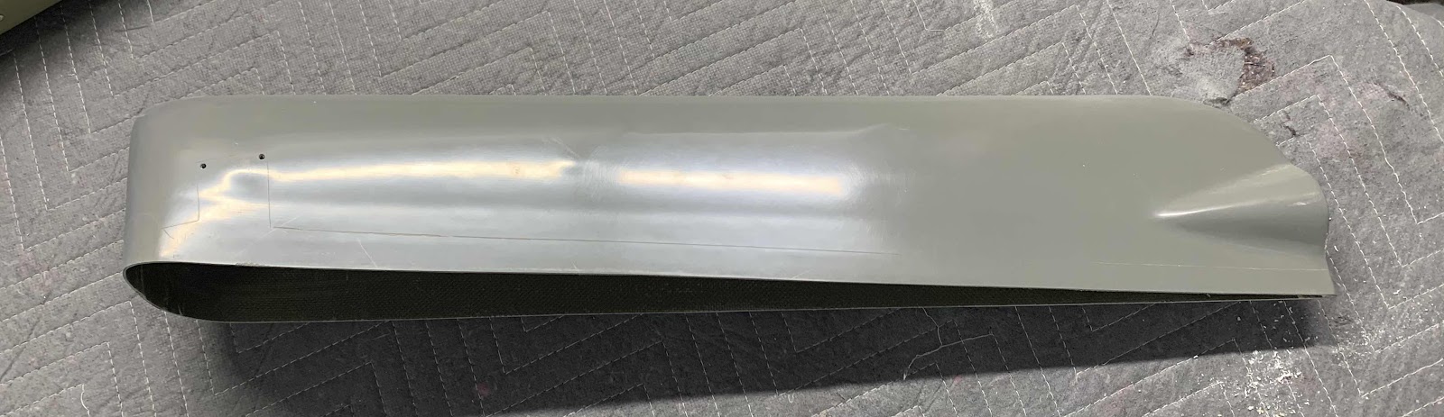
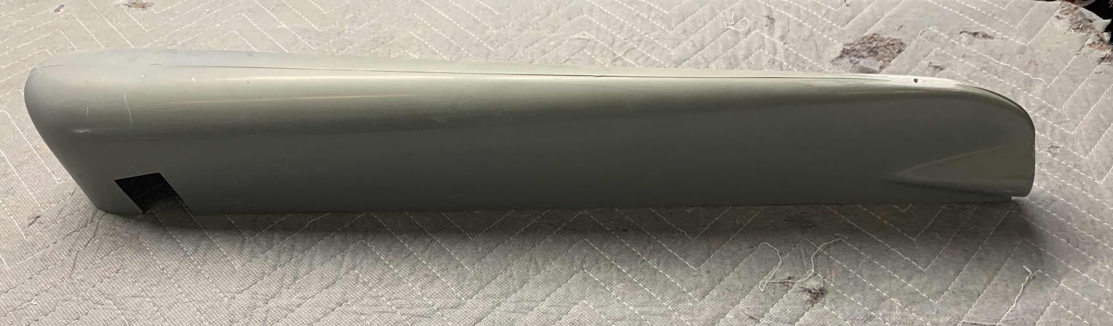
After completing the Rudder Top Fairing, I moved on to the R-911 Rudder Bottom Fairing. If you look closely, you can see a fine line outlining the material that will need to be removed.
Looks like this on the plans.....
I completed most of the material removal, but will complete the final fitting during the next session. Here are a few pictures.....
Next, the FWD and AFT Roll Bar Assemblies were clecoed to the F-01231D Roll Bar Bases to be match-drilled. There are lots of holes to match-drill in this location also. Because of all the clecos holding the assembly together, you will have to use a 6” or 12” drill bit. The plans suggest using a 12” bit, but I used a 6” inch bit and it worked out just fine…..gives you a little more control when you’re drilling (either will work - just your preference). This picture shows the outside of the right (copilot) side…..
…..and the inside of the right (copilot) side.
This is the outside of the left (pilot) side…..
…..and the inside left (pilot) side.
The next two pictures show the F-01432A Roll Bar Brace Assembly clecoed to the F-01475 Top Skin and the F-01406C Bulkhead. (The left and right brackets were previously riveted to the Roll Bar Brace Assembly).
Here is the other end of the Assembly clecoed to the FWD and AFT Roll Bar Assemblies. (Additionally, here are a few of the 426 rivets used on the FWD Roll Bar Assembly and the CS4-4 rivets used on the Window Shims and AFT Roll Bar Assembly).