
While waiting for the Finishing Kit, I decided to return to Section 12 and work on the Fairings. I haven’t done much fiberglass work in the past, so I decided to start with the Rudder (top fairing) since it looks like the easiest (also the first steps in the Section.....so there’s that).
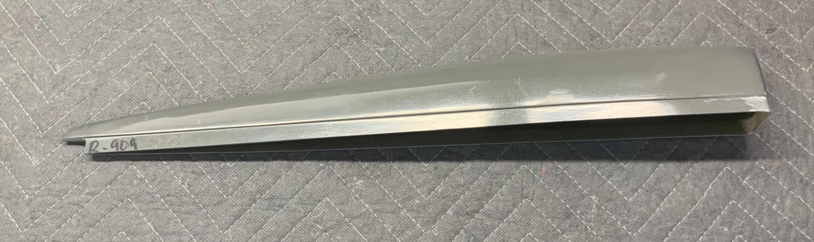
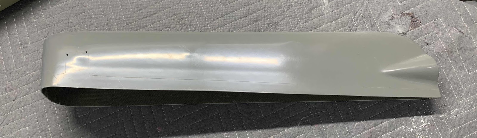
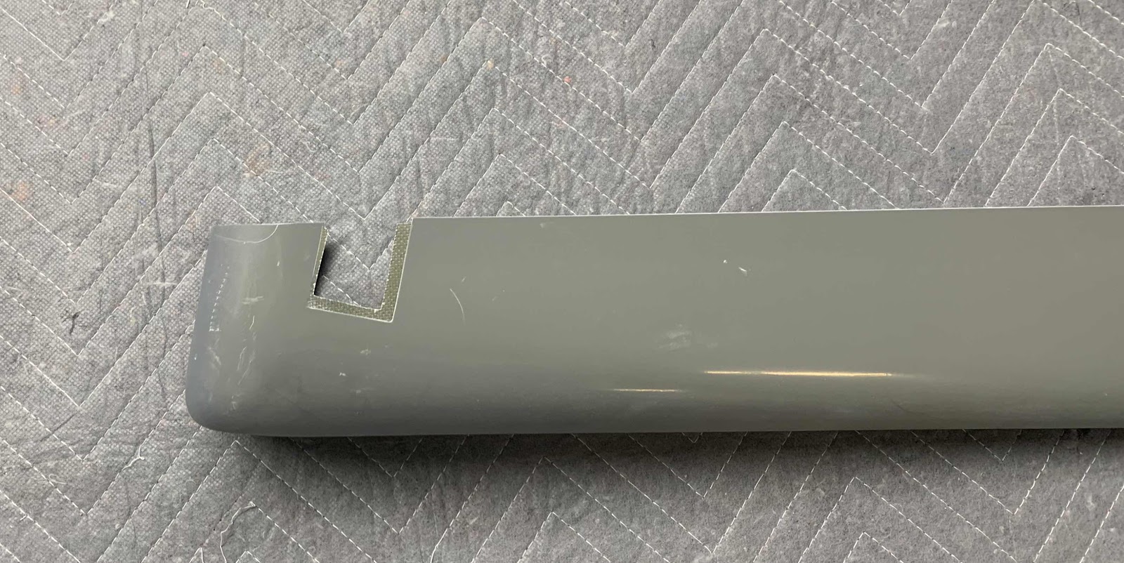
Pictured below is the R-909 Rudder Top Fairing. The first step was to removed a “notch” on the left side of the Fairing to remove any interference between the flange and the Rudder Assembly trailing edge. I kind of eyeballed it to start and then removed a little more material until it fit correctly. I actually inserted the Fairing onto the Rudder a few times to see where material had to be removed.
Here is a little closer look at the “notch”. It fit perfectly on top of the Rudder.

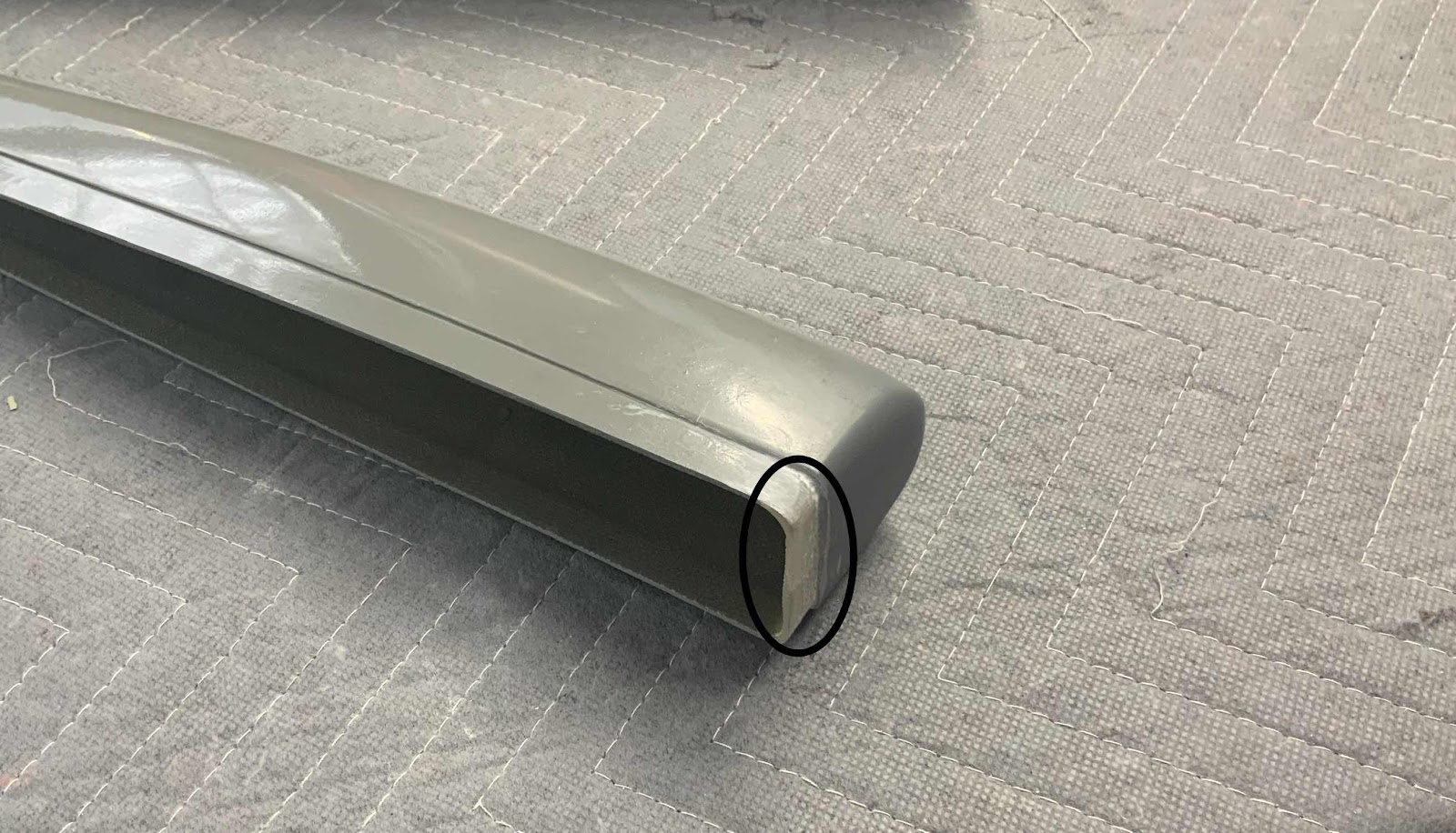
The next area that needed some trimming was the front of the Fairing. In the area circled below, the flat face on the front of the fairing continued all the way down toward the bottom. If you look on the side of the fairing, there is a “lip” that was created during manufacturing.....this allows the Fairing to line up with the Skin of the Rudder smoothly (more on that later). This “lip” also had to be created on the front face of the Fairing to ensure a proper fit. I used 60 grit sand paper on a popsicle stick to make the “lip”.
This is the Fairing inserted into the top of the Rudder once all the trimming was completed.
The plans state to make sure the aft end of the Fairing aligned with the trailing edge of the Rudder....shown below.
Here is the forward end of the Fairing inserted into the Rudder.

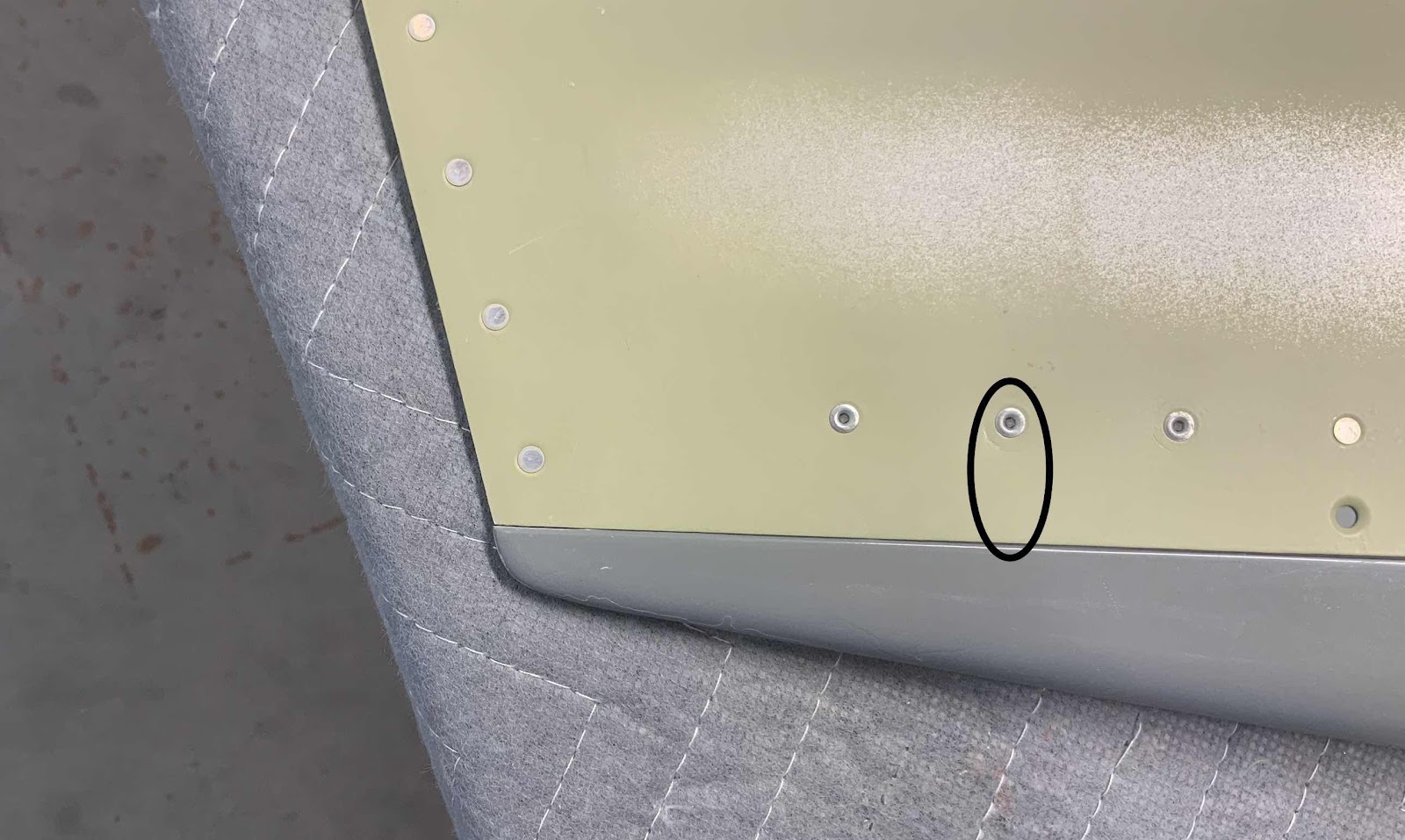
Now, here is an issue. In the plans except below, the picture shows that 18 CS4-4 rivets (nine on each side) will be used to install the fairing onto the Rudder. Problem is.....there were only eight holes prepunched in each side of the Rudder Skin for a total of 16 holes. So, what do I do? Because the Top Rudder Fairing tapers toward the aft side, there is very little room to dimple the hole or install “opposing” rivets on each side of the Rudder Skin. I suspect that is why (two pictures above, right edge of the picture ) that the plans had you final drill and dimple the one single hole on either side of the Rudder Skin.

Here is the same picture as shown above. According to the plans excerpt above, the last rivet used to install the Fairing on the Rudder is located just above the second to last hole (circled below). However, as I was saying earlier, there is not a prepunched hole here. So, where is the disconnects between the plans and the prepunch?? It is roughly six inches from the last prepunched hole to the end the Fairing. Even though there are eight other rivets to hold the Fairing in place, I felt like that was a large enough gap to install another rivet. So, as I mentioned there is little room left inside the Fairing for “opposing rivets”. Here is what I did:
1. Measured the distance between the prepunched holes (2 inches)
2. For one side, I measured 2 inches from the forward side of the prepunched and dimpled hole
3. For the other side, I measured 2 inches from the aft side of the prepunched and dimpled hole
4. Measured the distance from the top of the Rudder Skin to the center of the prepunched hole
This “method” kept the holes in line with the existing holes and offset the holes enough to allow a drill bit (#40 then #30) and rivets to be installed. Again, because the area is so tight and you can’t get a dimple die and squeezer in there. I used a Close Quarters Dimple Die from Cleaveland Aircraft Tools to dimple the hole.
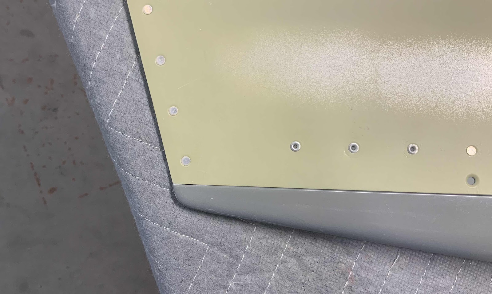
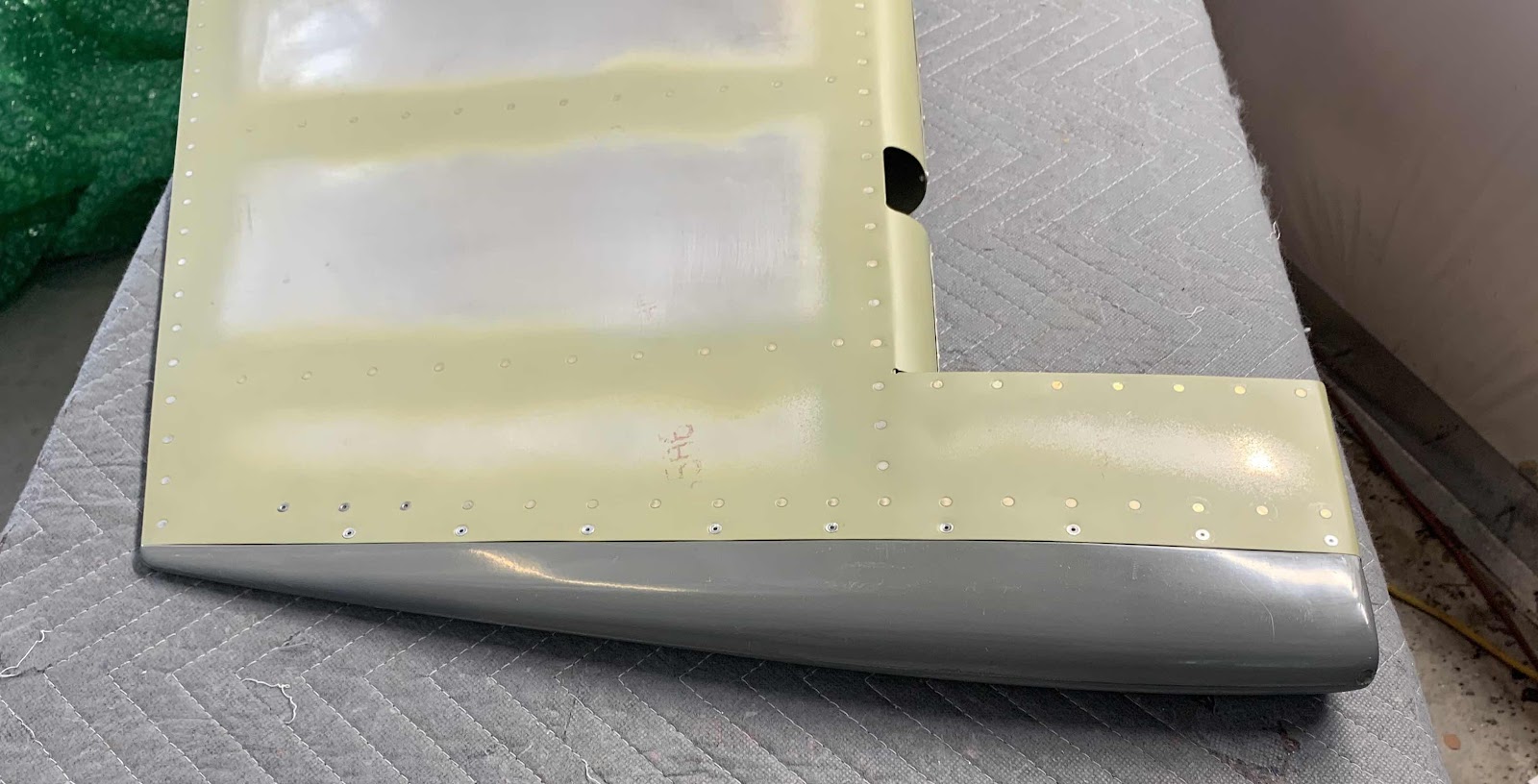
Now that “issue” is solved.....let’s move on to the other eight holes. The picture below shows the prepared Top Fairing (including the addition of the “extra” hole discussed above.....making a total of nine like the plans). To get to this point, each of the holes were initially drilled to #40 and then #30 (which is why you see the copper clecos). Lastly, they were dimpled using 120° Dimple Dies for the CS4-4 pop rivets. Here is the left side.....

.....and the right side.

To complete the installation, the 18 CS4-4 pop rivets (nine on each side) were installed. Here is the right side.....

.....and the left side. The final step is to do some sanding and make it all look pretty.
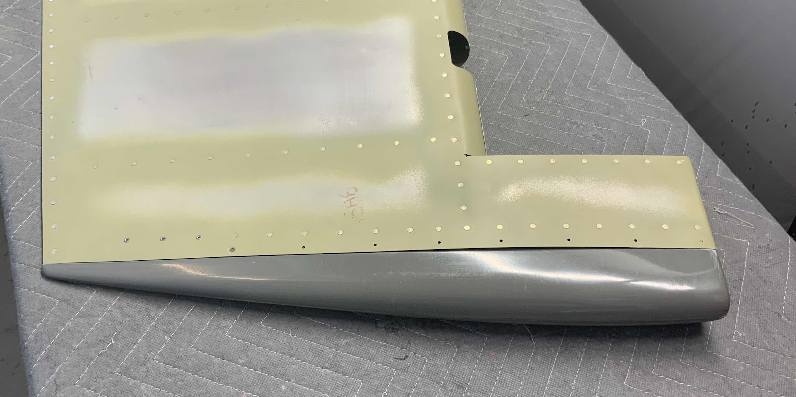
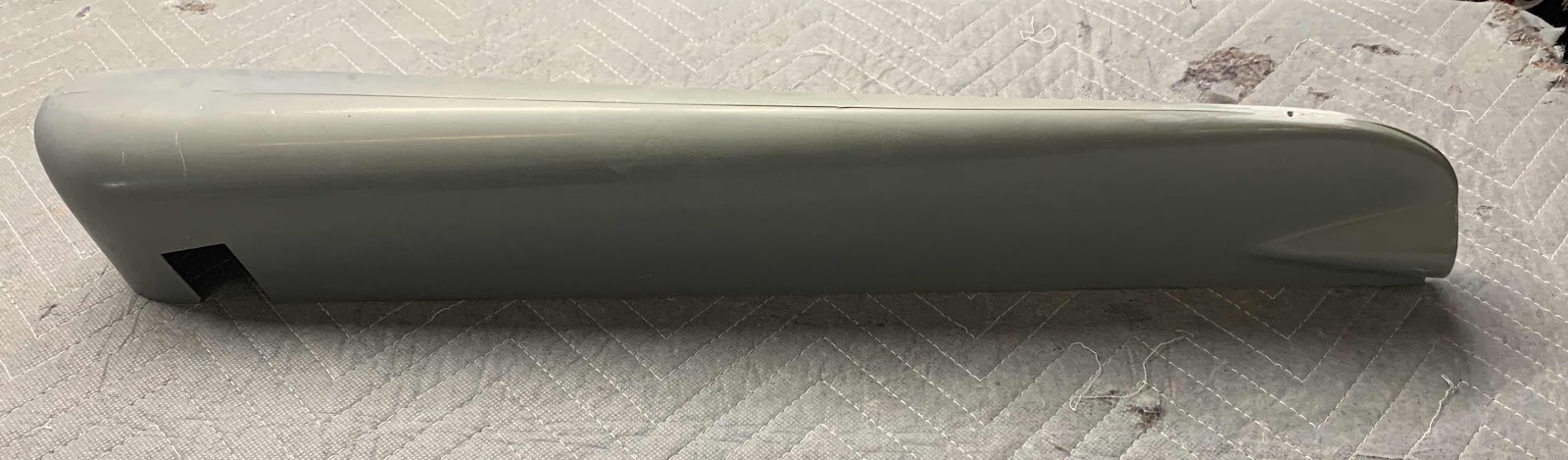
After completing the Rudder Top Fairing, I moved on to the R-911 Rudder Bottom Fairing. If you look closely, you can see a fine line outlining the material that will need to be removed.
Looks like this on the plans.....

I completed most of the material removal, but will complete the final fitting during the next session. Here are a few pictures.....

I will pick it up here tomorrow........