The following work was completed on Friday, February 3, 2023.
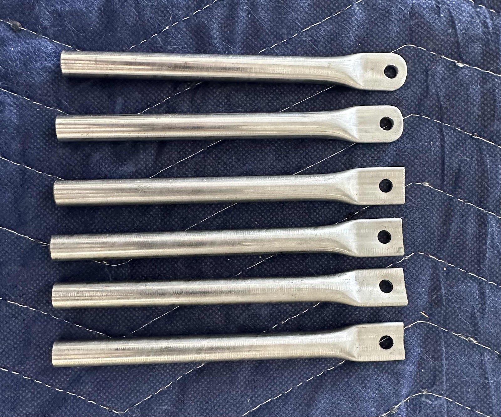
I started this work session by making the Forward Exhaust Hanger Brackets. The first step was to modify two of the Exhaust Support Tubes. Each tube had to be be cut to a length of 3 1/4 inches, have the corners of the bolt end rounded and the opposite end flared. This picture only shows the rounded bolt ends of the two tubes. Next, I used a band saw to cut the tubes to the appropriate length and flared the opposite end. (More on that below).
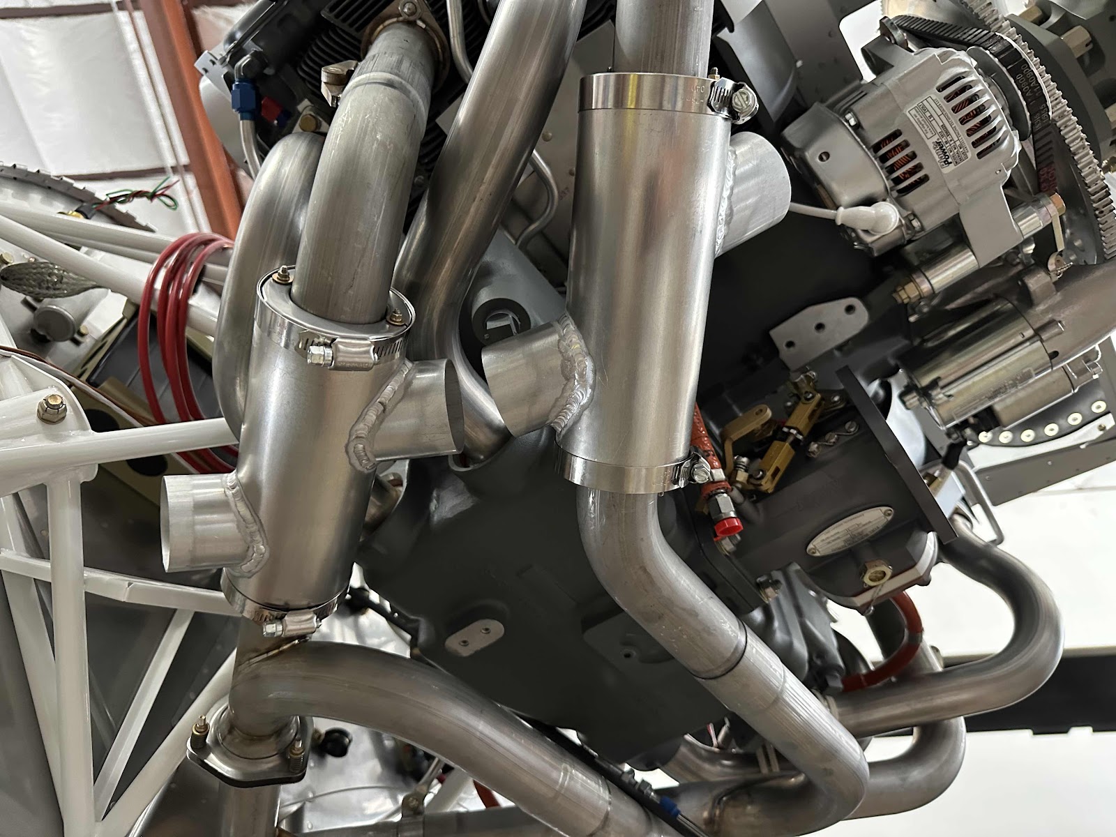
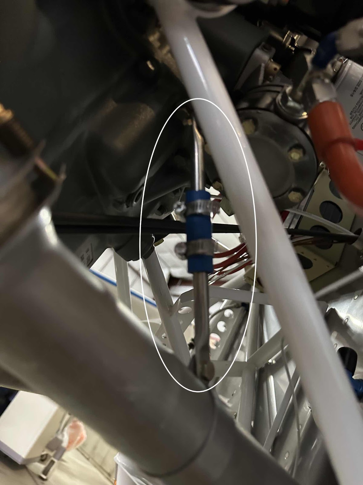
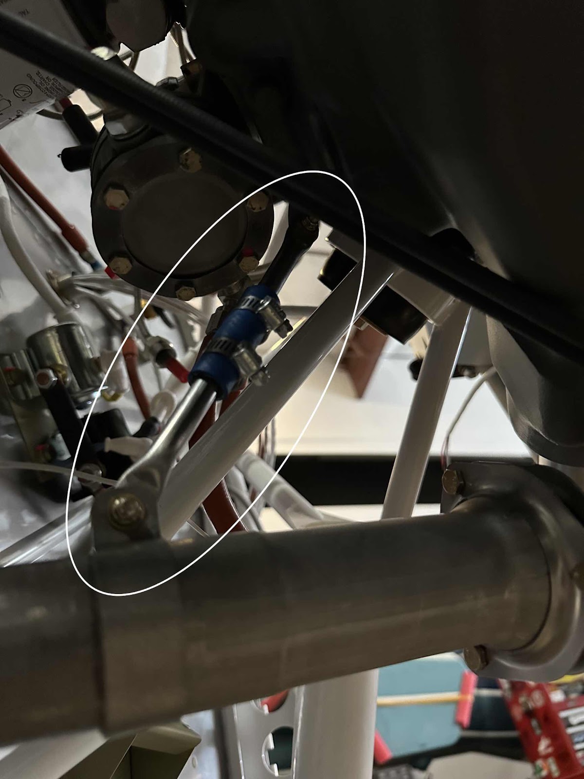
One of the tubes is bolted to the Oil Sump and the other tube is bolted to an Exhaust Hanger Bracket. The tubes are then joined together by using a length of rubber hose secured by two stainless steel hose clamps. As mentioned earlier, the idea behind flaring the opposite end of the support tube is to create a lip preventing the rubber hose and hose clamp from sliding off the tubes.
**Regarding the flared end of the tube: the instructions say to use a vice to compress the end of the tube (to values shown in the plans), thus making the lip. I’m sure the process works fine, but I didn’t really like it. So, since all that is needed is a lip, I used a tube flaring tool to create a perfectly round lip all the way around the tube. (Be careful not to make the flare to large or it will be difficult to insert it into the hose). I liked the outcome this process produced on the tube. The pictures below show a couple views of the completed and installed Forward Exhaust Hanger Assembly.
Next, I installed the Heat Muff Assemblies. The assemblies are installed by first connecting the two stainless steel rods to the four Heat Muff Ends (two separate pieces make up each end). The plans specify the length from the outside edges of the Ends should be approximately 7 3/8”. The assembly is held in place by friction resulting from bending the inner “teeth” of Heat Muff Ends inward to create a tighter clamping force when the rods are installed. This is the forward assembly….the rear assembly is installed in the same manner.

The Heat Muff Skin is now installed around the assembly and secured with stainless steel clamps around the Heat Muff Ends. This is also the Forward Heat Muff.

This picture shows the forward and aft Heat Muffs completely installed. There are six sections of Scat Hoses that now need to be installed. I will wait until I finish running all the control cables, wires, etc before I install them to allow space to work.