Monday, April 6, 2020

Interior Paint (Part 2)

In Part 1, I talked about which interior paint I chose and why.  Afterwards, I applied that paint to several of the parts that I had previously prepared and primed.  I was very, very happy with the way they turned out.  So, I moved on to painting the Instrument Sub Panel.  Now, I will admit it would have been unbelievably easier to paint the assembly BEORE riveting it to the plane.  However, I did not.  Anyway, I taped off the Sub Panel and sprayed it with the SEM paint.  Here is what it looked like after I applied the two coats.  

This view looks from the cockpit forward at the assembly.....

.....the right side of the assembly.....

.....and the left side of the assembly.

So far, I’m very please with how it turned out.  Eventually, the Instrument Panel Frame will attach to the two Ribs in the center of the Sub Panel and to the Longerons with additional brackets.  I painted this area specifically because.....when the Canopy is attached and in the up/open position, you will be able to see this area.  This area will also be open to access the rear of the installed Avionics.  So, since it will be visible, I wanted the color to match the rest of the plane scheme.  The areas forward of the Sub Panel will be covered with a Forward Skin and will not be visible.....so, the Akzo green primer will be sufficient.

Saturday, April 4, 2020

Interior Paint (Part 1)

It’s time we make some final decision regarding paint color.....at least for the interior (that can later be complemented by exterior paint and colors).  

My decision process for interior paint:

To Start:  We have already begun the initial stages of coordination with Classic Aero Designs for the interior carpet, seats, and side panels for the airplane (only for material type and color selections at this point which will be covered in later blog postings).  That initial coordination will/did help with the interior paint color selections.  After researching many options, we have decided to go with SEM Products.  I originally had no knowledge of the product, but they were recommended by my A&P buddy.....so, I tried them out.

Some Information about SEM Products:

If you look under the Aerospace Tab on their website, they show several products.  I decided to go with the Color Coat Aerosols.  Now, when you initially look at the Color Coat product it says it’s designed to paint vinyl surfaces, flexible and rigid plastics, carpet and velour.  However, the 
Color Coat Technical Data Sheet also lists “properly prepped and primed metals” as suitable substrates.  Now, maybe I missed it, but I couldn’t find on their website what they consider a “properly prepped” metal.  So, I looked at several automotive blogs (since this product is use heavily in the automotive industry) that utilize the Color Coat product.  The predominate recommendation for metal prep was to scuff the metal surface’s original paint or primer with grey Scotchbrite and clean with a wax/grease remover.  Then, it’s ready for the paint.  Seems easy enough.  We will see how it goes.

We initially decided on four different colors from the Color Coat Color Card to sample:

1.  15393 - Medium Gray
2.  15763 - Storm Gray
3.  15253 - Titanium Metallic
4.  15183 - Warm Grey

These four particular color come in 12oz spray cans and here they are.

I had an old Flap Skin that I replaced while building Section 21.  The “scrap” Flap Skin had already been treated with Alumiprep, Alodine and Akzo primer, so it was the perfect test piece to use.  I cleaned up the Flap Skin and sprayed each color on a section of the Skin.  In the picture below, you can see the results from each of the four colors (in the same order as listed above marked #1 - #4).  Due to the green Akzo primer underneath it, each one of the paints had to have a second coat applied to “hid” the green tint of the primer.  Colors #1, #2, and #4 went on very smoothly and uniformly.  I guess because of the metallic in #3, it seems to streak and the tip splattered a little.....maybe I just didn’t do it right.   Anyway, #2 and #4 we thought were a little to light and #3 was eliminated due to the reasons I mentioned above.  Sooooo, #1 - Medium Gray it is......

As I mentioned, each piece needed two coats because of the green Akzo primer under it.  Here are the left and right Aft Canopy Decks after getting sprayed with the SEM paint.....

.....the left and right Forward Canopy Decks.....

.....Instrument Panel Attach Brackets (top center), Cable Support Bracket (center), Wiring Channel (bottom center) and the two Instrument Panel Attach Plates.

Now, another ongoing debate with myself.  Since I am going to install carpet, seats (obviously), and side panels how much of the interior do I paint.

Friday, April 3, 2020

Fuselage, Upper FWD Fuselage (Part 14)

Today’s work session started by separating and preparing the F-01467A Instrument Panel Angles.  The picture below shows how the piece(s) comes from Van’s.....kinda looks like a fish!

Here are the two finished Angles after being separated, holes deburred and edges cleaned.  They are now ready to be treated with Alumiprep, Alodine and Akzo primer.

Moving on to the F-01467 Instrument Panel Frame.  Just like the Angles above, the Instrument Panel Frame had the holes deburred and edges cleaned.  Additionally, there were also ALOT of holes to countersink.....a lot of them!  Most of the countersinks are for AN426AD3-3 rivets that will be used to attach nutplates to the frame.  The prep work is now complete and the Frame is now ready for Alumiprep, Alodine and Akzo primer.


I don’t think I previously mentioned it, but in Part 12 I treated several parts with Alumiprep and Alodine.....now it’s time to Akzo prime.  These are the left and right Aft Canopy Decks.....

.....left and right Forward Canopy Decks.....

.....the Cable Support Bracket (top),  Instrument Panel Attach Plates (middle), Wiring Channel (bottom).....

.....and the left and right Instrument Panel Attach Brackets.

Thursday, April 2, 2020

Fuselage, Upper FWD Fuselage (Part 13)

Today’s session focused on countersinking the holes in the left and right Upper Longeron Assemblies to accept the dimpled #40 holes in the Forward and Aft Canopy Decks.  The Longeron was wide enough that I could use my threaded micro stop countersink to prepare the holes.  As a result, the process was pretty easy.  The hardest part was gauging the appropriate depth to set the cage.....cut, check the depth, cut, check the depth, etc....Once I figured out the depth I thought was appropriate, it went pretty fast.  The first hole on the Longeron (near the Firewall) does not get countersunk and the last hole (near the Gussett) had to be countersunk with my hand countersink cutter.  The Gussett was to close to the hole for the cage to sit flush on the Longeron.

Here is the completed right Upper Longeron Assembly.....

.....and the completed left Upper Longeron Assembly.

Wednesday, April 1, 2020

Fuselage, Upper FWD Fuselage (Parts 11 & 12)

Wednesday, April 1, 2020 (Part 12)

Continuing from yesterday’s work.....

I started today by cleaning more parts.....separating when necessary, deburring holes and cleaning edges.  Here is the F-01494D Cable Support Bracket.....

.....F-01494C Wiring Channel.....

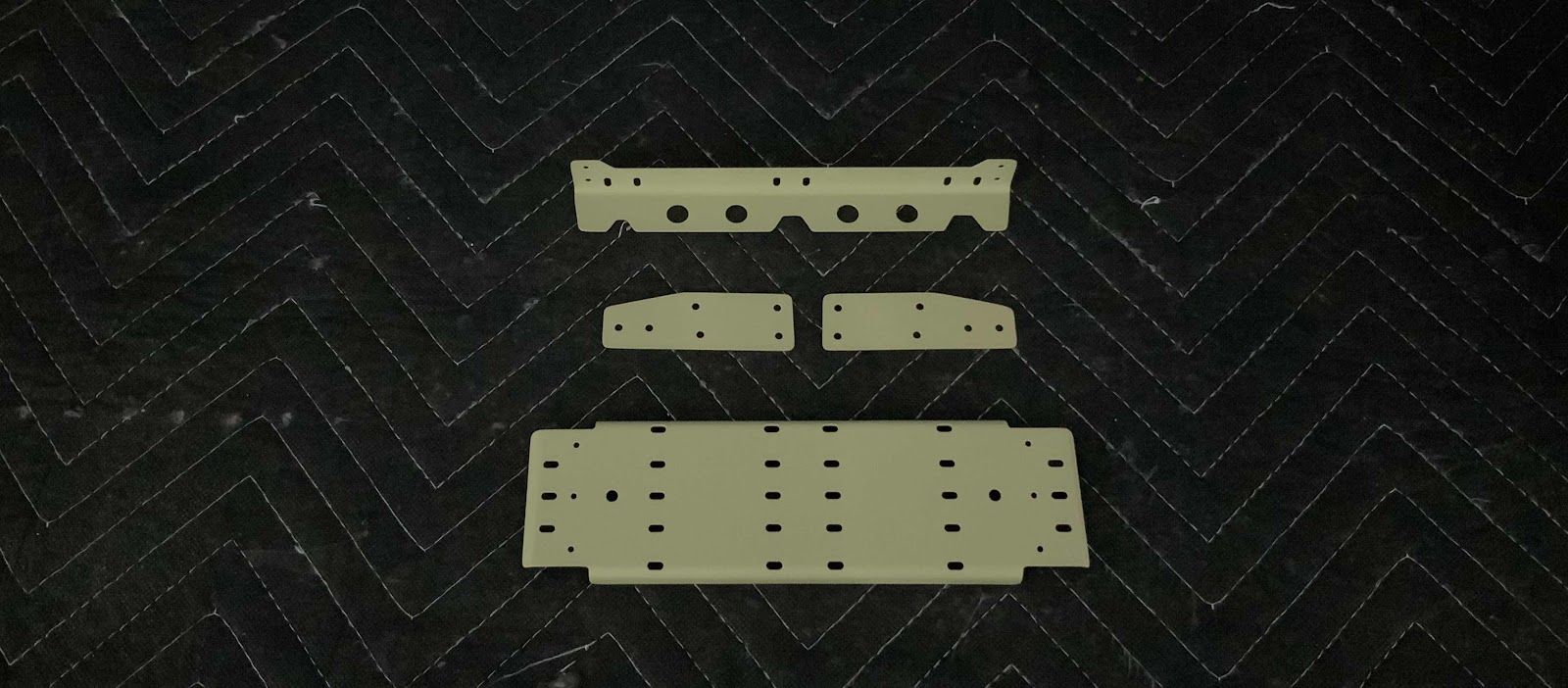
.....F-01468-L & -R Instrument Panel Attach Brackets.....

.....F-01476 Instrument Panel Attach Plates.....

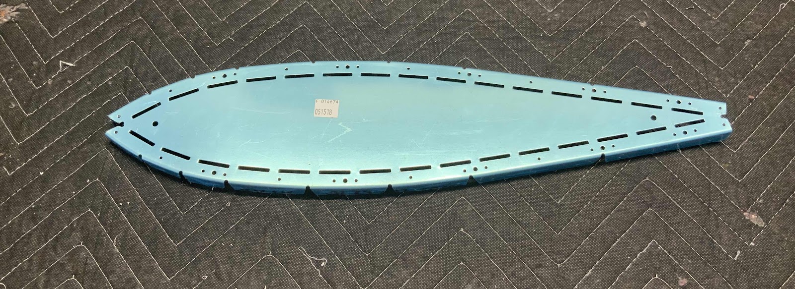
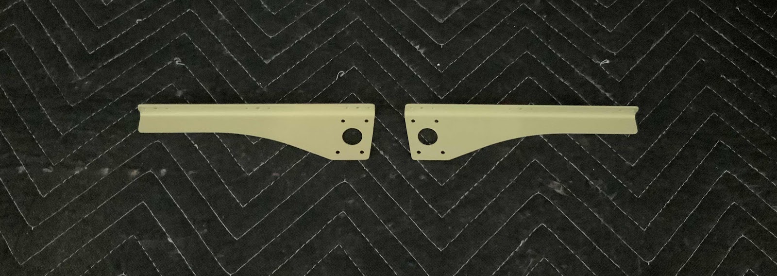
.....F-01421A-L & -R Forward Canopy Decks.....

.....and F-01421B-L & -R Aft Canopy Decks.

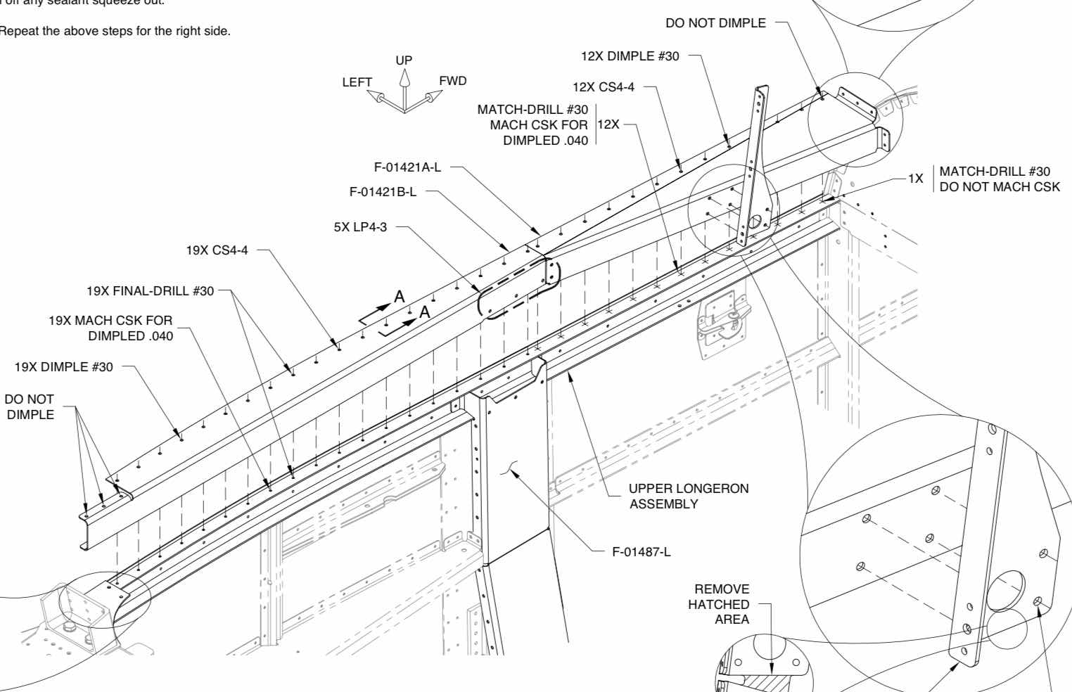
Alright, a lot is going on over the next several steps and the plans excerpt below is pretty busy.

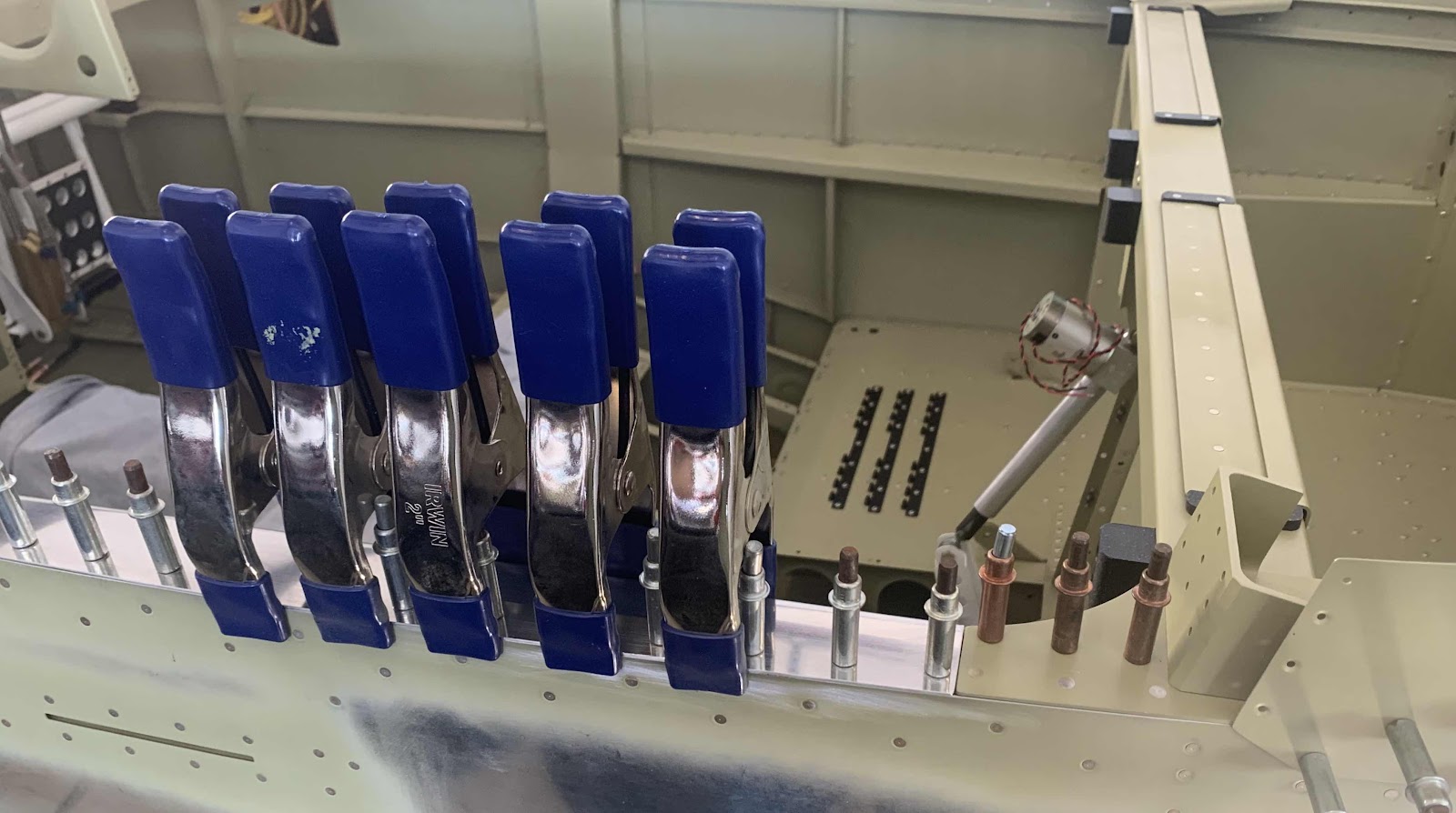
First, the Left Aft Canopy Deck was clecoed to the Upper Longeron Assembly.  The Aft Canopy Deck was then aligned to the outboard edge of the Fuselage Side Skin.  To do this, I used the 2” Irwin blue clamps to “pinch” the Aft Canopy Deck flush with the Side Skin.  I was actually surprised at how perfectly this worked out.  Here is a close up of what it looked like with the five clamps in place.

Here is an overall picture.

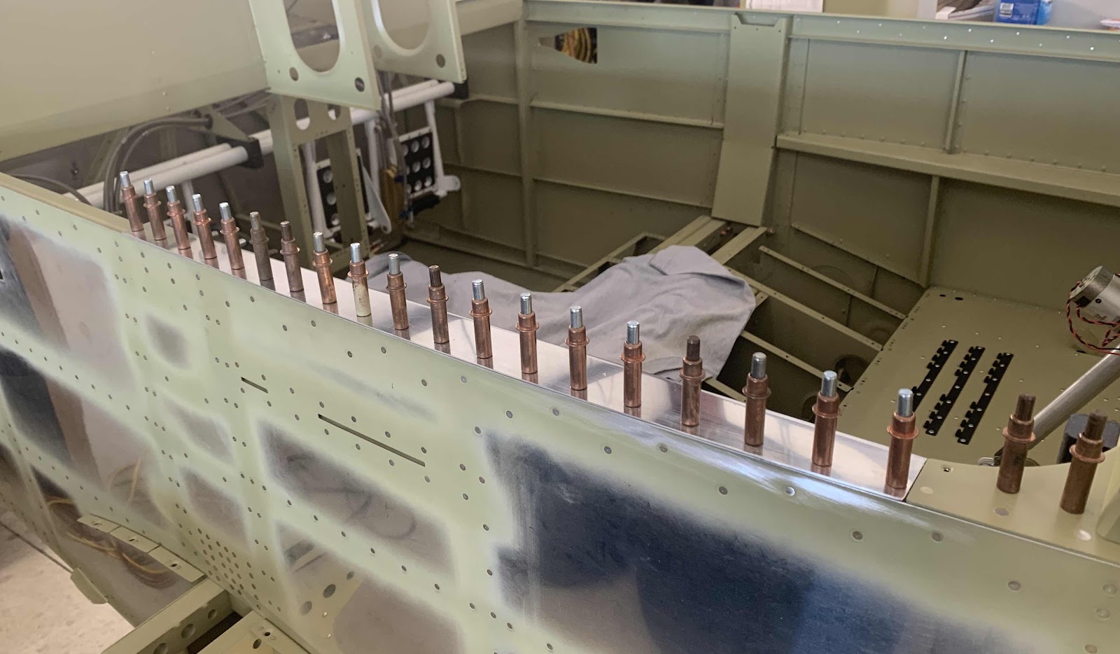
Each one of the holes containing the sliver #40 clecos will need to be final-drilled #30.  To do this, I removed the clamp directly over the hole to be drilled and moved it to the end of the row.  Then, removed the silver #40 cleco, final-drilled the hole #30 and installed a copper #30 cleco.....and repeated that step for all 19 holes.

Here are all 19 holes on the left Aft Canopy Deck final-drilled to #30.

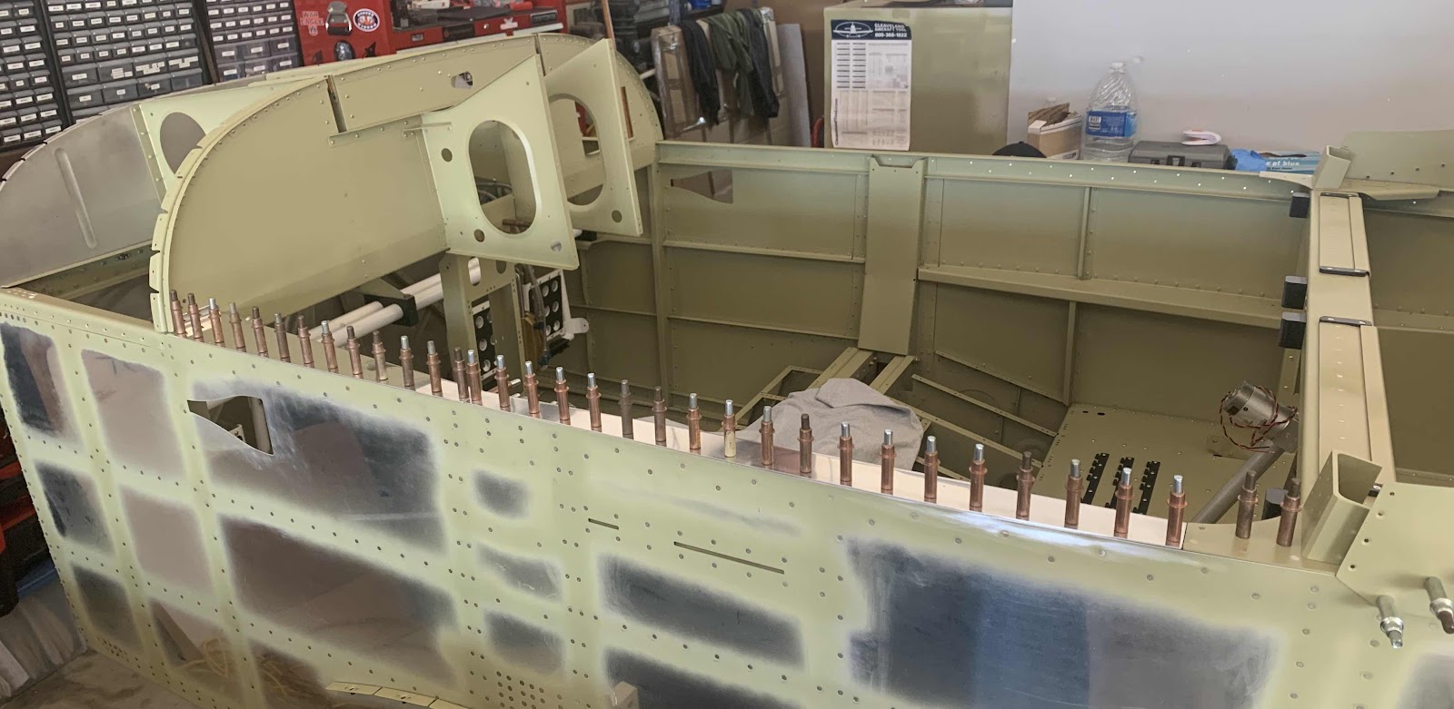
Now, the Forward Canopy Deck was clecoed to the Aft Canopy Deck and Sub Panel.  There are no prepunched holes in the forward part of the Longeron.  So, these holes had to be match-drill #30 using the holes in the Forward Canopy Deck as guides.  The Forward Canopy Deck gets wider as you move forward and doesn’t have holes to install clecos to keep it somewhat held in place.  So, I wasn’t able to use the blue clamps to this piece.  However, I was able to hold the Deck in place with my hand while match-drilling the holes.  This too, actually worked out perfectly.  Here are the Forward and Aft Canopy Decks with all the required #30 holes.

From this angle, you can see how flush the Deck is with the Side Skin.  There is also a little gap near the first several clecos.  This is because of aluminum shavings between the two pieces.  Once I removed the shavings, the Deck sat flush with no gaps.

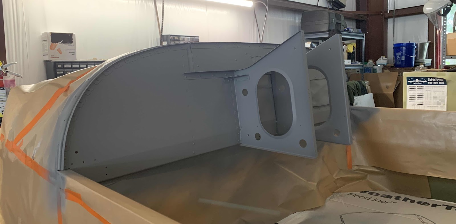
Here is a picture of the inside showing the left Forward and Aft Canopy Decks clecoed into position.

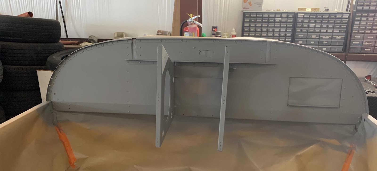
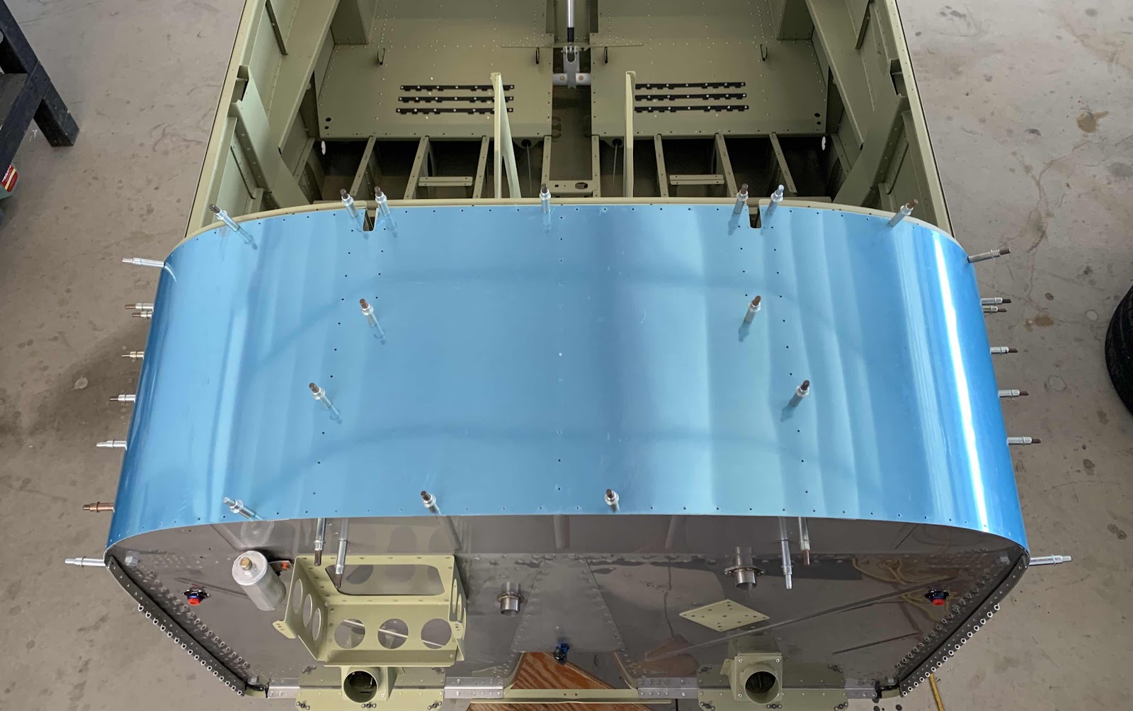
The Forward and Aft Canopy Decks for the right side were prepared the exact same way.  Here is a picture of the outside.....

.....and the inside.

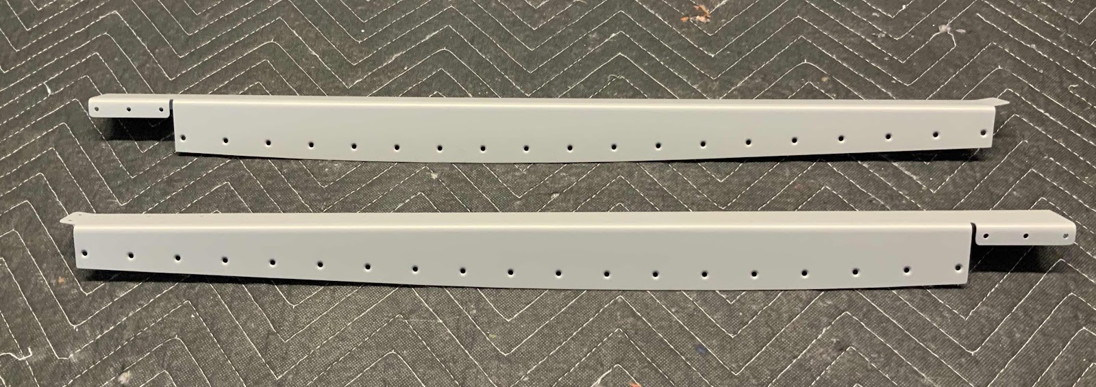
Lastly, here are the completed left and right Canopy Decks.

Session Total:  4.3 / Upper FWD Fuselage Total:  30.0

- - - - - - - - - - - - - - - - - - - - - - - - - - - - - - - - - - - - - - - - - - - - - - - - - - - - - - - - - - - - - - - - - - - - - - - - - - - - - - - - - -

Tuesday, May 31, 2020 (Part 11)

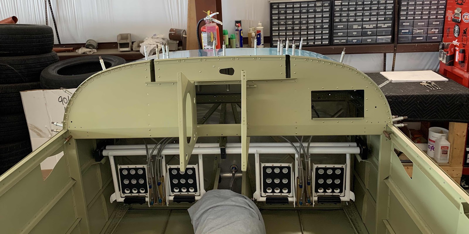
After completing the Upper FWD Fuselage Assembly (“the frame”) in Part 10, it now gets installed/riveted to the airplane.  However, prior to setting any rivets, I wanted to check to make sure it fit on the Fuselage correctly and all the parts had the proper clearances.  So, I temporarily clecoed the F-01471 Forward Top Skin and “the frame” to the Fuselage.....and looked.  Here is a couple views.....


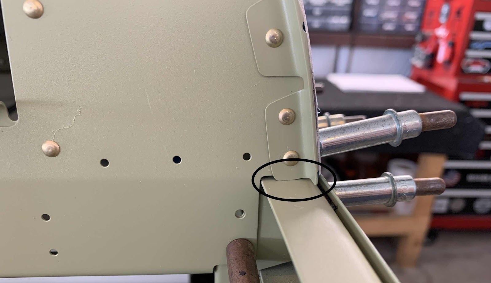
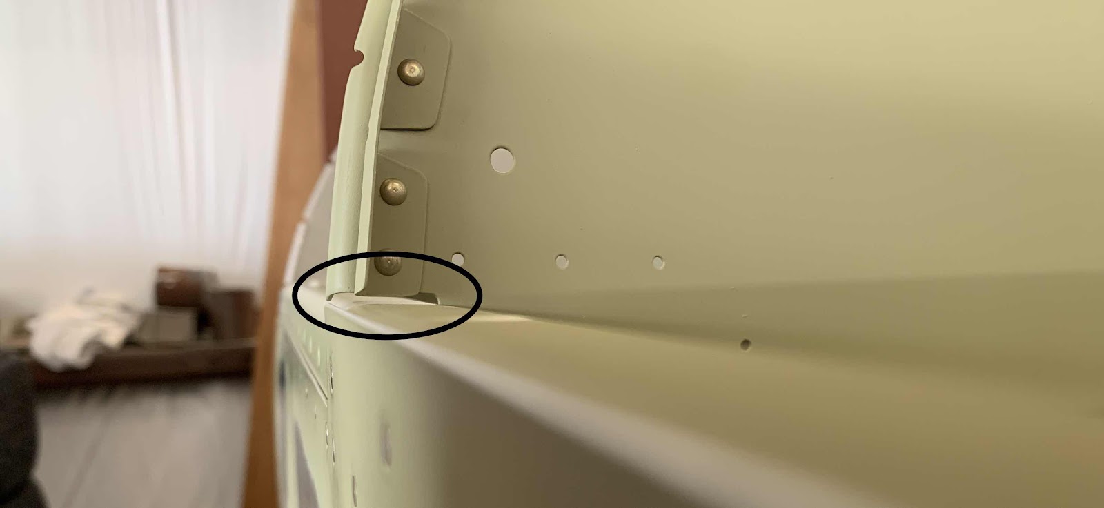
While checking for fit and clearance, I did find two places that needed a little attention.  Circled in the pictures below are the bottom ends of the F-01455C-L (first picture) and F-01455C-R (second picture) Seal Angles where they “meet” the Longerons.  The Seal Angles on both sides rubbed and made contact with the Longerons.


So, I removed “the Frame” and sanded the bottom of the Angles to make the proper clearance.  After re-installing the Upper FWD Fuselage Assembly, there is now adequate clearance between the Seal Angles and each corresponding Longeron.  Here is the pilot left side.....

.....and the co-pilot right side.

Now, I can start riveting Upper FWD Fuselage Assembly to the plane.  This is the left FWD Fuselage Rib riveted to the F-01401A Firewall Top using six AN426AD3-3 rivets and one AN470AD3-4 to the F-01401D Firewall Angle.


The opposite side of the Firewall where the rivets were installed.

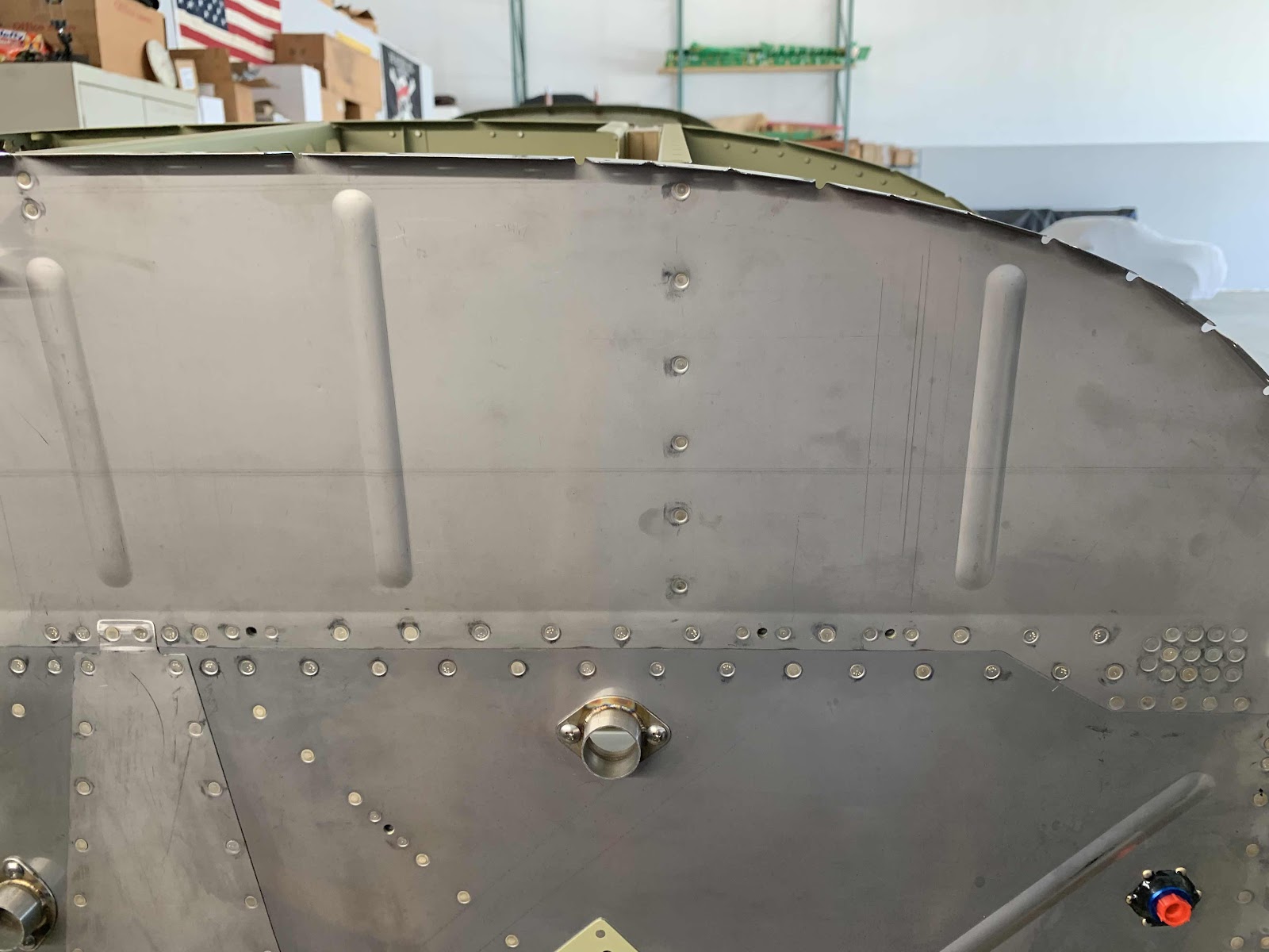
Lastly, for the left side installation....the two circled rivets are the two AN470AD4-4 connecting the Upper FWD Fuselage Assembly to the F-01402-L Side Frame.


The right side was installed the same way and with the same rivets.....to Upper Firewall and Firewall Angle.....


.....opposite side of the Upper Firewall.....

.....and to the Side Frame.


This is the FF-00005 Cowl Pin Retention Bracket attached to the Upper Firewall with two AN426AD3-3 rivets.


Here is the left side of the Upper FWD Fuselage Assembly showing the temporary installation of the C-01440-L Canopy Hinge Bracket.....

.....and the right one.

Finally for this session, I clecoed the the F-14106 Wiring Channel into place between the bottom of the Sub Panel and the F-01451-L & -R Tunnel Sides.