This blog was created to memorialize the building process of my Van's Aircraft RV-14 and to satisfy the requirements for certification in the Experimental Amateur Built Aircraft category. It will also serve as a central location for ME to reference in the future on processes and techniques I used during the build. Additionally, it will allow my family, friends, and other interested builders the opportunity to follow along during my build…..and might be helpful to someone along the way.
Roger and I started the session by sanding a few additional places on the Window.....for just a little bit better fit. Once we were satisfied, we moved on to the next step in plans.
The F-01474A-L & -R Stiffener Angles completed in Part 4 were now riveted to the Side Skins and Rollbar. Since the pictures I took are kind of hard to see, here is the excerpt from the plans showing the install location and hardware used.
These are the three AN426AD3-3 rivets attaching the Stiffener to the left Side Skin (the right side is done the exact same way). I doesn’t look it, but there was plenty of room to get the yoke of the hand squeezer on the shop head side.....carefully pulling the Side Skin out a little.
These are the two LP4-3 blind rivets attaching the Stiffener to the left Side Skin (again, the right is done the exact same way).
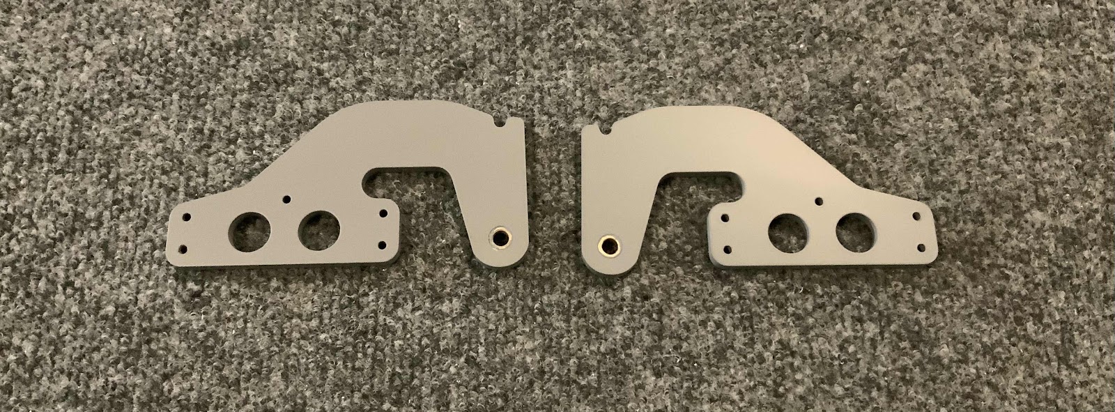
Next, the C-01429 Latch Bellcrank Angles were installed using the hardware shown below in the plans excerpt.
Here are two of the Angles attached to the F-01457 Gusset on the left side (the right side is done the exact same way).....
.....and what it looks like on the underside.
Moving on to the installation of the F-01438 Canopy Latch Torque Tube. Here is the plans excerpt showing the installation.
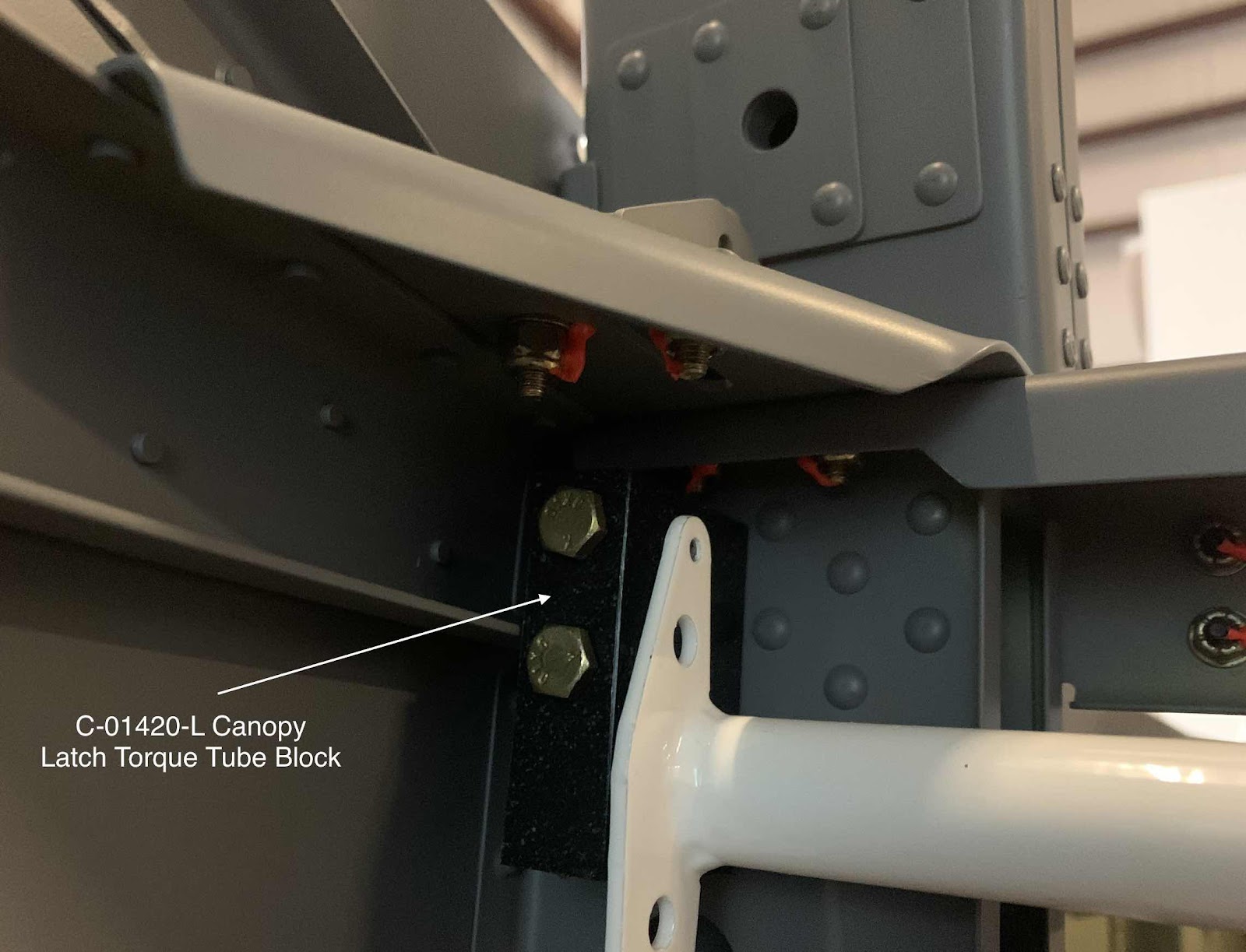
This picture shows the left Block attached.....
.....the right Block attached....
.....and the overall installation of the Canopy Latch Torque Tube.
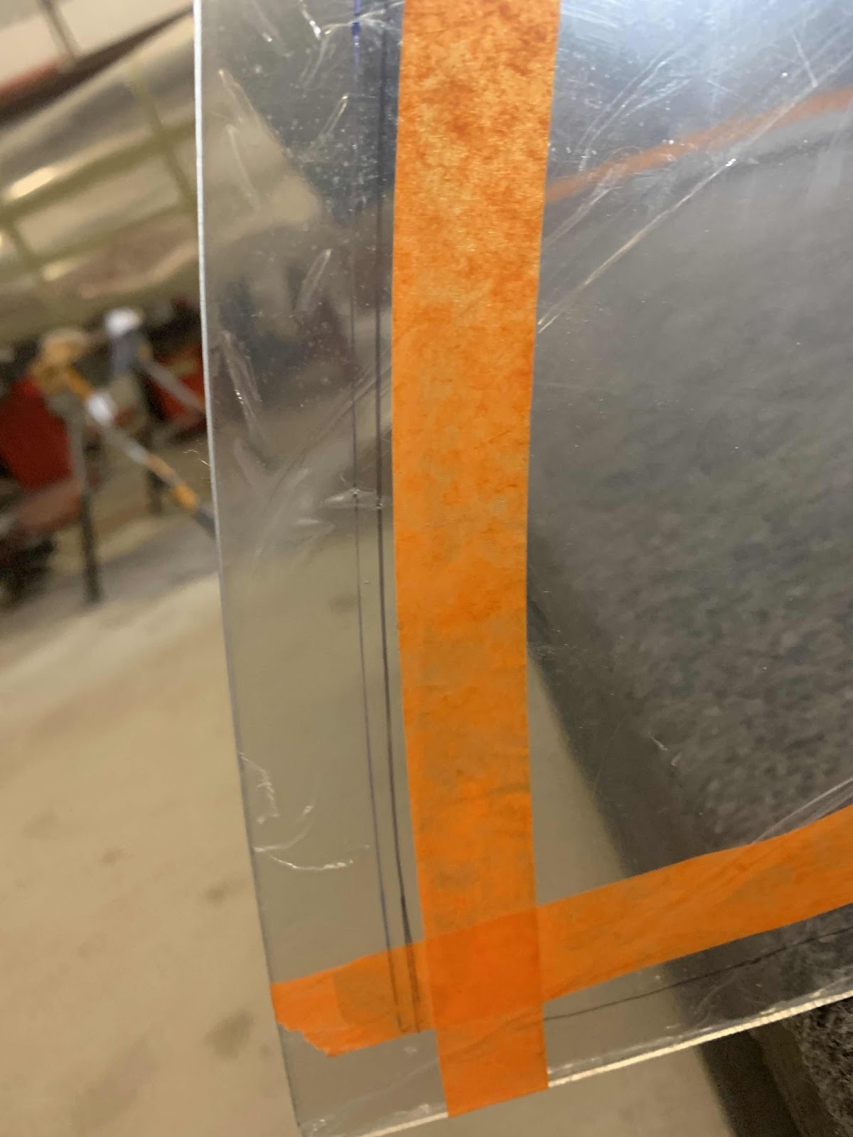
As I mentioned in Part 4, we traced the inside of the baggage area Side Skins onto the protective plastic on the Window. The red line shown below is the correct line and the one we used as a “guide” for the tape. This is how our tape looked installed.
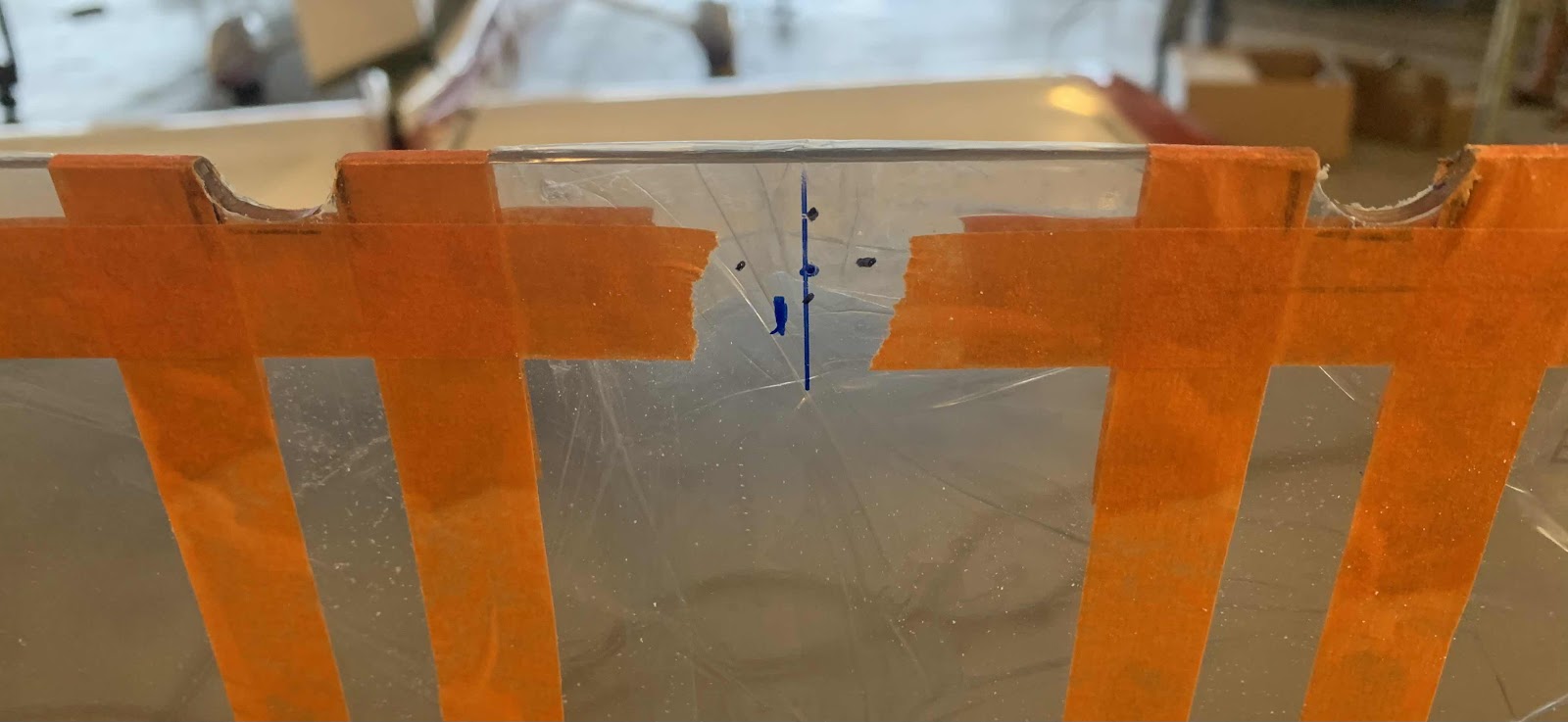
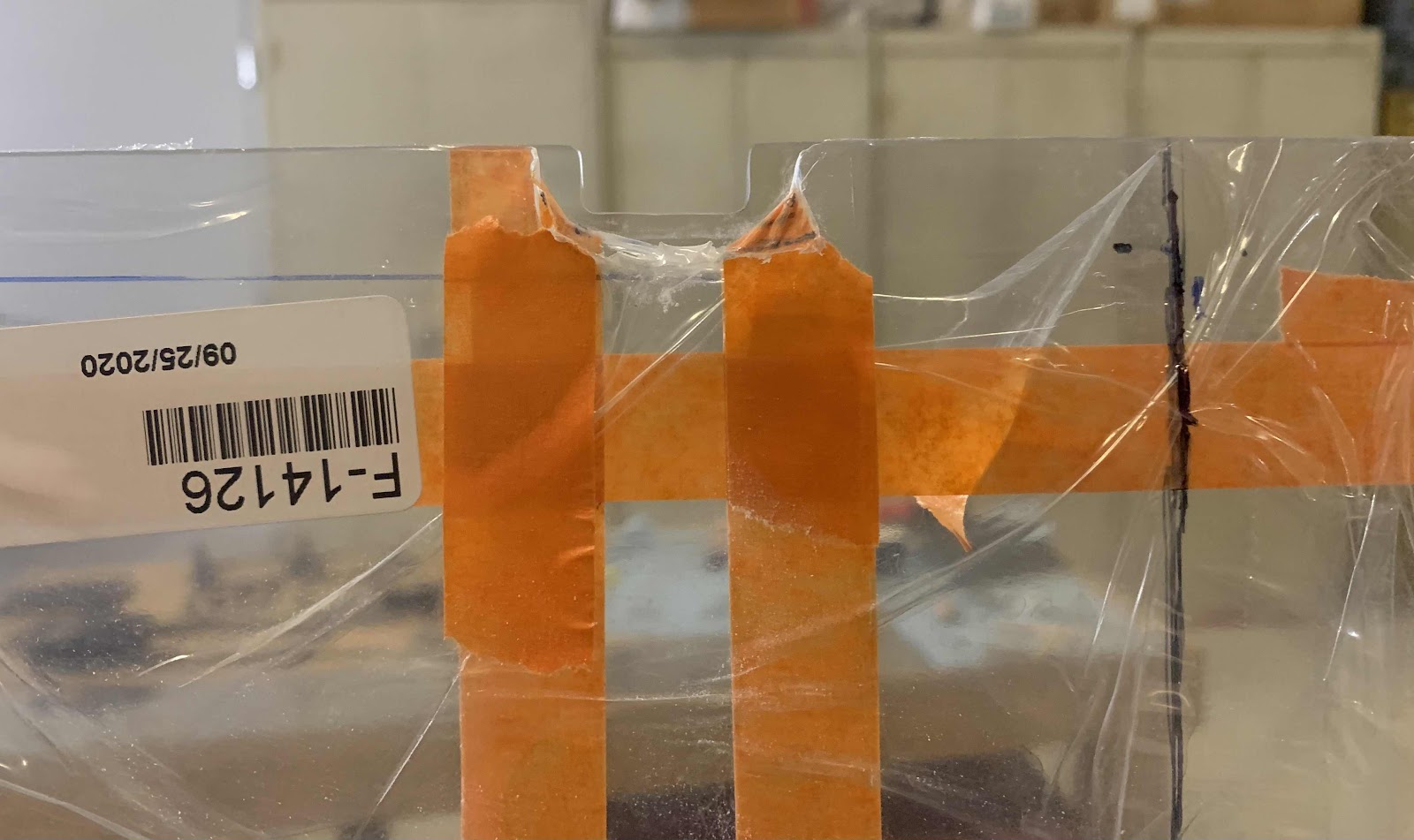
Below are the notches that were described in Part 4. Here, you can see the marks we made on the Window around the Roll Bar Brace Brackets. The area within our marks has to be removed from the Window. Until this point, the only thing we have done with the Window was put in on the plane and use a sharpie to make some marks.....stress free! NOW, it’s time to remove material from the Window.....NERVOUSNESS! (Turned out not to be that bad)
To make the initial cut (round cut shown below), I used the Dremel Sanding Band with my Milwaukee Rotary Tool. As it turns out, the sanding band was exactly the right size to fit between the marks and remove the initial material from the Window. This is the outside of the Window.....
.....and the inside of the Window.
We used my carpeted table set up like this to “stand up” the Window and work on the two notches.
Next, we used a small set of files to file away the reminder of the material. Lastly, we used 320 grit sandpaper wrapped around a popsicle stick to sand for the final shape. Here is the right side.....
.....and the left side.
Here are a couple of additional pictures of both sides of the Window.
My Stepdad, Roger, is now in town to help for about a week and a half. This is the 4th or 5th time he has come down to help with the build and we always get a lot done. I’m excited for him to be here.....awesome way to spend some time with him. I’m not sure how long the Window install will take, but if we can get it installed before he has to leave.....victory! The first step is to position the Window on the Fuselage and push it back up against the Roll Bar Brace Brackets at the rear. I forgot to take a picture when we were doing this, but below is what it looks like in the plans. The shaded area will have to be marked and removed from our Window. Additionally, we had to measure the distance that the Window overhangs the underlying Window Shim on the Roll Bar Assembly along the entire forward edge and make note of the smallest over hang distance. My smallest overhang distance was 8mm. That 8mm (smallest distance) was how “deep” you are supposed to trim the shaded area below on each side.
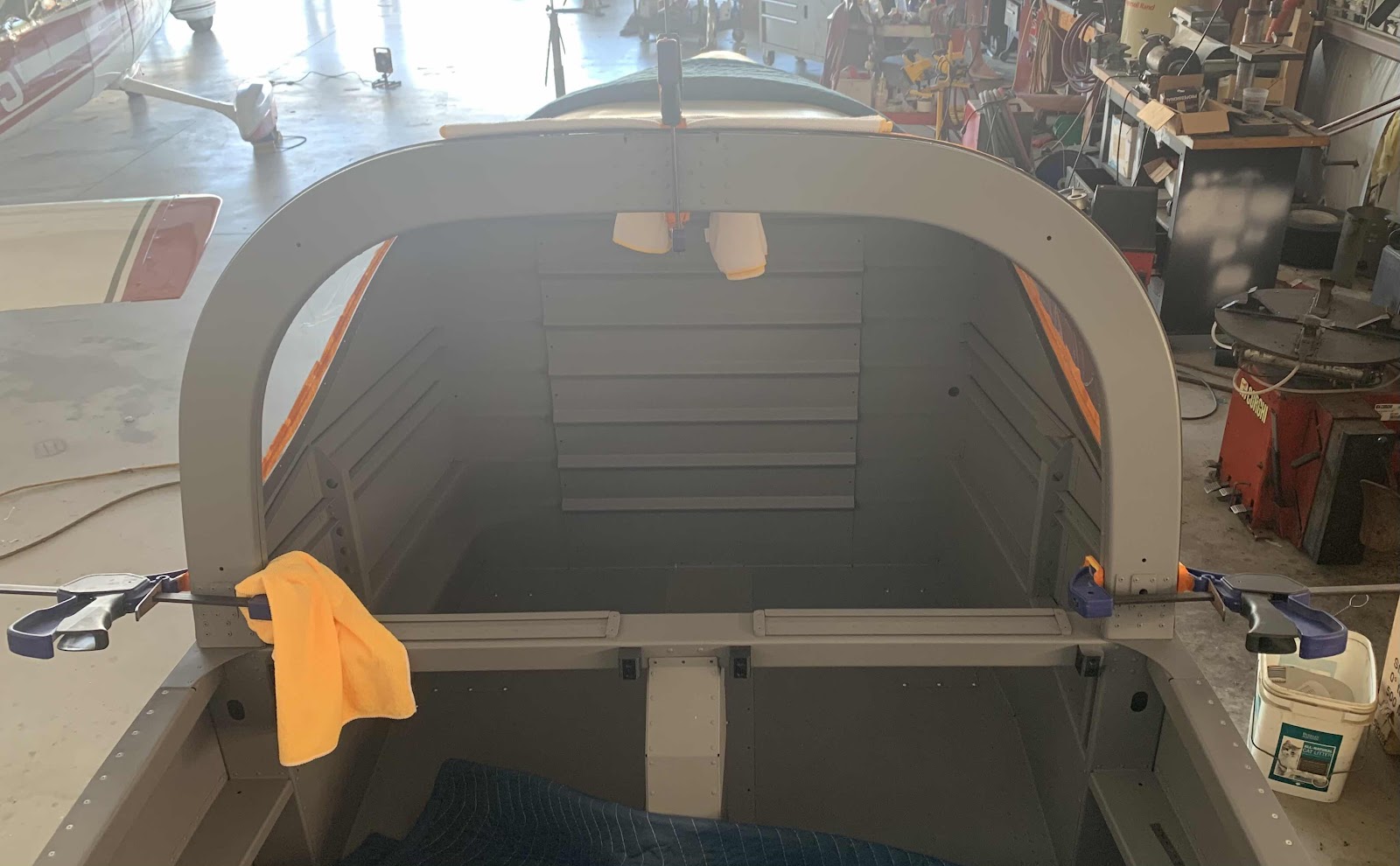
The plans show to use large spring clamps to hold the Window in place against the Roll Bar Assembly. I found and bought some of those clips, but was happy with the way they interacted with the Window. Maybe they weren’t large enough, but I didn’t like them. I have the clamps shown below (used with a soft spacer between the actual material) and found they worked pretty well. Just to be sure, however, I did take about a million measurements to make sure everything was in the proper place and didn’t shift at all.
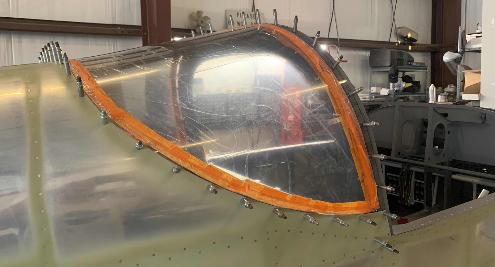
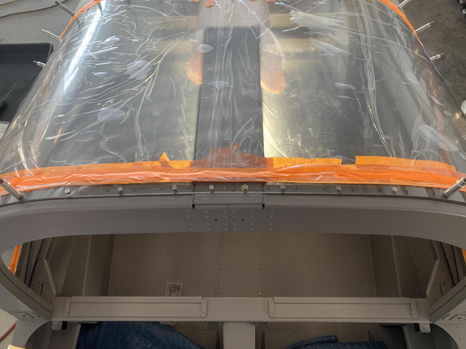
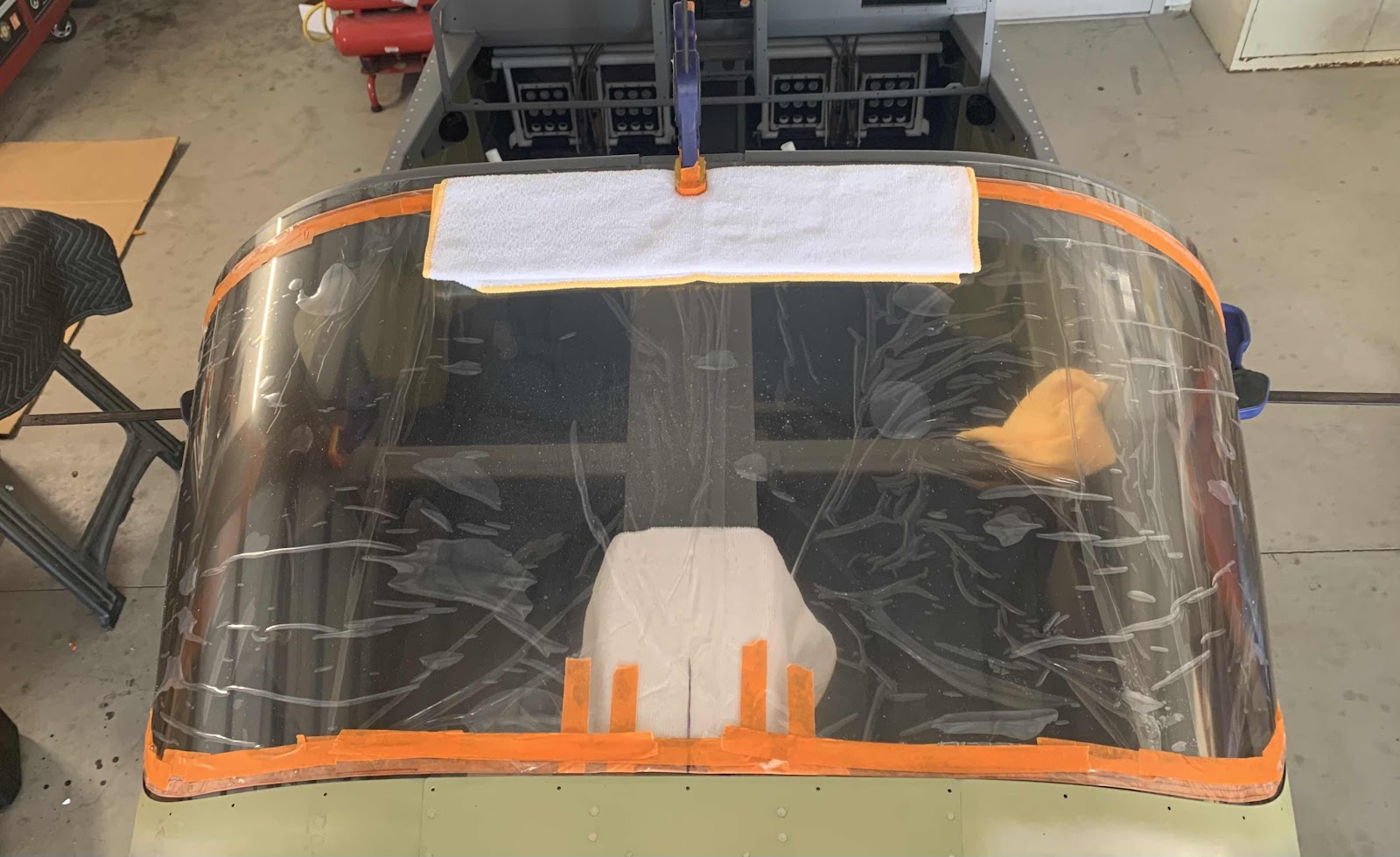
Here is the view from above looking down on the Window. If you notice at the rear of the Window is a vertical line that runs forward from the center rivet hole on the Top Skin. When the Window is shipped from Van’s a center point is marked on the Window. This center point is to be matched up with center rivet hole in the Top Skin during the fitting process. Until we had the correct fitting, I found it hard to see the marked center hole in the Window through the rivet hole. So, I “extended” the mark with a ruler and sharpie. Obviously, you want the two locations to match up, but this line helped tremendously to get everything close.
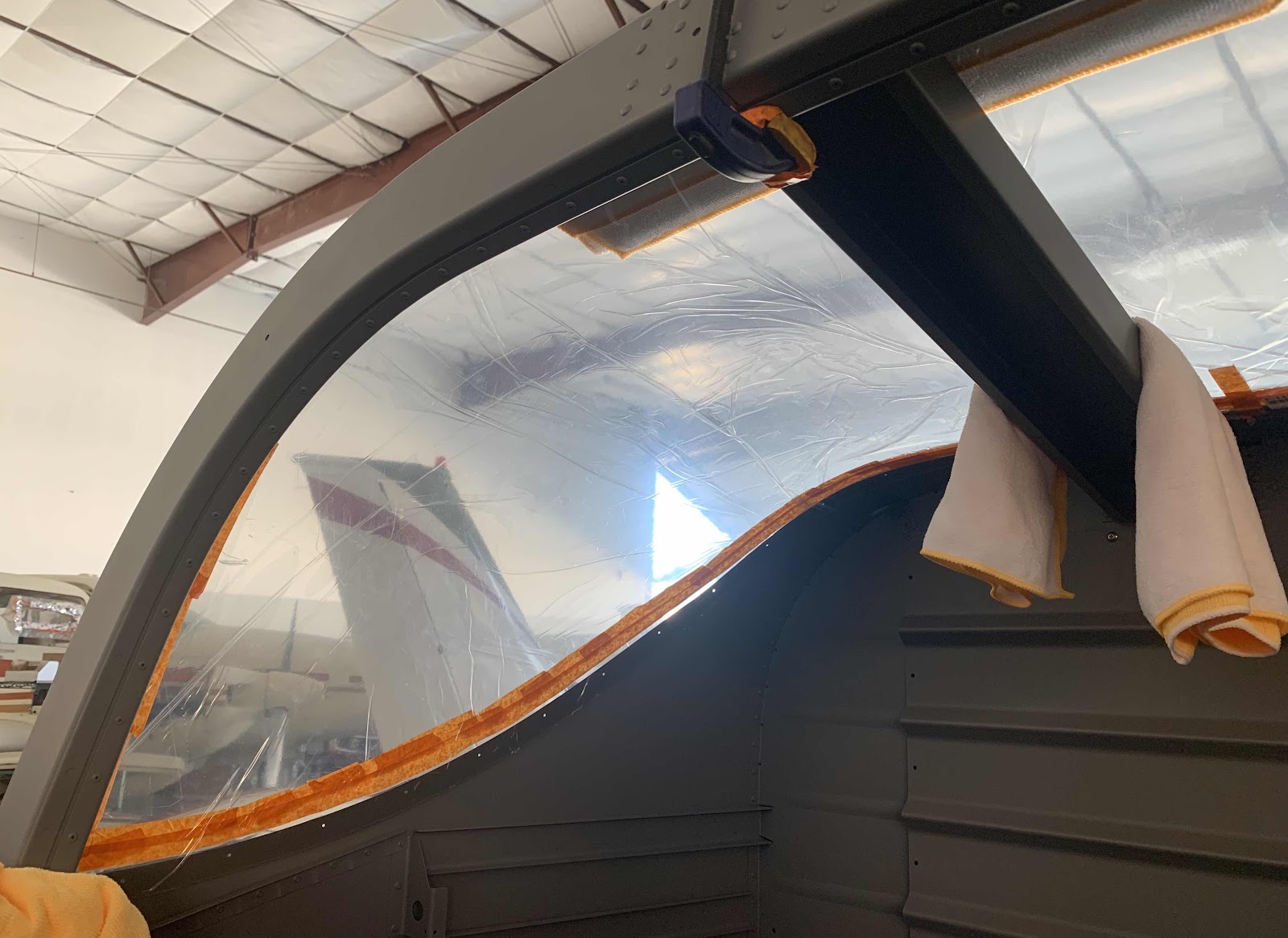
This is a view of the left side of the Window from the inside. To get the Window fit properly, you have to push the lower forward edges of the Window aft in order to force the Window up against the Fuselage Skin to reduce any gaps along the sides. We then had to do two things.....get the most consistent overhang of the Window with respect to the Window Shim (described above) and achieve an equal distance with Side Skins. This area is shown below in the magnified circle. Once all of these areas were as consistent as we could get them, we re-clamped the Window to the Roll Bar.
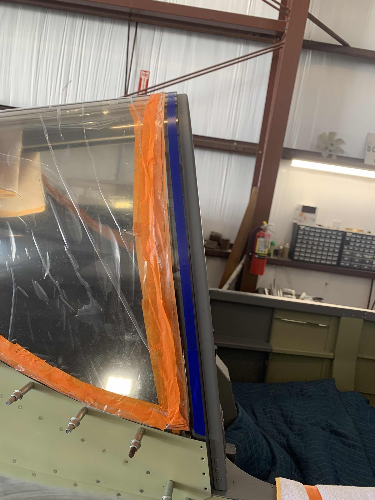
This is a view of the right side.....
.....and the center.
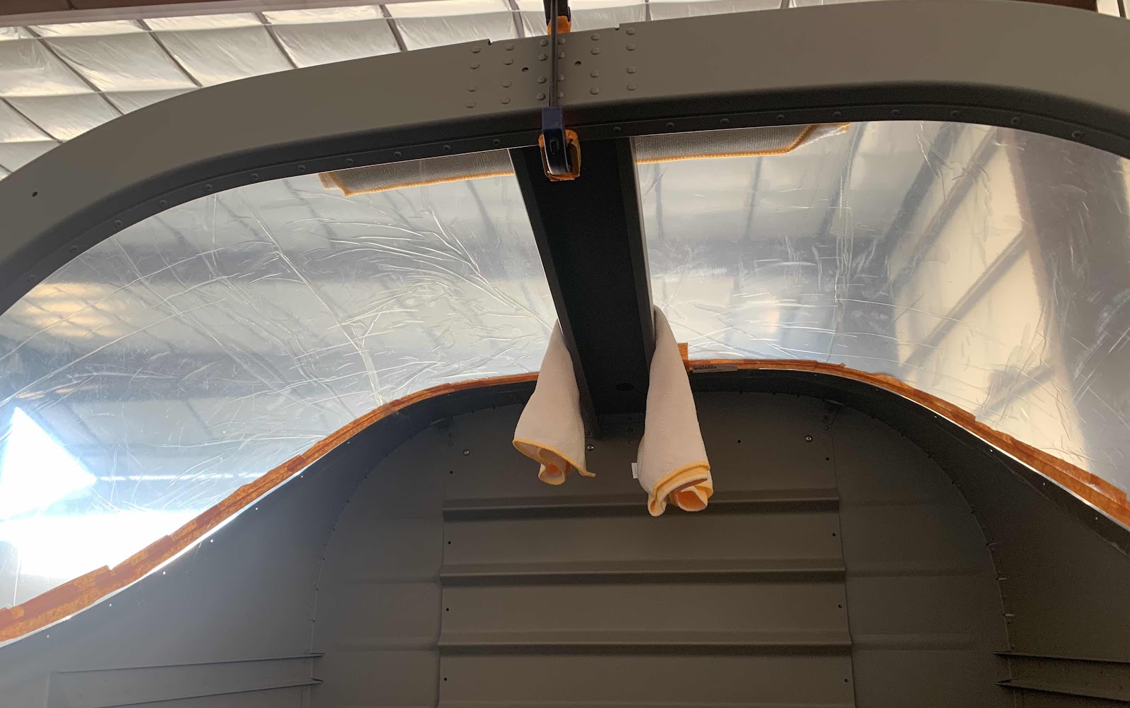
You will also notice the orange tape we put on the Window. The plans had the following NOTE:
“The best fit can be obtained by ensuring that only the bare surface of the window directly contacts the aircraft structure”.
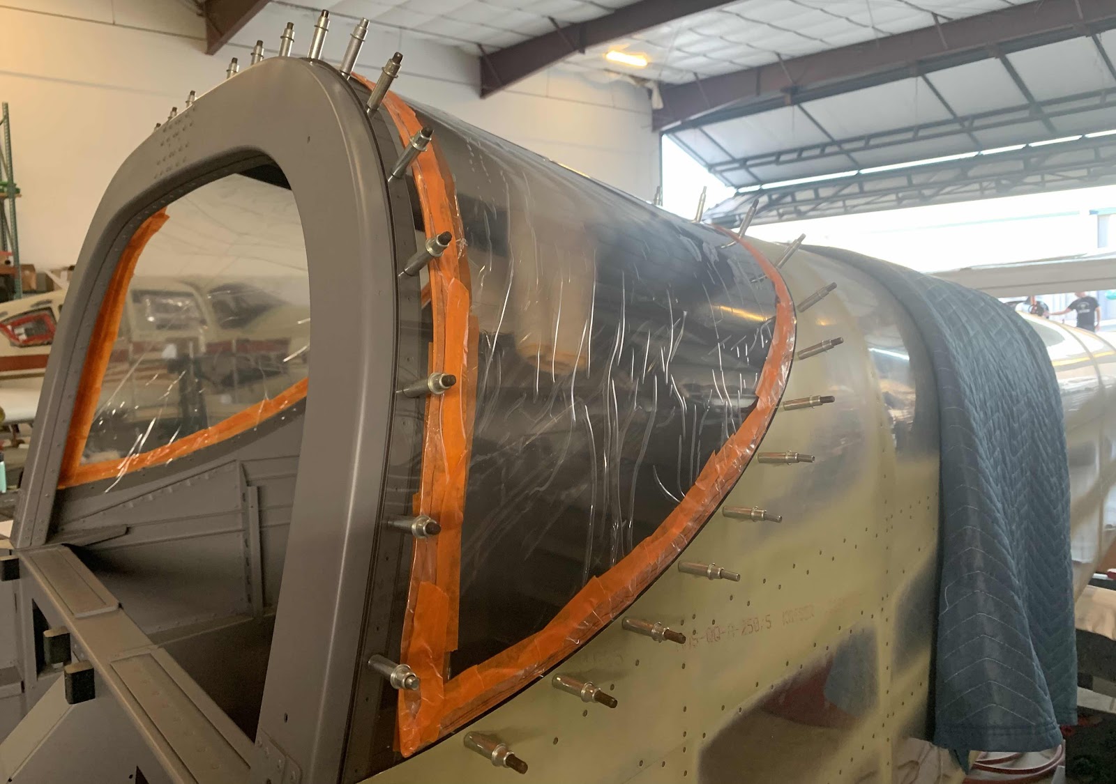
So, with the Window clamped into place, I traced the perimeter of the fuselage skin in the baggage area onto the protective plastic of the Window with a sharpie. Then, we removed the window and peeled the protective plastic back to just beyond that line. Once the protective plastic was peeled back, we installed the orange tape hold the plastic back.....it’s kinda “clingy”.
In Part 1, many parts and pieces for the initial Canopy frame were prepared. During today’s session, I treated them all with Alumiprep, Alodine, Akzo Primer and my grey interior paint. I forgot to take pictures of all the completed parts PRIOR to assembly, so the pictures shown in the post are all post-assembly.
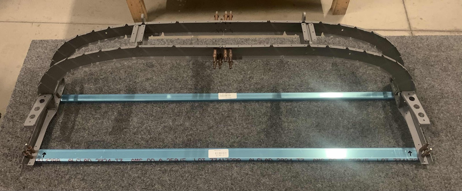
Here is the overall portion of the Canopy Frame that was built during this session. The small blue angle near the forward side of the assembly is the C-01442A Forward Canopy Fixture and the larger one on the aft side is the C-01442B Mid Canopy Fixture. These two “fixtures” are jigs that will be used to help keep the Frame as square as possible during the assembly.
This is the forward side of the picture above.
Since I forgot to show the individual parts after primer/paint, I listed them out in the next few pictures. Here is the left side of the assembly riveted together....
1. C-01402-L, Forward Canopy Frame
2. C-01403-L, Mid Canopy Frame
3. C-01415-L, Forward Intercoastal
4. C-01416-L, Aft Intercoastal
5. C-01408-L, Forward Canopy Rail Base
......and the right side of the assembly riveted together.
These parts make up the left Canopy Hinge Assembly and are riveted to the Frame:
6. C-01414, Outboard Hinge Intercoastal
7. C-01413, Inboard Hinge Intercoastal
8. C-01412, Left Canopy Hinge
The rivets that attach the Intercostals to the Frames were a pain in the ass.....for me anyway. Because of the manufactured and shop heads of the rivets located in the webs of the two pieces, I wasn’t able to get the sets in my hand squeezer square on the rivets. So, I ended up just using my gun and bar to shoot them. Surprisingly, that method turned out to be much easier and produce a great result.
Here is the right Canopy Hinge Assembly. (Shot the rivets on this side also).
The clecos below are temporarily holding the C-01428 Canopy Frame Splices to the Frame. Here is what they look like from the plans.....
Lastly, these are the two C-01412 Canopy Hinge Assemblies that were originally prepared in Part 1. Here, they are ready to be installed following treatment with Alumiprep, Alodine and Akzo Primer.