Sunday, September 30, 2018

Wings, Bottom Wing Skins (Part 11)

Today’s session concentrated on installing the Dynon Avionics Heated AOA/Pitot Probe Mounting Bracket on the bottom of the Left Wing.  I will need to do a little “modifying” for it to fit the RV-14.  The Mounting Bracket I purchased from Dynon is advertised for installation on the RV-7, RV-8, RV-9, and RV-10 and came with installation instructions for those models.  I called customer support at Dynon regarding installation instructions for an RV-14. They were very helpful, but currently do not have any documentation for the RV-14 install.  So, I will have to figure it out.  It doesn’t seem like a huge deal, I’ll just need to use some brain power.

I searched my photos from Sun-N-Fun 2018 and found this picture of the pitot installed on Mitch Lock’s RV-14A.  I’m pretty sure it’s a Garmin Pitot Tube, but the mounting bracket is installed in the same location.  I will use this as a reference for my install.

So, here is what I’m talking about.  Pictured below is the template provided with the Pitot Mast.  In the white box, you can see the four holes for the template and the four holes for the Spar don’t line up correctly.  So, that portion of the template will not work for the RV-14.  However, the remaining rivet hole locations on the template for the Skin attach should work with no problem.  Additionally, I have marked the rivet with a black dot where the plans would have you put the Pitot Tube if you were using the AT0-035X1/4 aluminum tubing.  The rivet is located underneath the third template hole on the Spar.

By looking at Mitch’s install and studying the location on my plane, here is what I’m planning for the install.  

*****For reference purposes only, I taped the Pitot Mounting Bracket ABOVE the three rivet holes I will use for installation***

If you line up the Bracket centerline with the rivet hole below it, you will have three rivets (white rectangle) to use for the installation through the Spar.  This will also get you close to the adjacent Wing Rib (blue tape) for the angle bracket that gets installed inside the Wing (from the Wing Rib to Pitot Bracket).

To complete the installation, the bottom portion of the Pitot Bracket that attaches to the Spar will have to be trimmed to clear the rivets used to attach the Outboard Leading Edge to the Wing Spar.  The area on the Pitot Bracket with the white rectangle (distance between the spar and offset on the Mounting Bracket) measures 0.082 inches.

Initially, I will trim the 0.082 inch front the white triangle below.  Then, I will continue to trim the Bracket until the three mounting holes are in the middle portion that will be riveted to the Spar.


I will pick it up here at the next session.

Saturday, September 29, 2018

Wings, Fuel Tanks (Part 29)

I’ve waited a few days for the Proseal to completely dry on the Right Fuel Tank from the last session.  Now that it has dried, I will leak checked the Ribs portion of the tank with some Avgas.  In the picture below, I have added fuel to just below the last rivet on the aft side of the Tank Ribs (just below the Vent Line on the right side).  Now, I will wait a few days to make sure there are no leaks.


While the Right Tank is sitting, I moved back to the Left Fuel Tank.  The rear Tank Baffle and Zee Brackets were riveted into place during a previous session.  I want to put Proseal on the outside of the rear Tank Baffle and Zee Brackets.  Initially, I brushed adhesion promoter on the dried Proseal from the initial install of the Baffle and Zee Brackets.  After waiting the required 30 minutes, I mixed up some Proseal and brushed it along all the seams and rivet lines.  The Proseal I added is shown below in black.  Now, I’ll wait a few days for the Proseal to dry. 

Tuesday, September 18, 2018

Wings, Fuel Tanks (Part 28)

Jeff and I continued work on the Right Fuel Tank during this session.  Tonight, we riveted and prosealed the T-00003 Tank J-Stiffener, T-1003B-R Tank Inboard Rib-AFT, and T-00006 Tank Attach Bracket Subassembly.  In the picture below, the Rib and Tank Attach Bracket clecoed into place on the Right Tank.

And here is the same picture after setting the rivets and Proseal.  Additionally, on the inside edges of the Tank Skin, you can see several of the K-1100-08D nutplates after installation.

Lastly, this is the view looking down into the Right Tank on the inboard side.  Several things are visible from this view:

—The Fuel Tank Vent Line in the Upper portion connected to the Inboard Rib-AFT with the blue nut
—The inboard portion of the J-Stiffener (under the Vent Line) riveted and prosealed
—The Tank Attach Bracket on inside of the Fuel Tank riveted and prosealed

I will need to clean up some of the Proseal “mess”, but first I will let the Proseal dry for a few days.  Once the Proseal dries, I will leak check it in the same way I did the Left Wing.....by adding 24 gallons of avgas.

Monday, September 17, 2018

Wings, Bottom Wing Skins (Part 10)

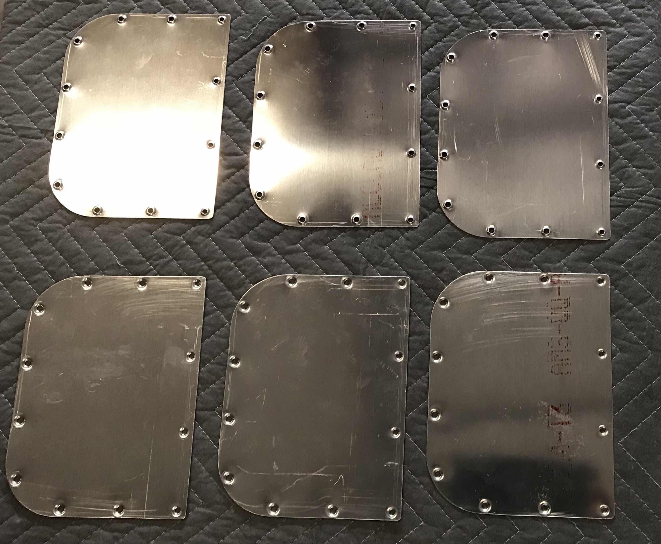
To keep the momentum going, I prepared the six W-822PP Wing Access Plates.  The forward row of holes were Final-Drilled to #28, deburred, and dimpled to accept #6 screws.  The remainder of the holes were Final-Drilled to #19, deburred, and dimpled to accept #8 screws.  I also cleaned all the edges with the Scotchbrite Wheel and 220 grit sandpaper.

The six Access Plates are ready for Alumiprep, Alodine, and Akzo Primer.

Wings, Fuel Tanks (Part 27)

As with the Left Fuel Tank, the Right Fuel Tank will also get a Vent Line.  Today, I installed the 54 1/16” long Fuel Tank Vent Line fabricated from AT0-032X1/4 Soft Aluminum Tube.  An AN818-4D nut and AN819-4D sleeve was place on the inboard side of the Vent Line and it was flared to 37 degrees.  Lastly, the AN832-4D Bulkhead Union and AN924-4D nut was installed (temporarily) to the Tank Inboard Rib-AFT as shown in the plans excerpt below.

Here is the installed Vent Line for the Right Fuel Tank.


Sunday, September 16, 2018

Wings, Bottom Wing Skins (Part 9)

I worked on the Bottom Inboard and Bottom Outboard Wing Skins for the Right Wing.  All the edges have previously been cleaned and all the holes deburred.  So, all that remains is to dimple the #19 and #40 holes.  I used the DRDT-2 for a majority of the dimpling, but did use the pneumatic squeezer for many of the holes around the edges.


Saturday, September 15, 2018

Wings, Systems Routing (Part 4)

During today’s session, I focused on the last two “routings”.....the Wing Tip landing lights and the static lines for the Dynon Pitot Tube (heated with AOA).

To begin, pictured below are the Aeroled’s Aerosun VX landing/taxi/recognition lights designed for the RV line of aircraft.  These lights draw 60 watts of power and generate a combined 13,300 lumens of light.  The lights include a built-in wig-wag controller for a synchronized recognition light mode.  These are additional/optional lights that I have chosen to add to the my lighting system.  These lights will work in conjunction with the Aeroled Sunspot 36’s that will be installed in the outboard leading edge of each wing.

The fairings (known as a conversion kit) shown below were also ordered with the lights.  This conversion kit is required to enlarge the lighting cove to accept the Aerosun VX lights.  This conversion kit is required for the RV-10 and RV-14 if the Aerosun VX will be used.  (This installation will be covered at some point later when I complete the fairing work).

Here’s a video of the “extra” landing light wire run in the Right Wing.  (I will show the Left Wing static sine runs further down the post).


With the additional landing light wires run and completed, I started working on the Static Line runs.  My airplane will need/use three static lines.....
Blue tubing:  Airspeed (Dynon Pitot Tube)
White tubing:  Angle of Attach (AOA) (Dynon Pitot Tube)
Red tubing:  Static Ports 

The blue and white nylon 1/4” O.D. tubing is shown in the packaging and the red is already installed in the Aft Fuselage (as shown below).  All three were ordered from Cleaveland Aircraft Tool.


Because I am adding the additional Wing Tip Lights and two Static Lines (Pitot and AOA), I had to “modify” four of the Left Wing Ribs.  When I was preparing the Ribs in an earlier section, I drilled 1/2” holes in them to allow for wire and tubing runs.  In the picture below, two of these holes are circled and have plastic grommets installed.  The bottom bundle of wires are for the leading edge landing light (Sunspot 36) and the position/strobe light (Pulsar NS90).  The two white wires are for the optional Aerosun VX landing lights.  The two holes that are circled are to be used for the Pitot static lines.  Since I’m using the Dynon Pitot tube with AOA, I will need to use two static lines.....and two static lines WILL NOT fit through the 1/2 hole.  I debated several different options, but ultimately decided to enlarge the holes on the four associated ribs.

The original holes were drilled to 1/2” and needed to be enlarged two steps on the unibit to 5/8”.  Shown here are the four holes I enlarged.  The holes were then deburred and treated with Alumiprep, Alodine, and Akzo Primer.

After the Akzo Primer dried, I installed these MS-35489-13 rubber grommets.....


.....and “tested” to ensure the proper fit.

After the “test” fit I ran the tubing.  Here is a close up of the tubing installed in the Left Wing with showing the rubber grommets. 

This picture shows the final installation of the static tubing.  The plans called for the tubing to be cut to 8’ lengths.  I cut them to a little over 9’ just to make sure there is enough extra if it’s needed.

Lastly, here is a video showing the installed Aerosun VX wiring and blue/white static tubing.  You can also see the wiring for the ADAHRS, Sunspot 36, and NS90.

Section Complete

Thursday, September 6, 2018

Tuesday, September 4, 2018

Wings, Bottom Wing Skins (Part 8)

In the previous post, I covered the dimpling of the Left and Right Inboard Bottom Skins.  Today’s session completed the dimpling on the W-00005-L & -R Outboard Bottom Skins.  I used the pneumatic hand squeezer to dimple all the holes that could be reached with my 3” in yoke.  All the remaining holes were dimpled using the DRDT-2. 

Pictured below is the Left Outboard Wing Skin.

Pictured below is the Right Outboard Wing Skin.

Sunday, September 2, 2018

Wings, Bottom Wing Skins (Part 7)


During today’s session, I dimpled the W-00004-L & -R Inboard Bottom Skins.  I used the pneumatic hand squeezer to dimple the holes that could be reached with my 3” yoke and the DRDT-2 for all the remaining holes.  Because both Inboard Skins are essentially identical and share the same rivet/dimple locations, I will only show the Left Bottom Skin in the pictures below.  Another reason for showing the Left Inboard Bottom Skin is because it has two very small differences compared to the Right Bottom Skin.  The two differences are:

1.   These six rivet (and dimple) locations circled in black is where the W-00012E Mounting Zee will be installed for the ADAHRS Mount Bracket.  (The J-Stiffener will also be used for this bracket installation.  The preparation for the ADAHRS bracket mount is covered in Post #5 and the installation will be covered in future post).

2.  The small 1/4” hole next to the Access Panel.  This hole will be used later in the build for the outside air temperature probe.....I think.  This hole is located in the area where the ADAHRS will be installed, so it only makes sense for the temperature probe to be co-located in the same place.

This picture shows the opposite side of the Left Inboard Bottom Skin.