
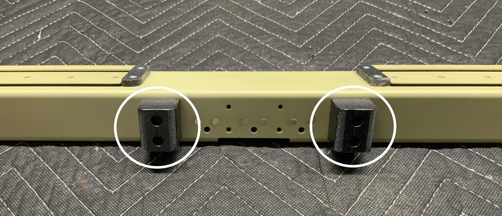
Started today’s session by screwing the F-14144 Seatback Gussetts to the F-01405F Brace. There are a total of four Seatback Gussetts that get installed on the Brace. Pictured below are the the two “inside” Seatback Gussetts. Each of the four Seatback Gussetts are attached to the Brace using two MS35214-31 screws, two NAS1149FN632P washers and two AN365-632A Nylok nuts.
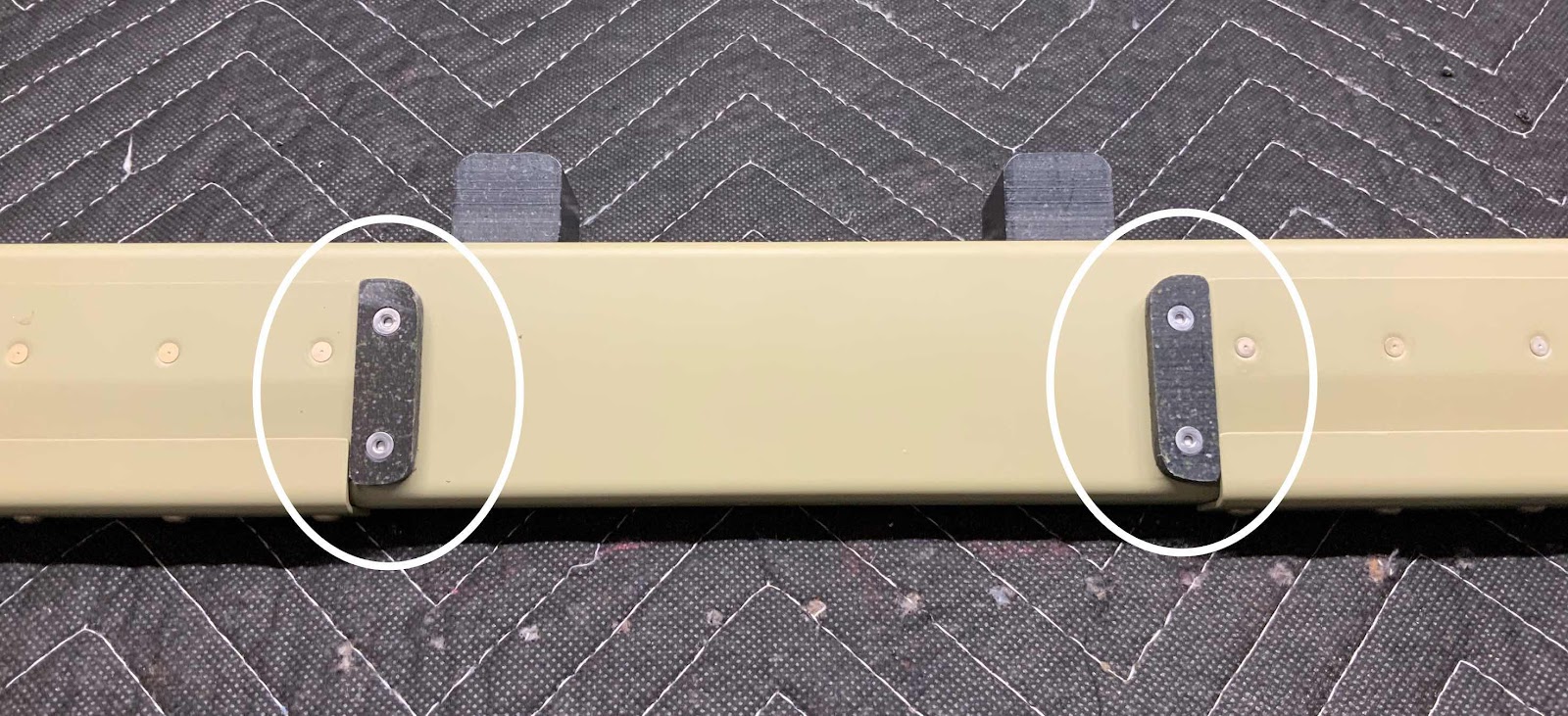
Next, the four F-01405N Seat Back Adjustment Guides previously fabricated are attached to the Brace. Each of the four Seat Back Guides were aligned with the forward edge of the F-01405K Guides (even with the top edge of Seat Back Guides in the picture below) and matched-drilled #30. The #30 holes matched-drilled in the Seat Back Guides were then countersunk to accept the heads the rivets attaching them to Brace. Each of the Seat Back Guides received two AACQ-4-4 Rivets. Here are the two “inside” Seat Back Guides attached the Brace.
 ``````
This is the whole Brace showing the four Seatback Gussetts and four Seat Back Adjustment Guides screwed and/or riveted into place.

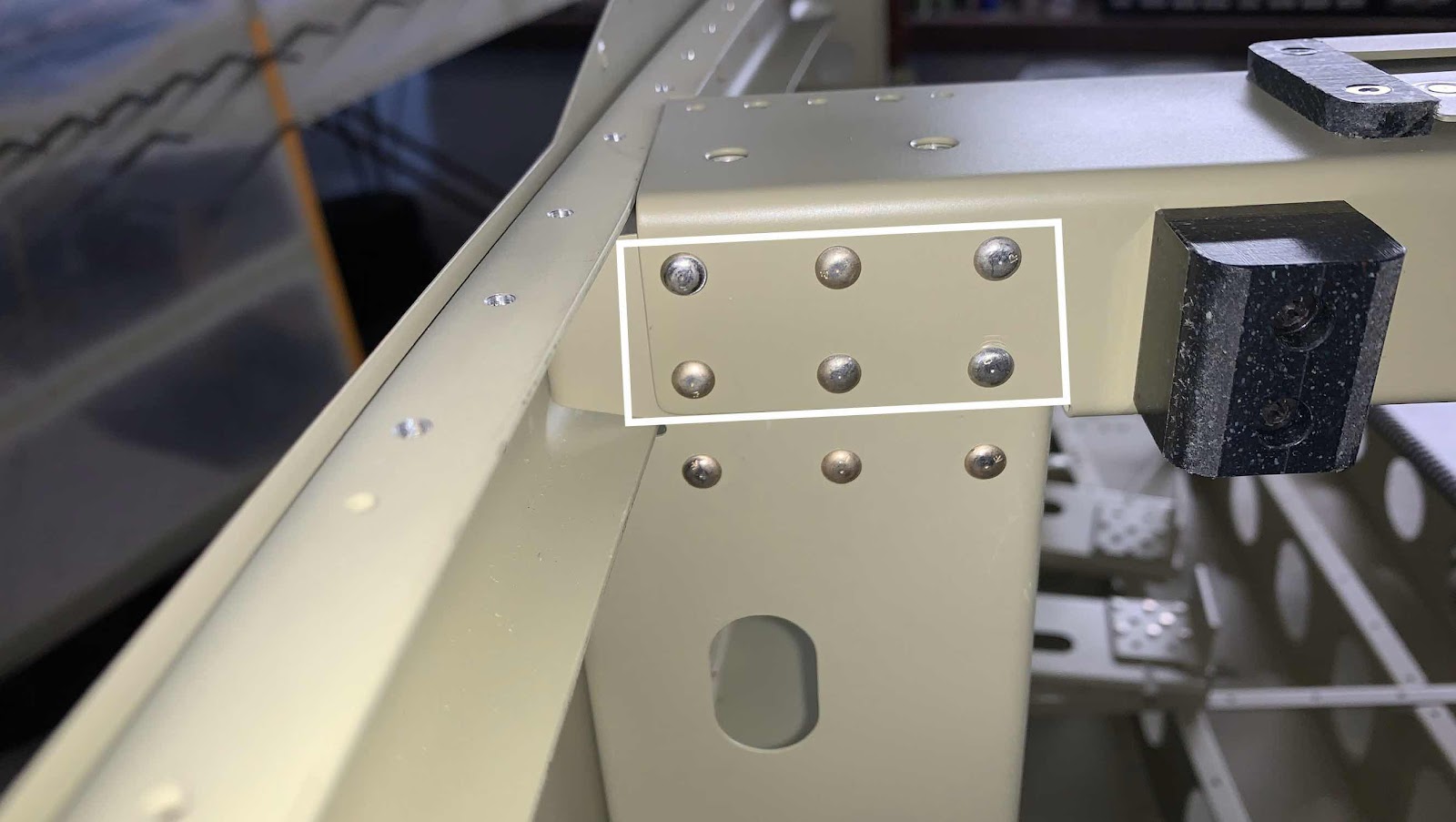
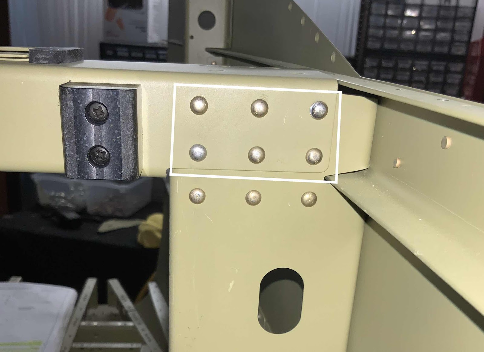
Once the Brace was completed, it was clecoed and riveted to the F-01405D-L &-R Bulkhead Side Channels. This is the right side of the plane showing the manufactured head side of the six AN470AD4-6 rivets installed in this step.....
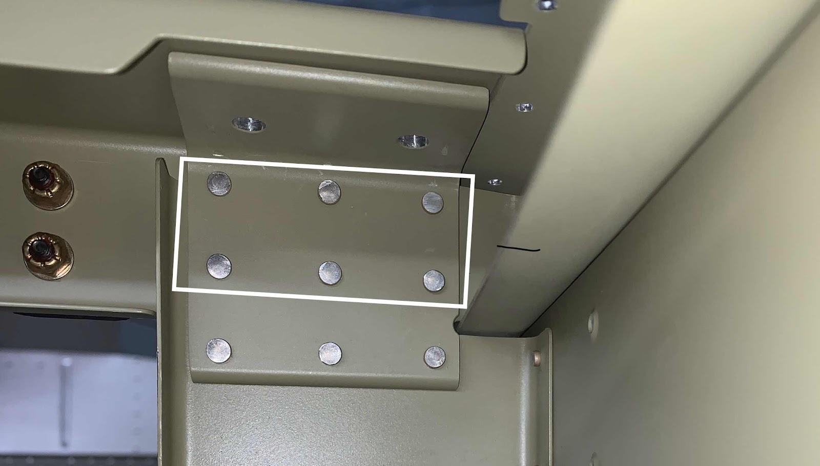
.....and the shop head side.
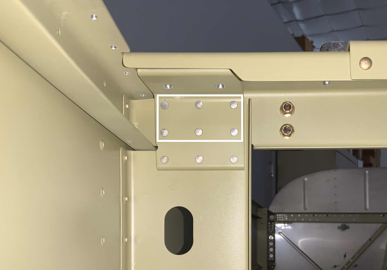
Here is the left side showing the manufactured heads of the six AN470AD4-6 rivets.....
Here is the left side showing the manufactured heads of the six AN470AD4-6 rivets.....
.....and the shop head side.
The next step was to cleco the Gussetts into place with the Upper Longerons and Brace as shown below (right side in the first picture, left side in the second) and temporarily install the two bolts (you can see the two bolt heads).
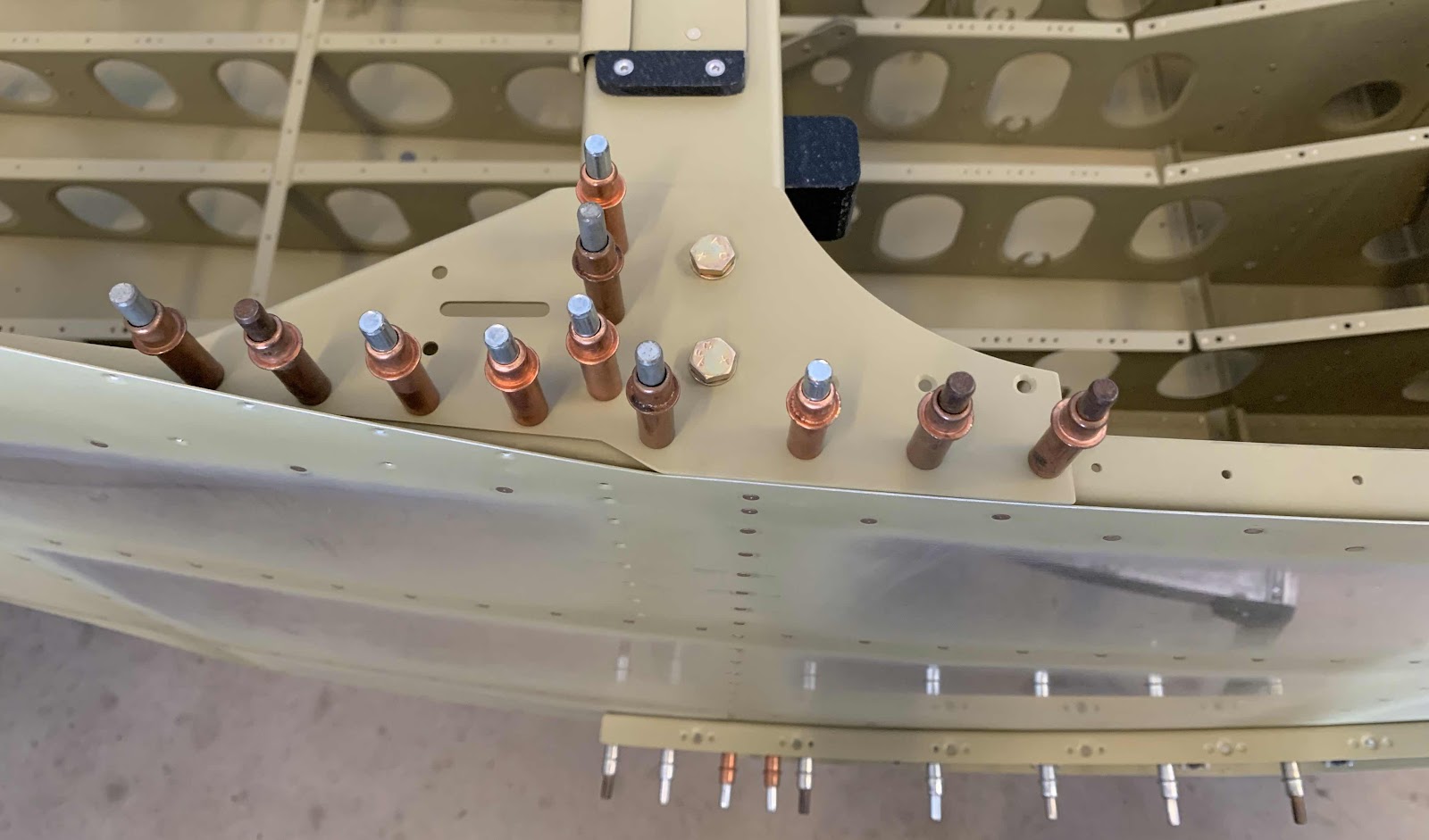

I started the riveting process for the Gussetts, but didn’t get very far. I will pick it up here during the next session.