This blog was created to memorialize the building process of my Van's Aircraft RV-14 and to satisfy the requirements for certification in the Experimental Amateur Built Aircraft category. It will also serve as a central location for ME to reference in the future on processes and techniques I used during the build. Additionally, it will allow my family, friends, and other interested builders the opportunity to follow along during my build…..and might be helpful to someone along the way.
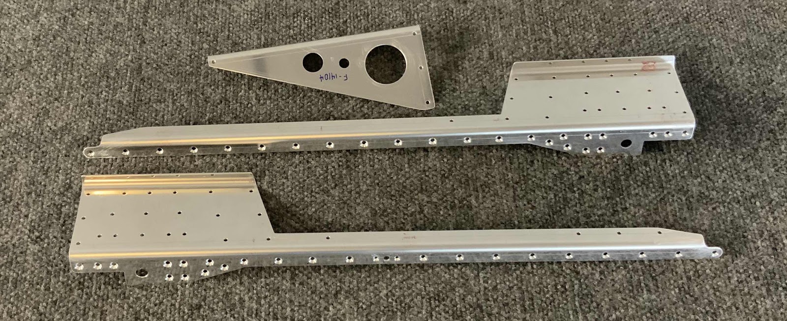
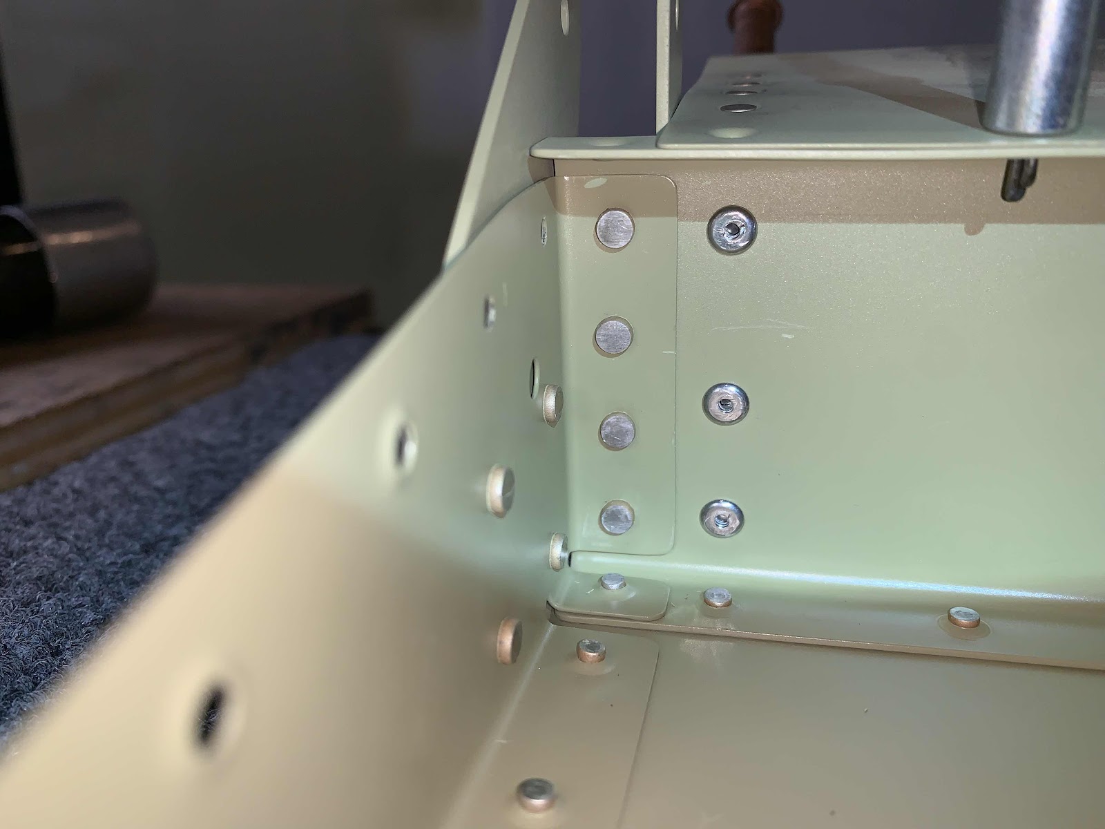
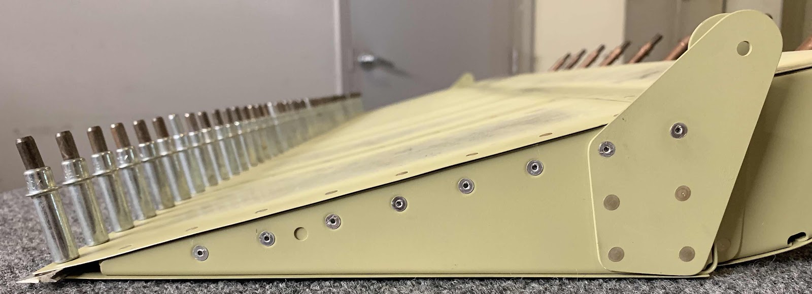
This section starts off with separating the F-01401E Firewall Angles. Once they were separated, the #40 holes (there were only two for the nutplate) and #30 holes were countersunk in the forward flange (you can see the countersunk holes in the picture below). The F-14104 Support Angle is also shown in the picture below. All three pieces had their edges cleaned, holes deburred and treated with Alumiprep and Alodine.....
....then they were primed.
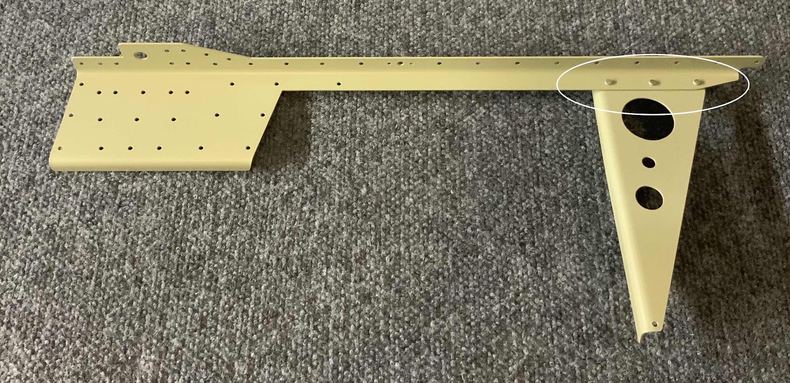
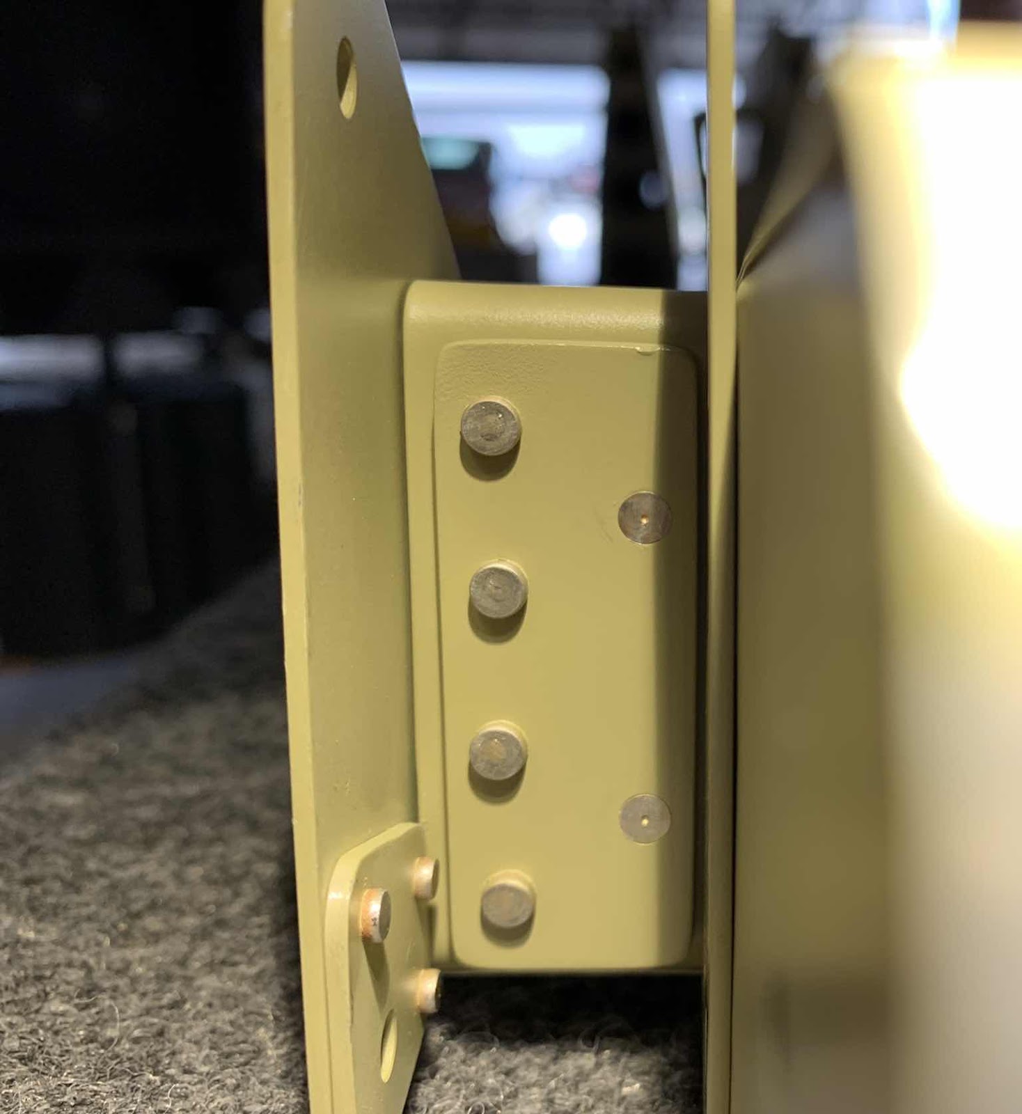
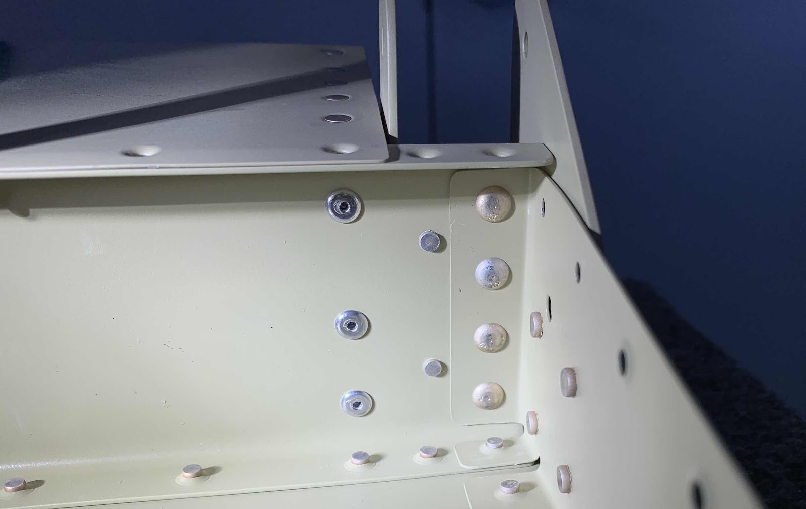
Once the primer dried, the Support Angle was riveted to the left Firewall Angle using three AN470AD4-5 rivets. This shows the shop head side.....
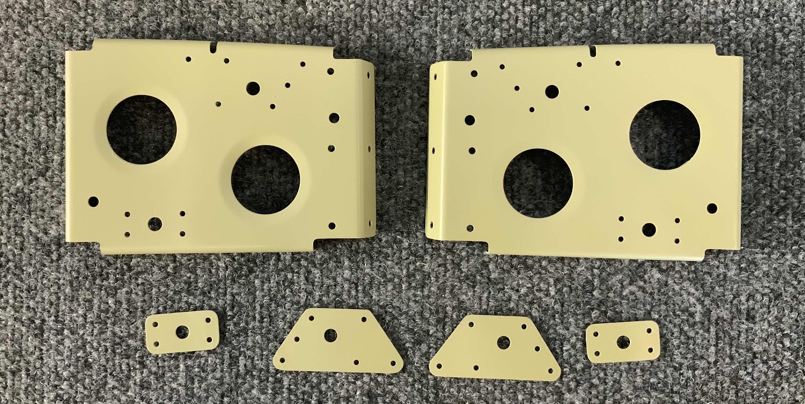
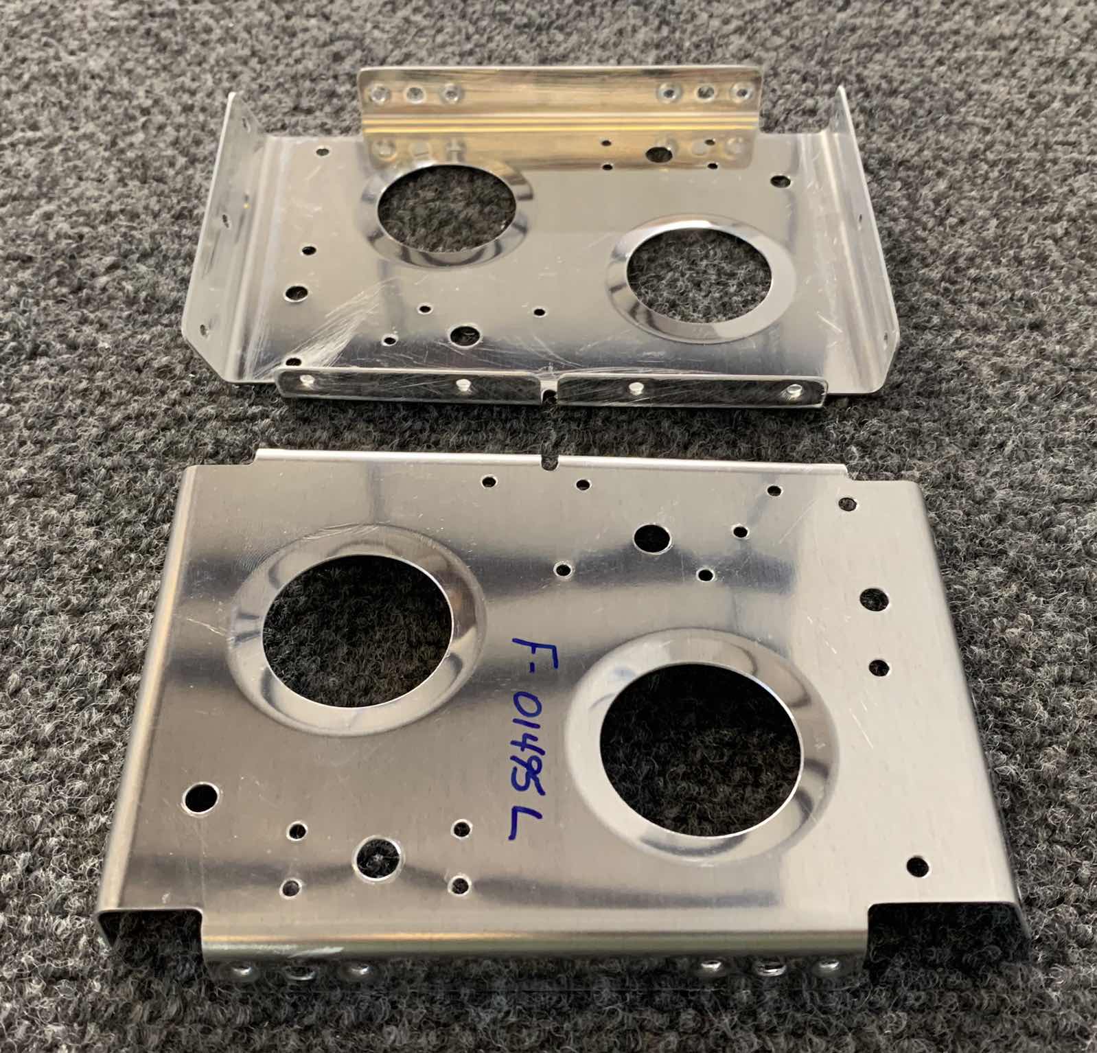
Yesterday, I treated several parts with Alumiprep and Alodine.....today, they get primed. These are the F-01458A-L & -R (small ones) and F-01458B-L & -R (large ones) Side Brackets.....
.....and the F-01458-L & -R Side Frames.
The two small Side Brackets were riveted to the Side Frames using AN470AD3-3. Here are both sides of the Frame after the Brackets were riveted into place.
The F-01430 Baggage Floor Stiffener was also primed.....
.....and received two K1000-08D nutplates with AN425AD3-3.5 rivets.
During the last session, I treated the Step Attach Rib Doublers and Step Attach Ribs with Alumiprep and Alodine. After allowing them to dry overnight, I sprayed them with Akzo primer this afternoon. Here are the six pieces after letting the primer dry.
I riveted the four Doublers to the Ribs as shown below. The four Doublers took 20 AN470AD3-3 rivets (10 on each Rib). The manufactured heads are shown on the left and the shop heads on the right. Each one of the Ribs also had two K1000-08D nutplates installed with two AN426AD3-3.5 rivets.
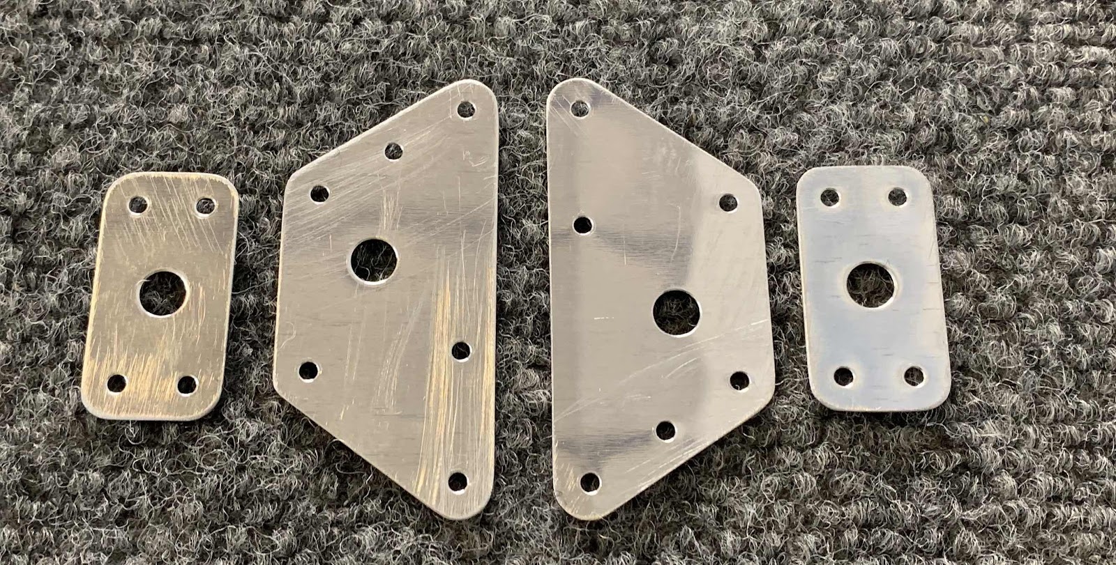
During this session, I also prepared the last few parts and pieces for this section. These pieces came in one connected piece from Van’s known as the F-01458AB Side Brackets. They were separated into F-01458A-L & -R (small ones) and F-01458B-L & -R (large ones). All the edges were cleaned, holes deburred and dimpled.
These are the F-01458-L & -R Side Frames. They have had their edges cleaned, holes deburred and dimpled.
The last piece in this section to be prepared was the F-01430 Baggage Floor Stiffener. The edges were cleaned, holes deburred and dimpled.
The seven pieces prepared today are ready to be treated with Alumiprep, Alodine and Akzo Primer. I will do this during the next work session.
Now that the Ailerons are finished, I switched back to the MID Fuselage Lower Structure. Not a very long work session, but I did prep several parts. These four parts started their life at Van’s known as F-01495AB Step Attach Rib Doubler. After being separated, the two bigger pieces became the F-01495A’s and the two smaller pieces became the F-01496B’s. All four pieces had their edges cleaned and holes deburred.
Here are the F-01495-L & -R Step Attach Ribs. These came as two pieces and didn’t have to be separated. All the edges were cleaned and holes deburred. Additionally, the #40 holes in the upper (nutplate locations) and lower flanges were dimpled.
After being prepared, all six pieces were treated with Alumiprep and Alodine and hung up to dry. Tomorrow, I will Akzo prime the parts and rivet them together.
Today I finished up the left and right Ailerons. The last step to complete both of them was to install/rivet the V-Channel to the trailing edges. To start, I cleaned the V-Channel and the inside trailing edges of the Skins with alcohol. Next, I applied the 3M adhesive tape to both side of the V-Channel, installed it between the Skins, slowly pulled the backing from the double sided adhesive, and installed clecos to hold the Skins and V-Channel in place.
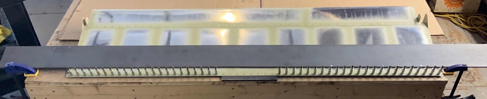
I started riveting from the center of the Skins and worked outward toward the ends. I also used my two steal plates to complete the riveting the same way I use them to complete the Flaps.
Here are the first eight rivets after being set.....
.....and a little closer.
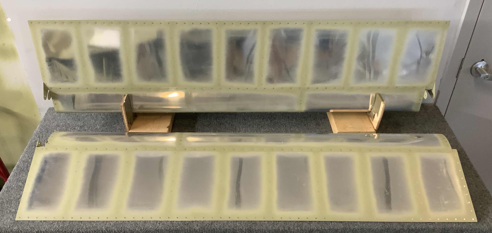
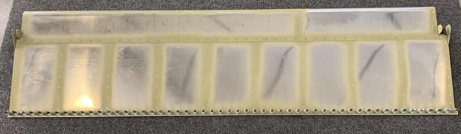
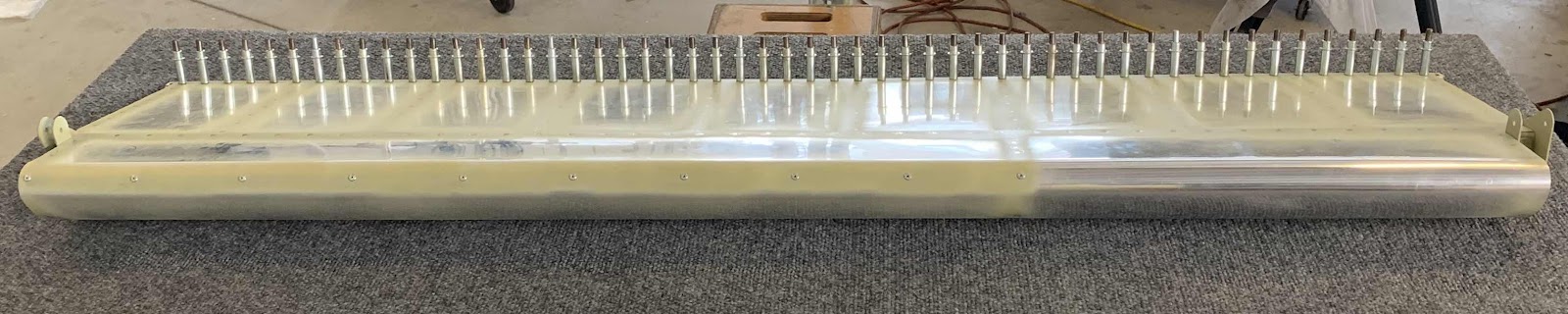
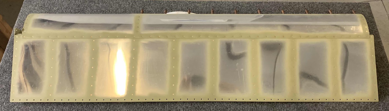
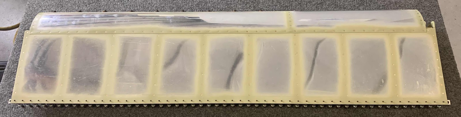
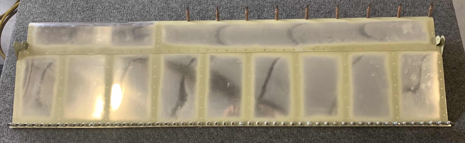
Here are the two completed Ailerons (left one in the cradle and the right one on the table).
During today’s sessions, the Bottom Skin for the right Aileron was riveted to the Spar. First off, the Bottom Skin was clecoed into place so I could check for any twist (just like I described for the left Aileron in Part 25). Once that was complete, the riveting could begin. Just as with the left Aileron, the plans have you first rivet every 10th hole in the Bottom Skin assembly and then randomly the remaining holes.....for a total of 43 holes/rivets. The plans call for AN426AD3-3.5 rivets, but they measured a little short.....AN426AD3-4’s measured perfectly. So, I decided to use the -4’s instead. Shown below is the completed right Aileron Bottom Skin.
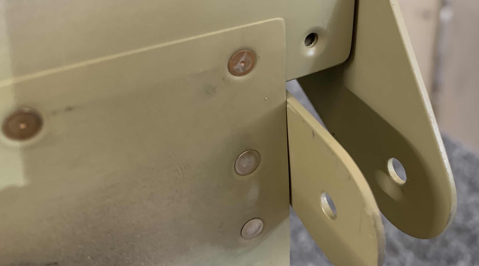
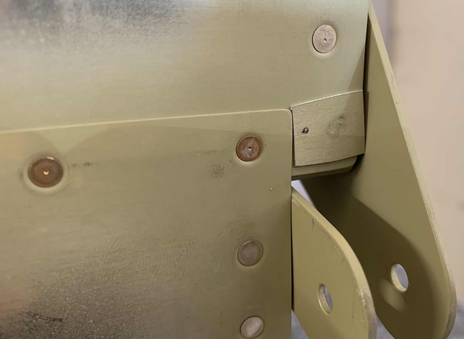
There was one hole in the assembly that was.....well, different. In the picture below you can see the hole I’m talking about. The hole itself is lower than the Nose Skin next to it and the Outboard Hinge Bracket will not let a standard 1” Mushroom Setor 3/4” Mushroom Setsit flush on the Bottom Skin and the rivet. So, I had to improvise.
I just happened to have an OLD Nose Skin laying around that I jacked up a few months ago, so I cut a piece of the Nose Skin that would fit in the area over the rivet.....and taped it into place. This made the two surfaces flat and allowed me to use the 1” mushroom set to set the rivet.
Here is what the rivet looked like after being set.
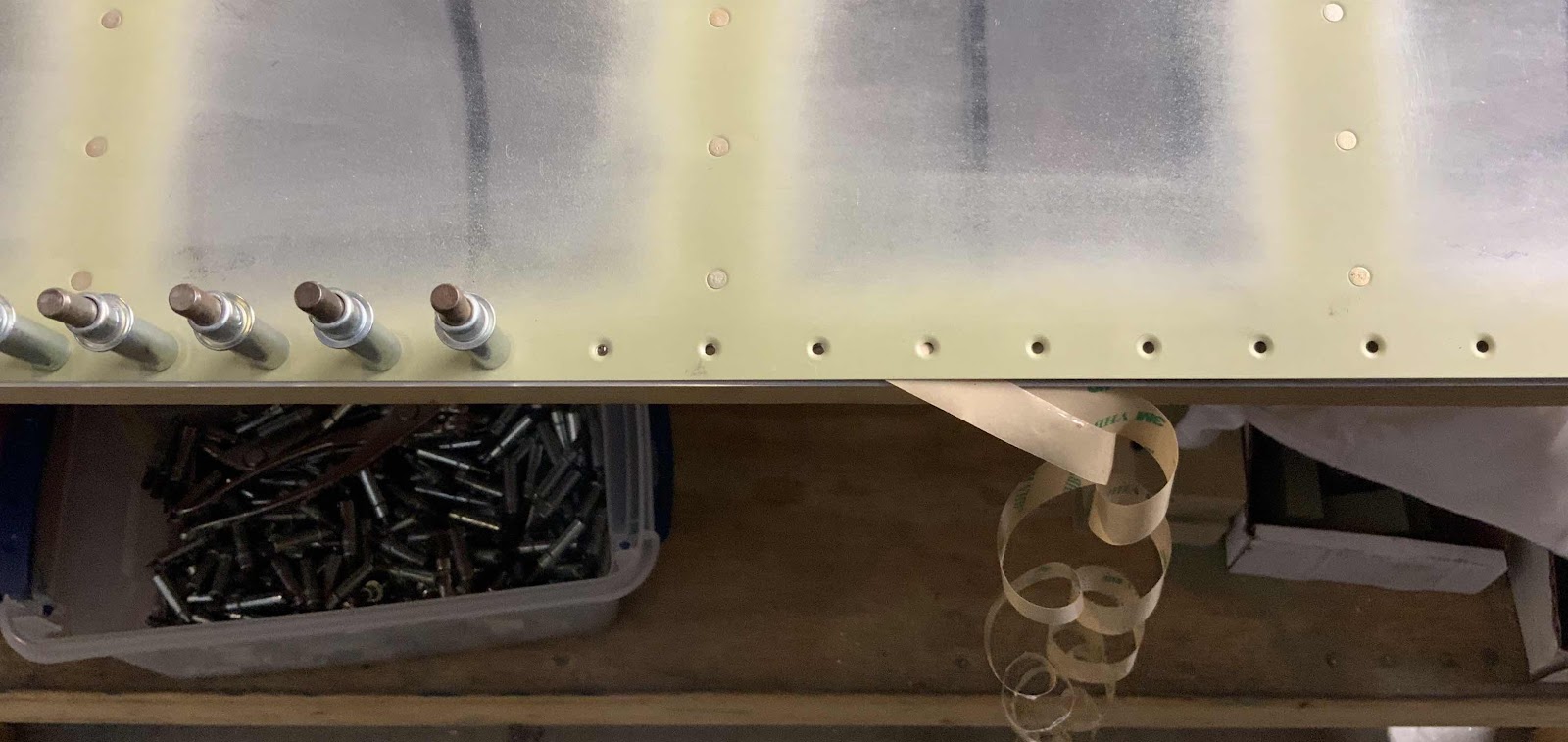
After the Bottom Skin was riveted to the Spar, the next step was to install the 20 (10 on each Aileron) LP4-3 Blind Rivets in the Nose Skin and Counterbalance. You have to look closely, but you can see the rivets in the leading edge:
After letting the Akzo primer dry from the previous session, I started the final Aileron(s) assembly process in this session by riveting the A-1008-1 Doublers the left and right Spar. The only rivets that get set during this step are the four AN426AD3-5 on the inboard side of the Doublers. I used the pneumatic squeezer to set these four. The other four holes in the Doublers will be used to attach the Ribs to the Spar (in a later step).
Because the left and right Aileron’s were completely disassembled, I took the time to final install the hardware connecting the Counterbalance to the two A-1004-1R & -L Nose Ribs. The hardware for this installation is in the square box at the bottom of the picture below. I used LPS3 to generously coat the screws, nuts, Ribs, and Counterbalance.
—————————————————————————————————————
Saturday, June 8, 2019
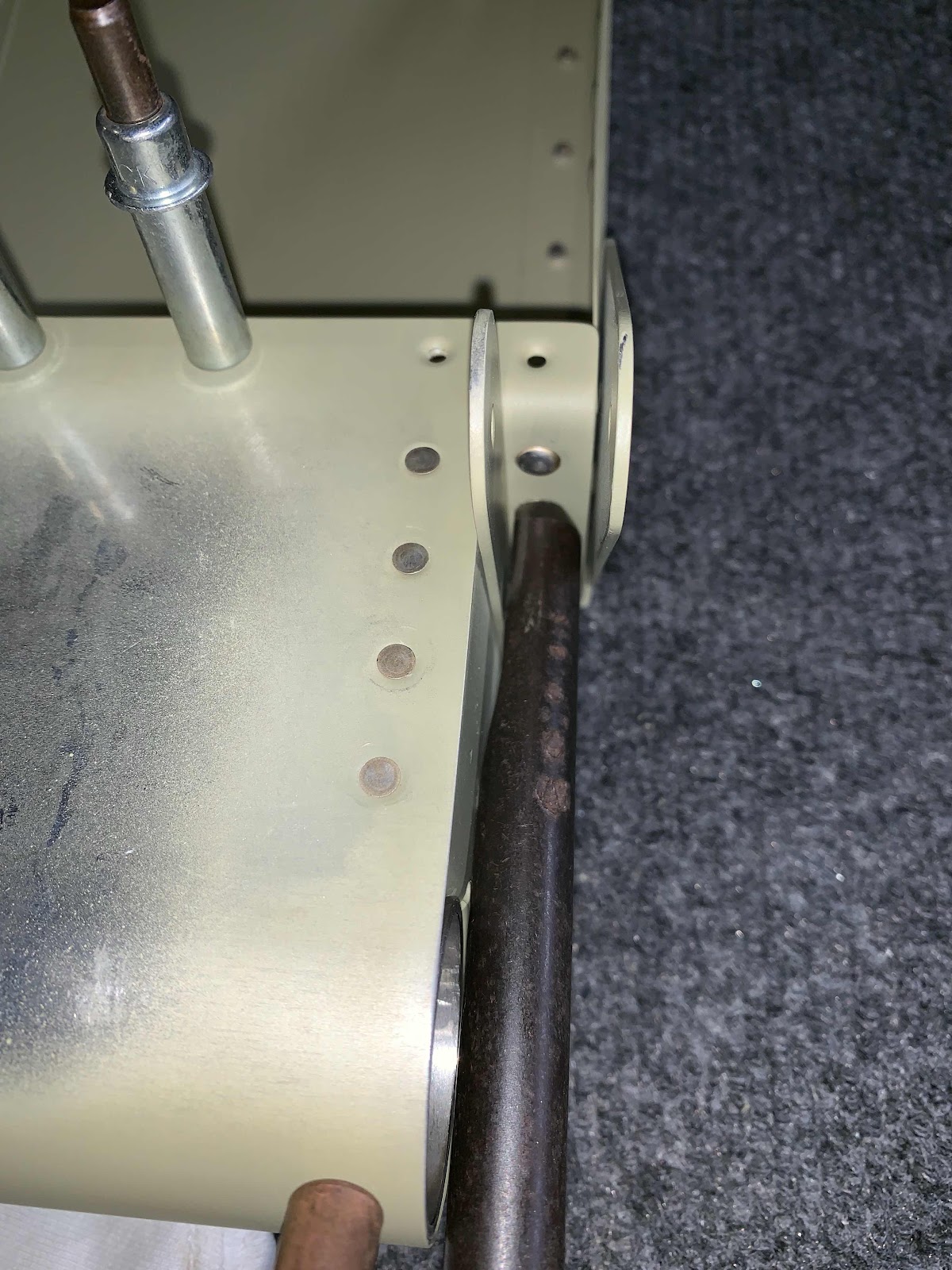
I started off today by setting the eight (four in each Aileron) AN470AD4-4 rivets in the Main Ribs to Spar. Pictured below is the right Aileron and the manufactured head of the rivets (already set). Now, the “rule of thumb” is to put the manufactured head of the rivet on the thinnest material. The flanges of the Main Ribs are definitely the thinnest material, but will NOT get the manufactured head of the rivet. The reason is the space between the Brackets is not wide enough to get a bucking bar or the yoke from a pneumatic or hand squeezer in there to set the rivets. Additionally, there is a slant between the Spar and the Top Skin that would prevent getting a rivet gun set squarely on the rivet (can’t really make it out in the picture).
Here is the shop head side of the four rivets shown above. The left Aileron was completed the same way. How did I do this?
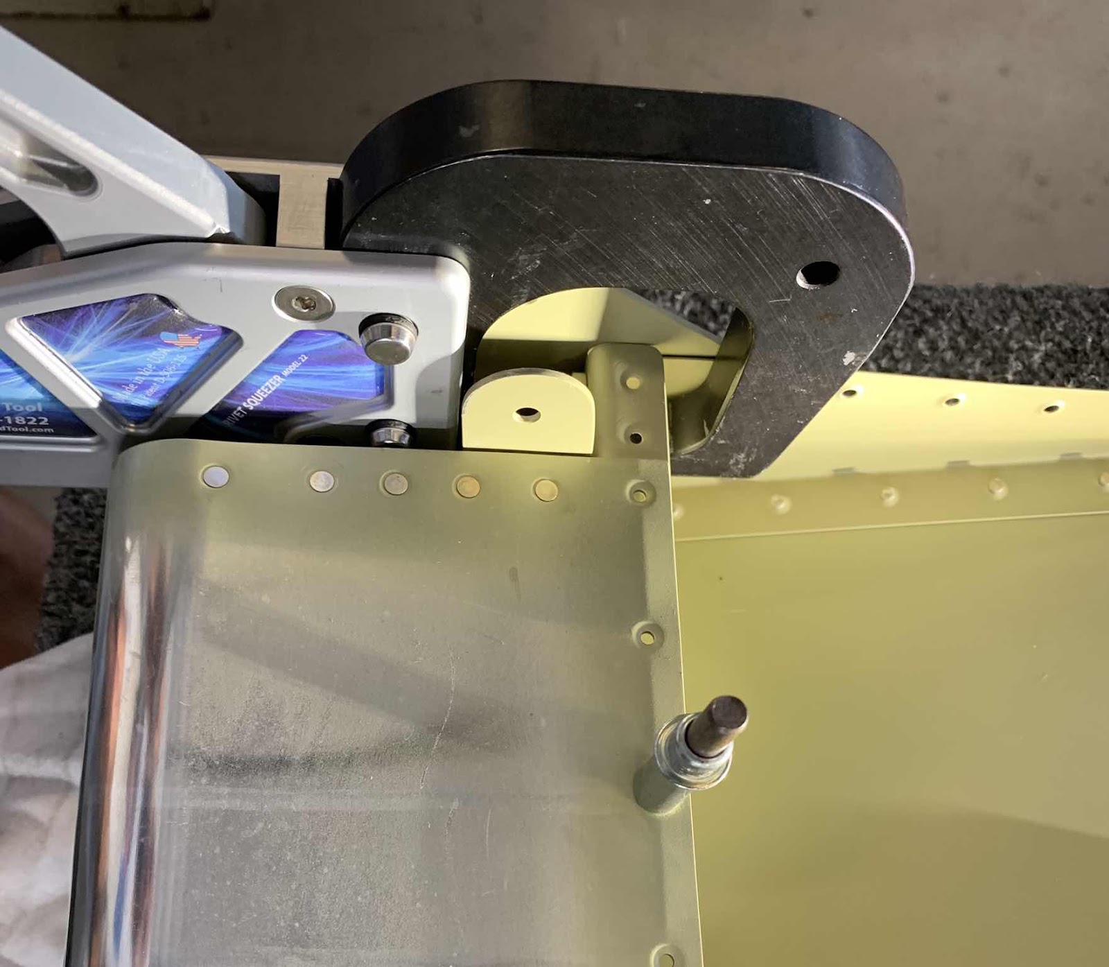
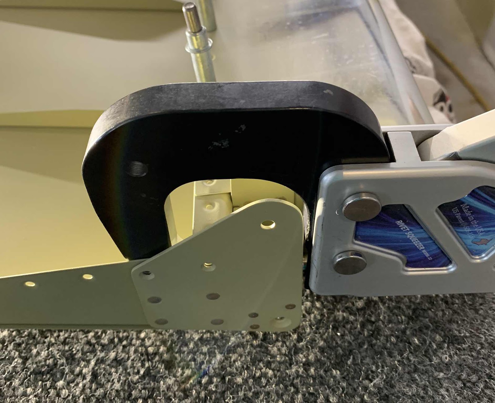
The space between the Brackets I mentioned above was also too narrow to get an “un-modified” rivet set between them. I had a
This made the Set skinny enough to fit between the Brackets. Here are a couple of pictures of what it looked like.
Holding the bucking bar on the opposite side was very easy and produced the results I showed in the pictures above. Next, was to cleco the Top Skin to the Spar at every other hole and clamp a straight board to the Top Skin assembly near the trailing edge (to hold the Top Skin straight while riveting). I didn’t have a board that I thought was sufficient, but I did have a Rear Spar I previously jacked up on the Elevators. So, I used the old Spar and clamped it to the Top Skin as shown below.
I started today’s session by checking the right Aileron Nose Skin for “bowing”. I found only minor bowing, if any, by following the directions in the plans (see Part 16 for this process on the left Aileron Nose Skin).
Once that was completed, I treated the two Aileron Nose Skins with Alumiprep and Alodine. After both Nose Skins were completely dry, I Akzo primed both Nose Skins and both Spars. I will let them dry and start the assembly process during the next session.
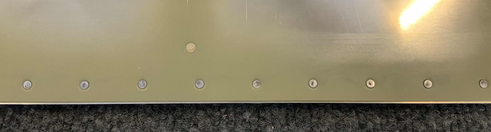
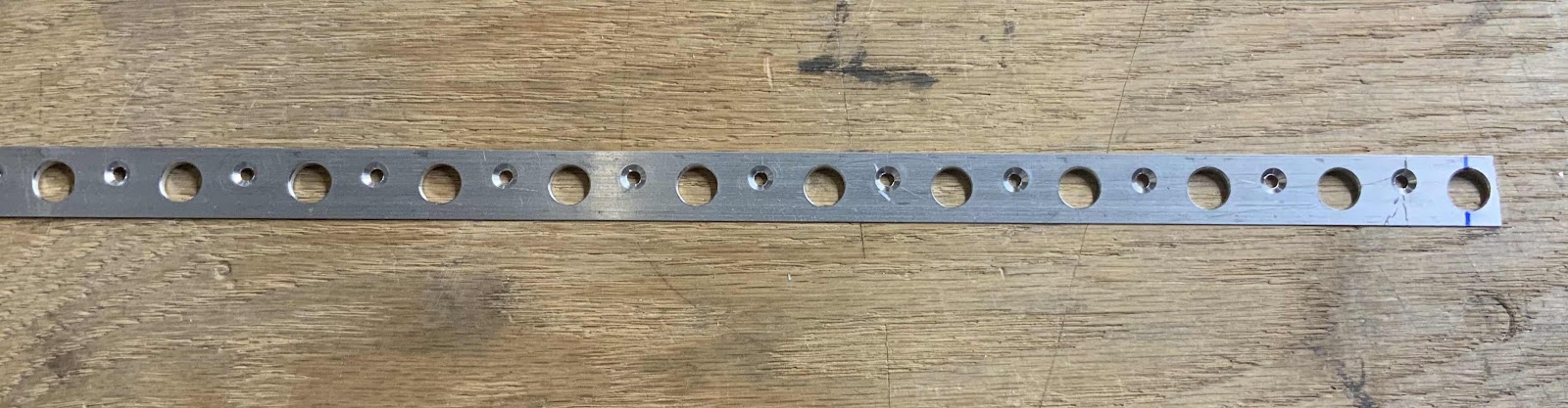
During yesterday’s session, I clecoed together the whole Right Aileron. The first step today was to verify there was no “bowing” in the Nose Skin. I did this the same way as I did for the Left Aileron (detailed in Part 16). There was a tiny little bit of “bowing”, but was easy to fix (the plans tell you how). The plans state as much as a 1/16th” of “bowing” is acceptable. Once I made the adjustments, there doesn’t appear to be any “bowing” on the Right Aileron Nose Skin. Once that was completed, I clecoed the V-Channel (shown below) to the aft ends of the Top and Bottom Skins and final-drilled all the holes #40. Lastly, I removed the V-Channel and countersunk each of the holes (both sides) to fit a dimpled #40 Skin. Here is a section of the completed V-Channel.
Once the V-Channel was taken care of, both Ailerons were completely disassembled. Below is the parts that make up the Left Aileron (minus the Spar and Nose Skin).....
.....and the Right Aileron (minus the Nose Skin).
After both Ailerons were disassembled, the left and right Nose Skins and Left Spar were treated with Alumiprep and Alodine. Not the best picture, but the three parts are shown hanging up to dry.
Tomorrow, these three pieces will get Akzo primed, the left and right Ailerons will get reassembled, and the riveting process will begin.