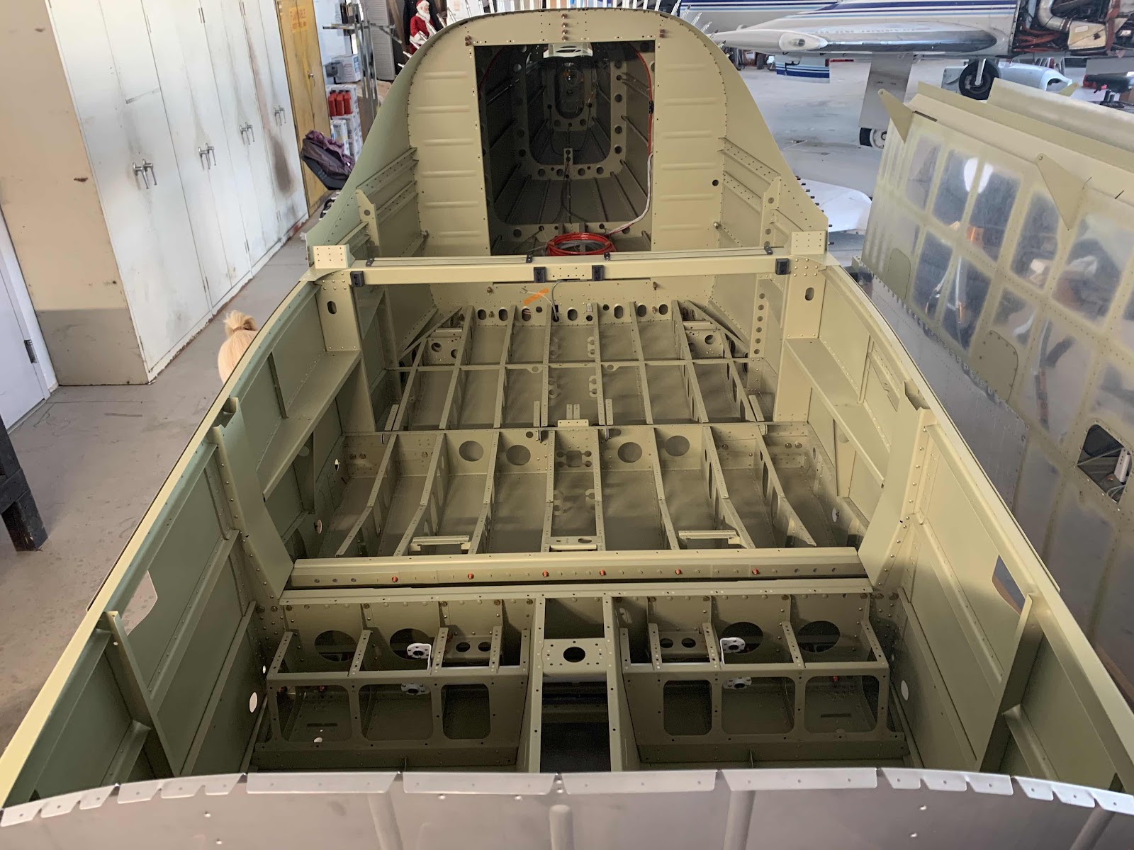
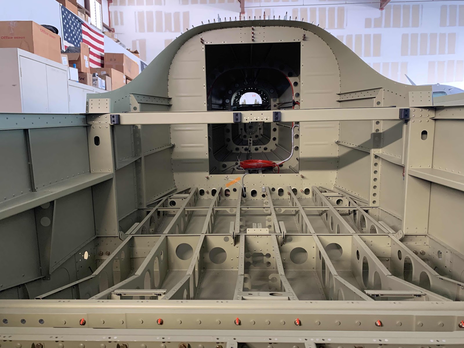
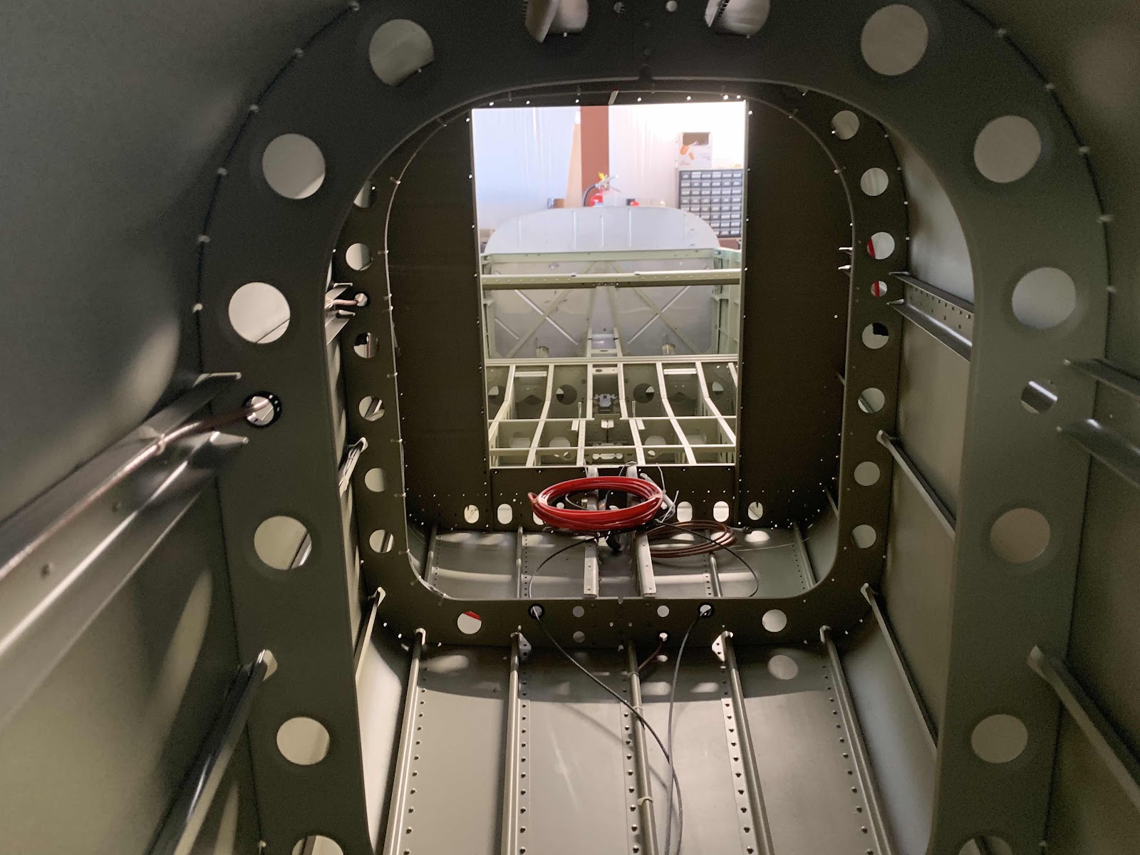
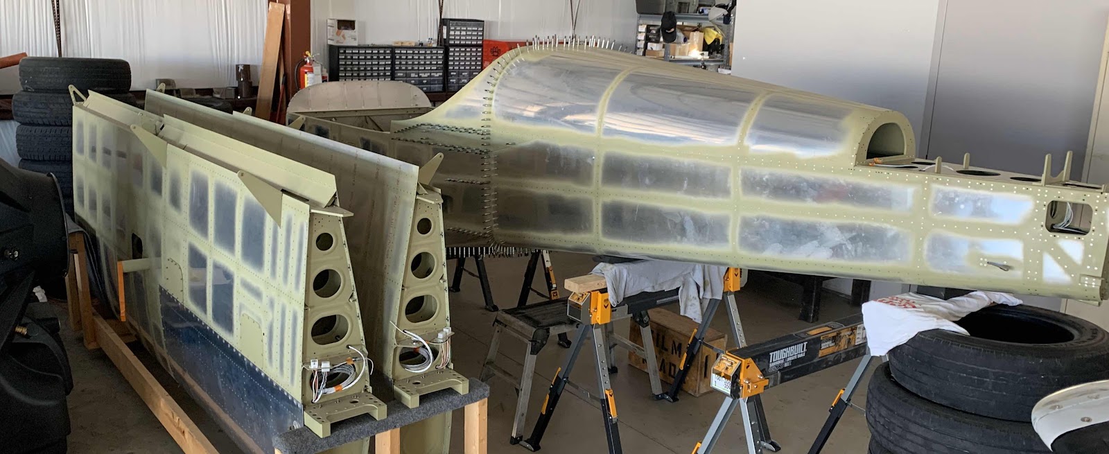
This blog was created to memorialize the building process of my Van's Aircraft RV-14 and to satisfy the requirements for certification in the Experimental Amateur Built Aircraft category. It will also serve as a central location for ME to reference in the future on processes and techniques I used during the build. Additionally, it will allow my family, friends, and other interested builders the opportunity to follow along during my build…..and might be helpful to someone along the way.
I meant to publish this entry the other day, but forgot. After joining the forward and rear halves of the Fuselage and preparing the Shoulder Harness Lugs and Clips, the next step is to start installing rivets. I want to wait until I have some help to get started with that portion of the section.
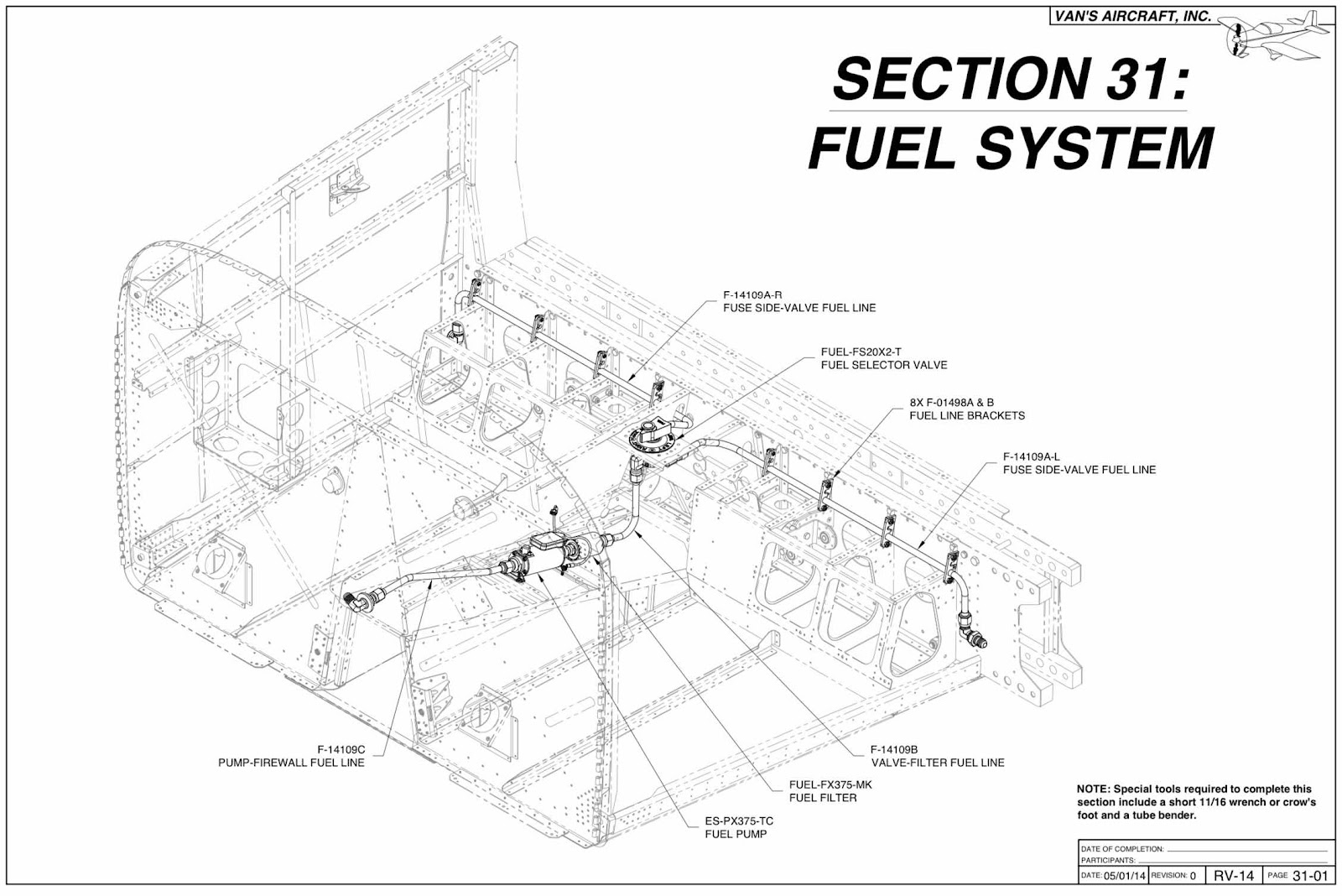
So, I decided to skip to the next section.....Section 31: Fuel System. I plan on purchasing an RV-14 Cabin Fuel Line Kit from Aircraft Specialty LLC, so I will wait for the fuel line package to arrive before I start the Fuel System section.
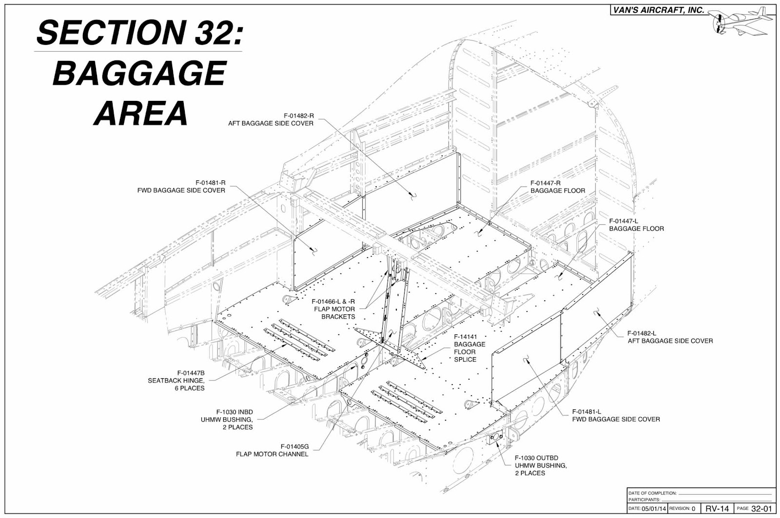
SO, I will also skip to the next section....Section 32: Baggage Area
As I mentioned, I’m waiting for some riveting help to finish the Aft Fuselage Attachment (Section 30) and I’m waiting for the RV-14 Cabin Fuel Line Kit from Aircraft Specialty to work on the Fuel System (Section 31). So, in the meantime, I will start work on the Baggage Area.
To start the section, six F-01447B Seatback Hinges had to be fabricated from AN257-P3 Piano Hinge. The plans excerpt below shows the dimensions of each of the six Hinges.
Here are the six Hinges fabricated from the AN257-P3. Each one of the Hinges has a #30 locating hole drilled in each end and a blue centerline marked lengthwise.
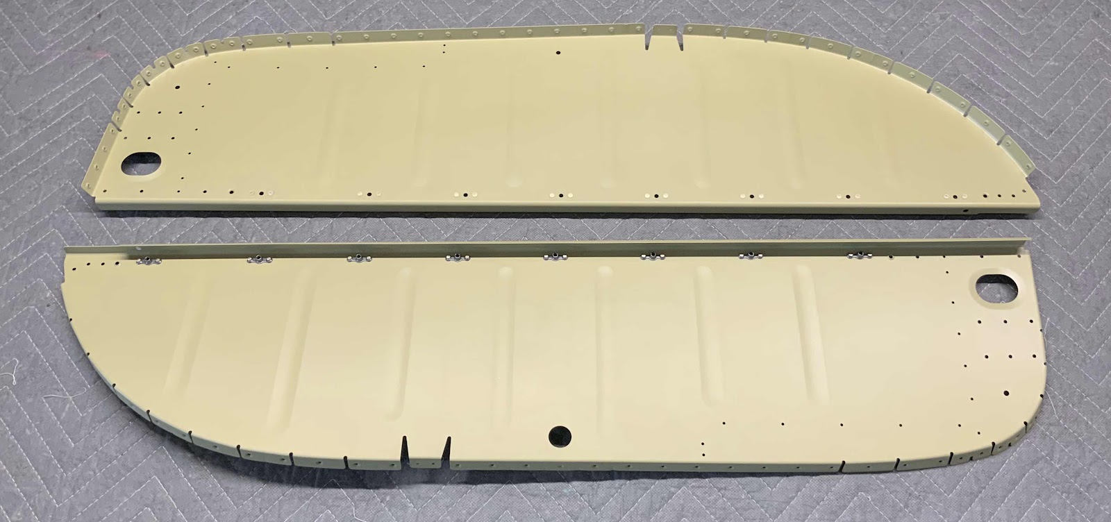
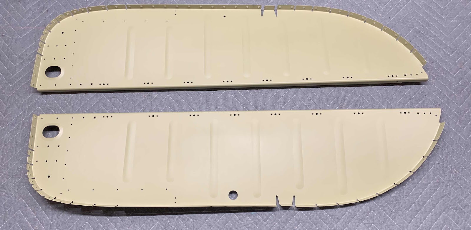
Three of the Seatback Hinges were clecoed to the F-01447-L Baggage Floor and three of the Seatback Hinges were clecoed to the F-01447-R Baggage Floor using the previously drilled locating holes. The blue centerline drawn on the six Hinges were centered in the prepunched holes in the Baggage Floor and match-drilled #30. Pictured below is the three Hinges match-drilled to the right side Baggage Floor.
Once all six Hinges were completed, they were marked, removed and had the holes deburred. They will now be set aside for use later in the build.
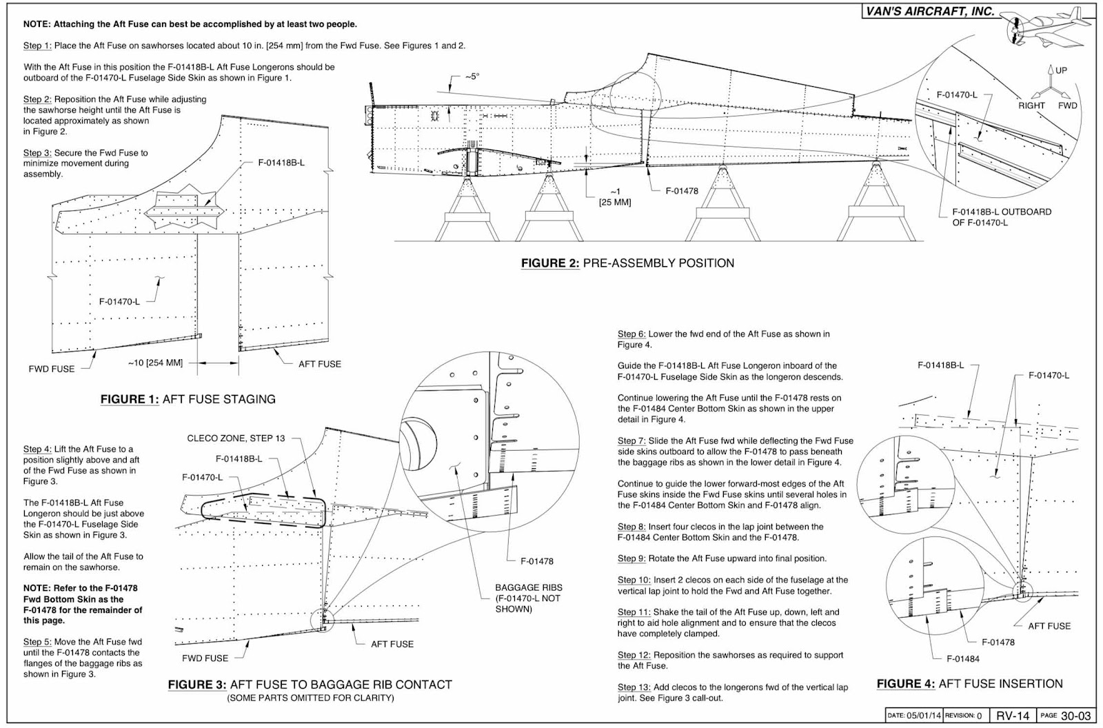
The forward and aft halves of the Fuselage get attached!!! The plans (shown below) goes through a very detailed process of attaching the two halves together. At first read, it was a little confusing and hard to follow. Then, I calmed down and read each step word for word.....and completed each step in order. Some advice.....have plenty of helping hands. We had a total of four people helping during this session and it made it so much easier. From moving the Fuselage halves around, adjusting the height of the sawhorses, to installing clecos.....more hands was a tremendous help.
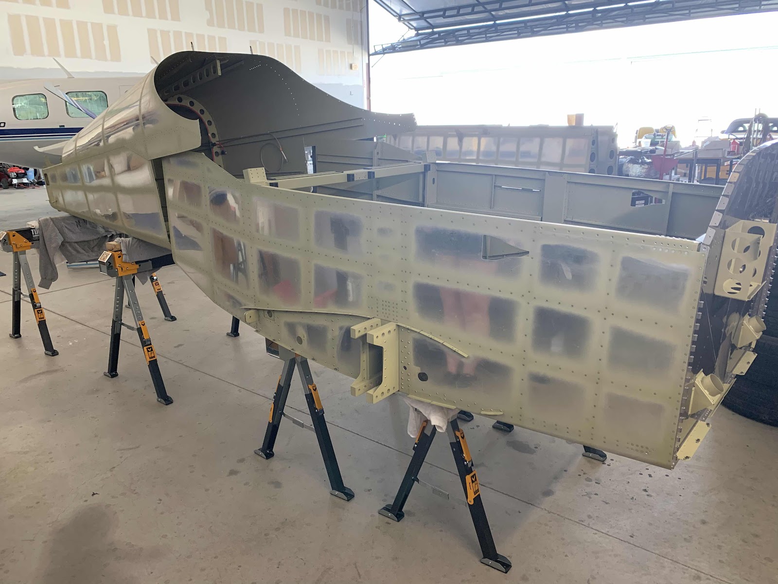
The plans describe using sawhorses to support the Fuselage halves while they are being joined. I like the idea of sawhorses, so I purchases these sawhorses from The Home Depot. They were a little expensive and probably overkill, but if the completed fuselage will need to be supported for several months, I wanted something solid. There were several other sawhorses available to choose from, but many were made of plastic and/or not adjustable. In the pictures below, you can see how the sawhorses were used for the Fuselage assembly. The first four pictures show the two halves positioned as described in the plans. The right side.....
.....the left side.....
.....looking aft toward the tail from the forward side of the baggage area.....
.....and from the Firweall.
Installing the FIRST two clecos it the bottom Skins.
We lifted the tail as described in the plans and made sure all the pieces (Skins, Ribs, Longerons, etc) fit where they were supposed to fit. Once it we were satisfied the fit was good, four more clecos were installed into the assembly (two on each side). Here are the two clecos installed on the right side of the Fuselage.....
.....and the left side of the Fuselage.
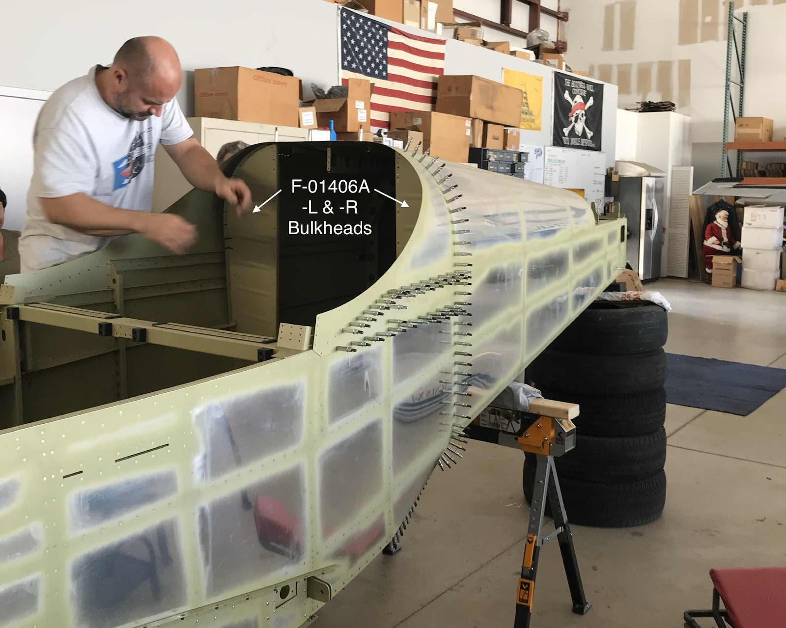
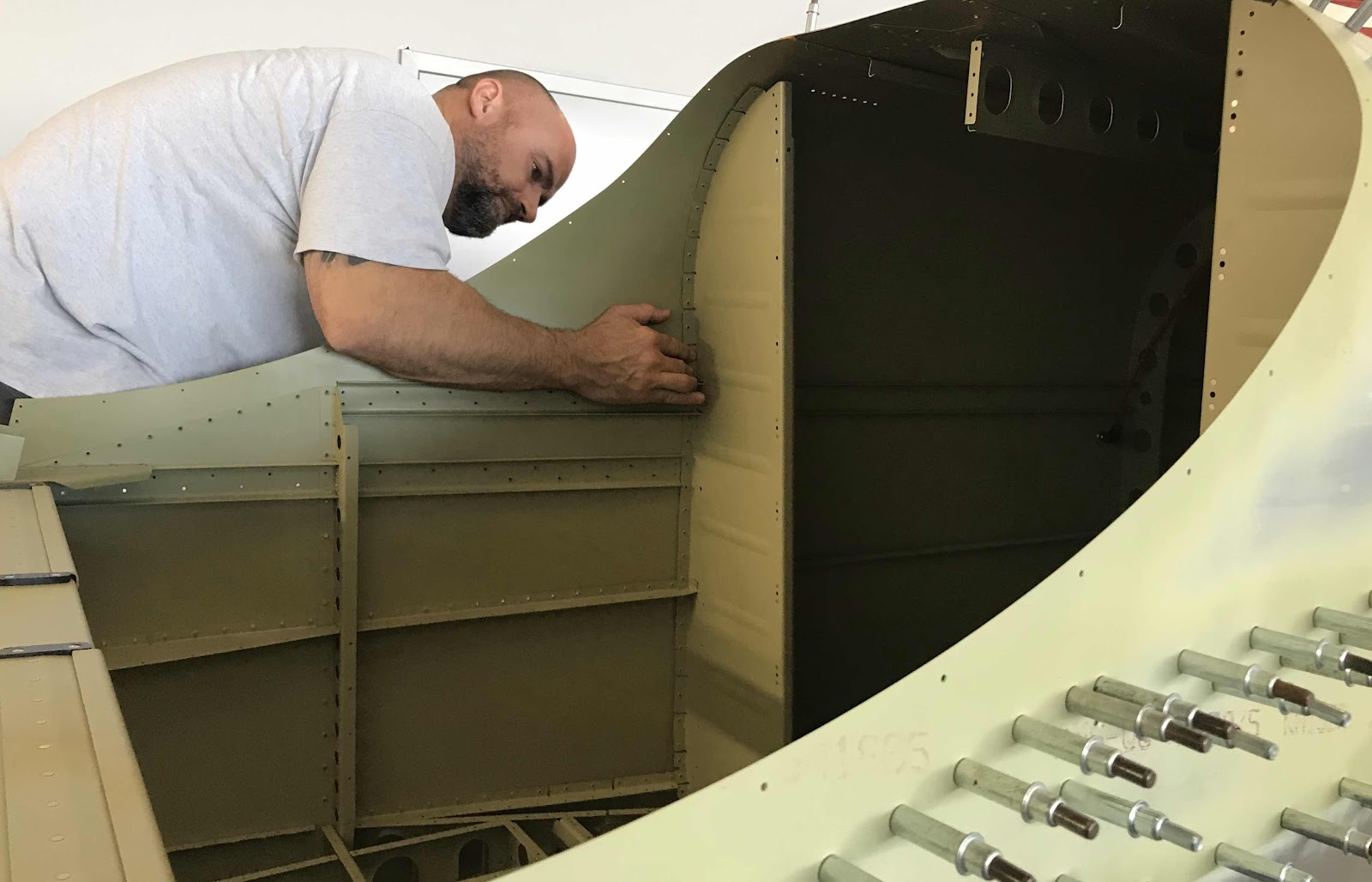
Once the initial clecos were installed in the assembly, the F-01406A-L & -R Bulkheads were put into place. In the picture below, the -L Bulkhead has already been clecoed into place....now, I’m working on the -R Bulkhead.
Still fitting the -R Bulkhead into its proper position.
Here are a couple pictures showing the two halves completely clecoed together.....ready for the rivets to be installed.
After all the clecoes were installed on both sides, the cradled Wings were rolled next to the Fuselage. Waiting for the next work session.
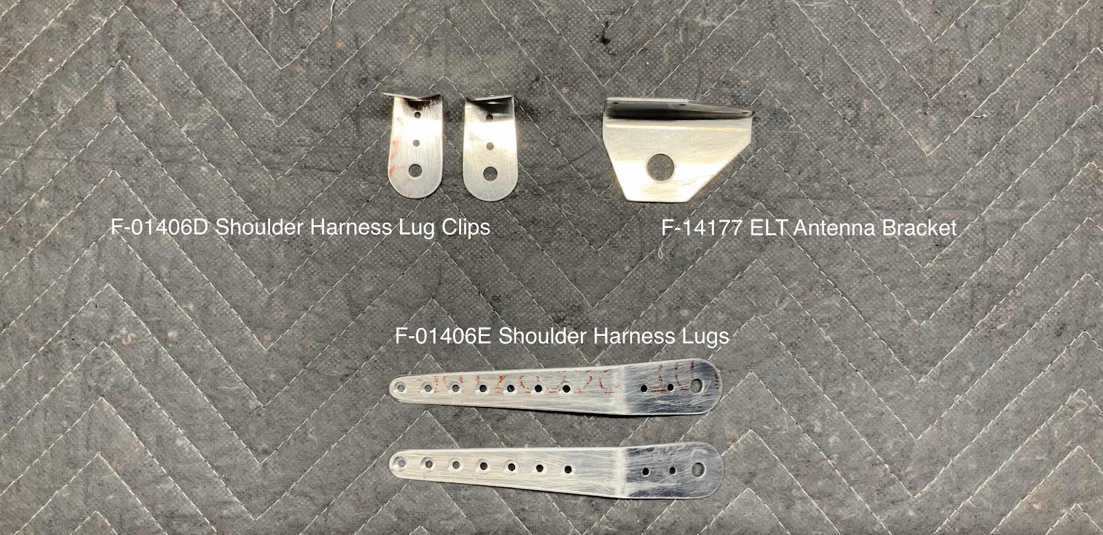
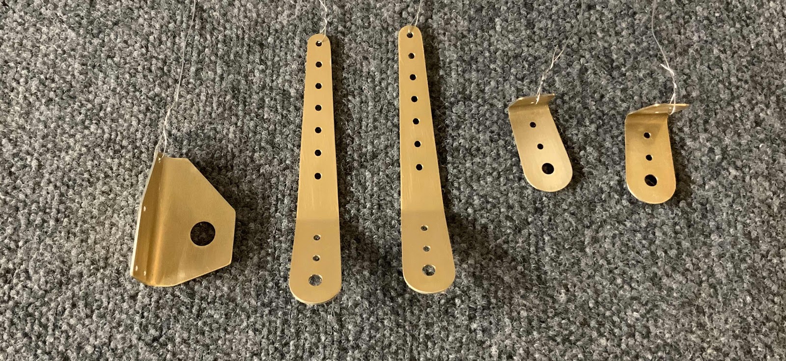
After joining the two halves of the Fuselage, the next parts to get prepared were the F-01406D Shoulder Harness Lug Clips, F-10406E Shoulder Harness Lugs and F-14177 ELT Antenna Bracket. The Lugs and Lug Clips were one piece and had to be separated, but the ELT Bracket was just one piece. After being separated, the edges were cleaned, holes deburred.....
.....and treated with Alumiprep and Alodine. I will Akzo prime the pieces during one of the upcoming sessions.
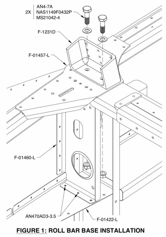
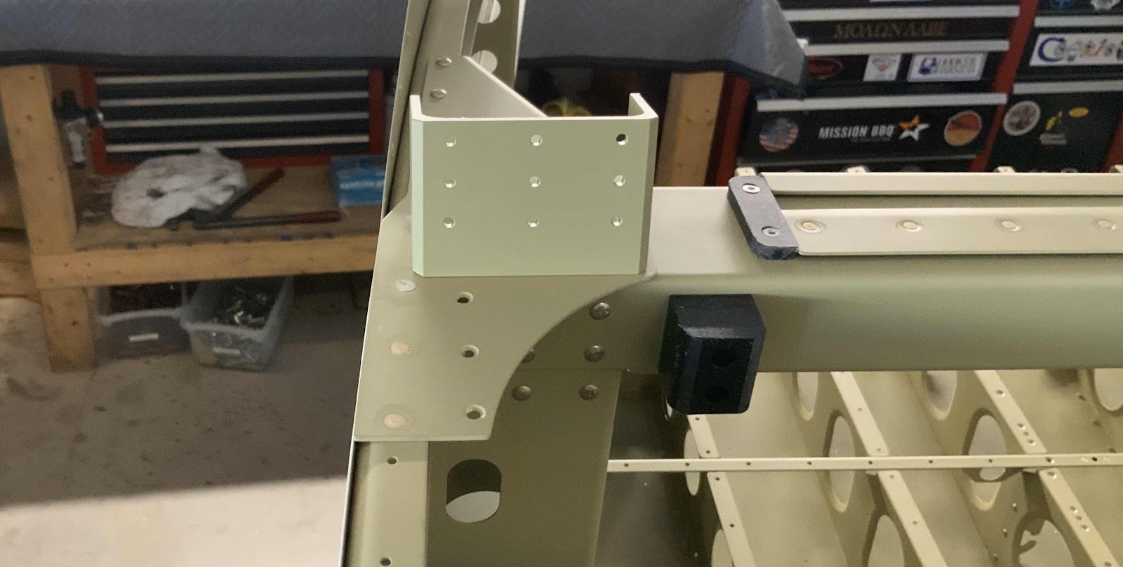
During the last session, the F-01460-L & -R Intercostals were riveted in place with the left and right Side Skins. Now, it’s time to bolt the F-1231D Roll Bar Bases for the final time. Here is an excerpt from the plans showing the hardware used.
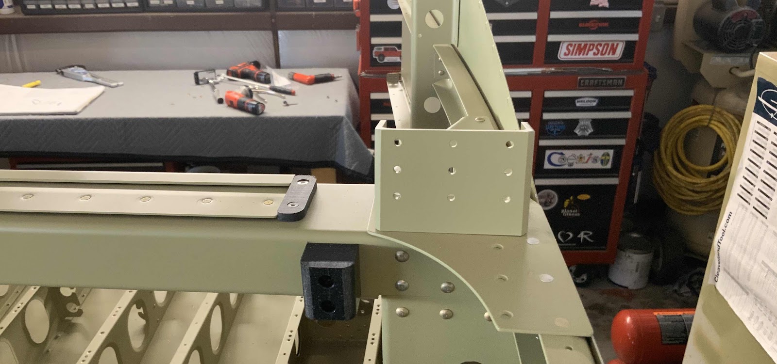
This is the forward view of the installed Roll Bar Base on the left side of the plane.....
.....and the aft side. You can see the heads of the AN4-7A bolts used for the installation.
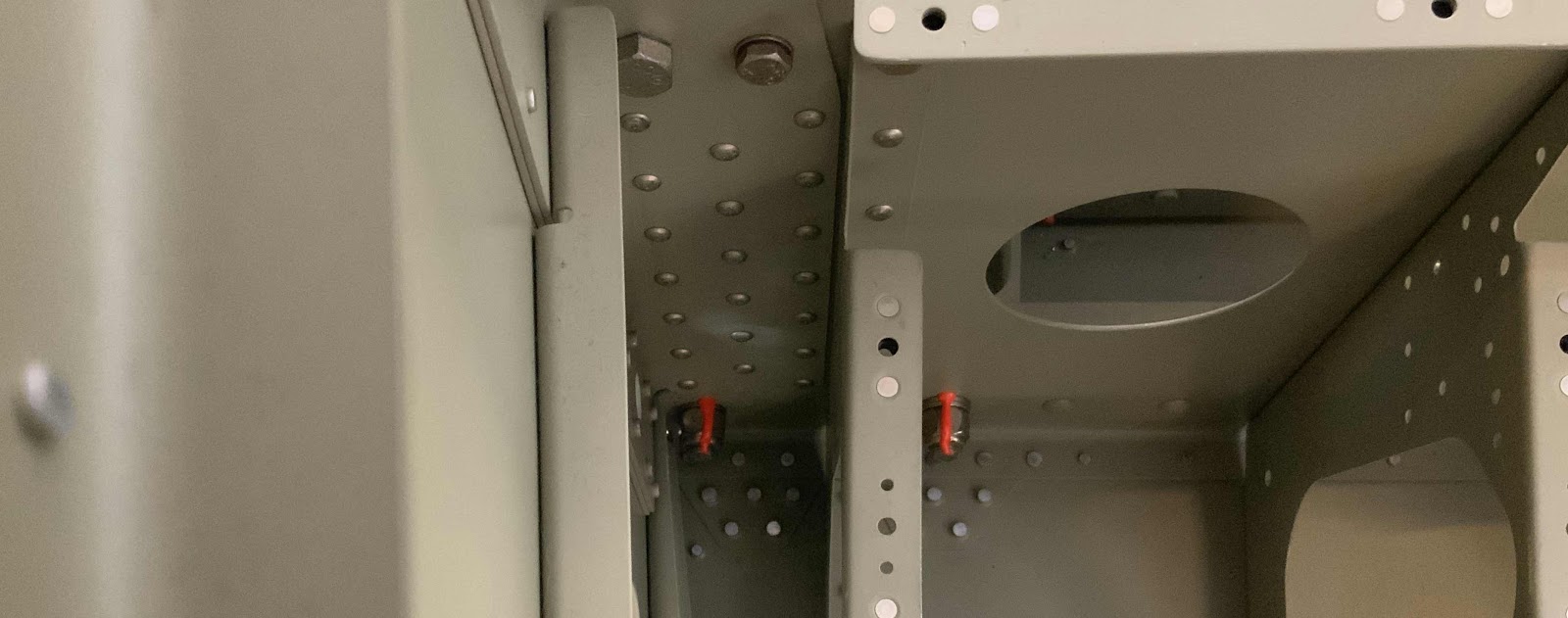
This is the under side of the left assembly showing the installed MS21042-4 nuts. I got a little excited with the torque seal.
The last step on the left side was to install the two AN470AD3-3.5 rivets in the bottom of the Intercostals to the Fuselage Side Ribs.
This is the forward view of the installed Roll Bar Base on the right side of the airplane.....
.....and the aft side. You can also see the heads of the installed AN4-7A bolts used for the installation.
This is the underside of the right assembly showing the installed MS21042-4 nuts. Again, a little excited with torque seal.
Finally, the last step on the right side was to install the two AN470AD3-3.5 rivets in the bottom of the Intercostals to the Fuselage Side Ribs.
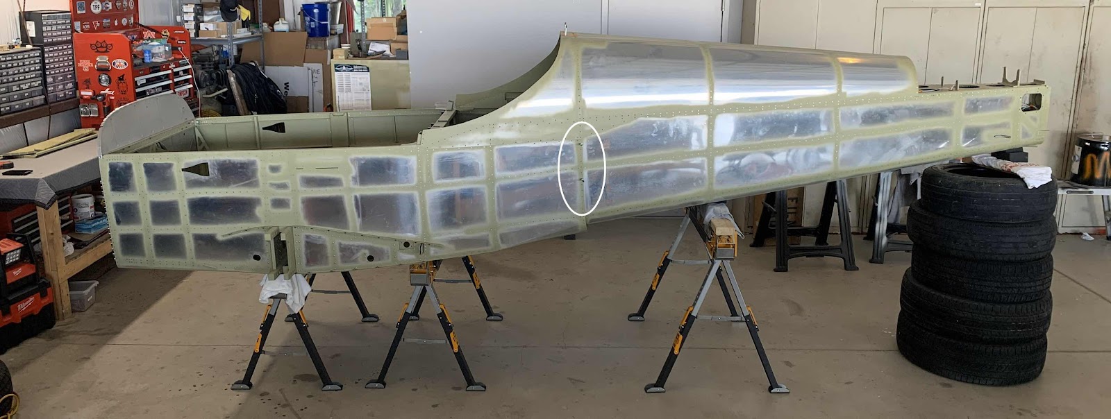
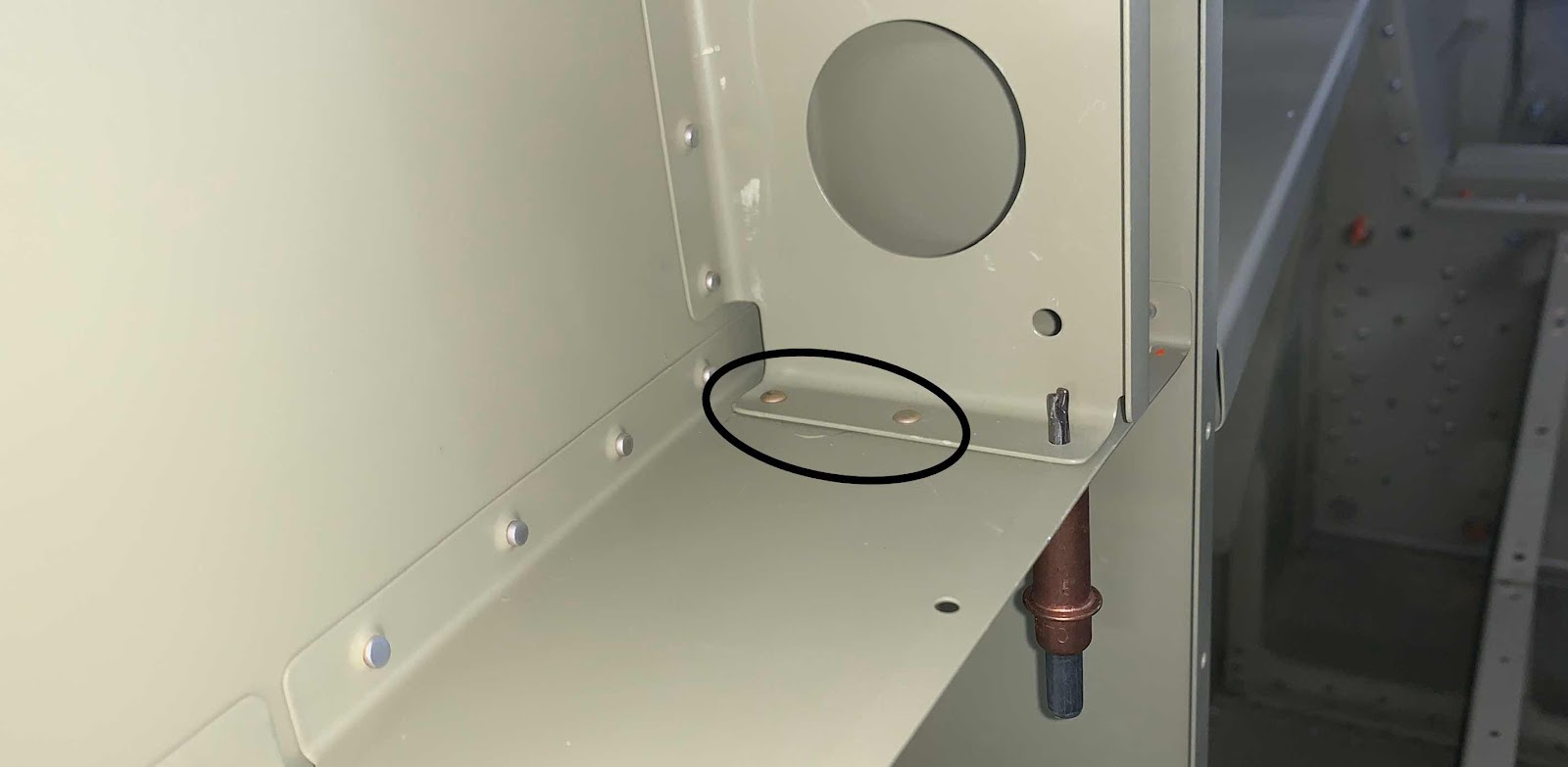
Today, I installed the F-01460-L & -R Intercostals.....and have a confession to make! I previously installed the F-01457-L & -R Gussets to the Upper Longerons AND the F-01405F Brace.....I should NOT have installed the rivets to the Brace (three rivets circled below). The Intercostals will also get riveted in this location. I guess I should have read the plans a little closer.
So, I had to drill out the six rivets (three on each side).
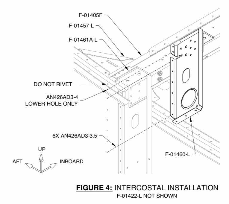
Once those rivets were removed, I could install the Intercostals. Here is what it looks like in the plans.....
.....and the left Intercostal riveted to the left Side Skin and Upper Longeron.....
.....and the right Intercostal riveted to the right Side Skin and Longeron.
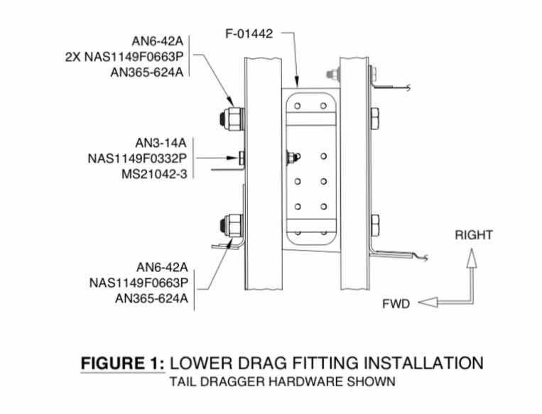
Since we were able to install all the remaining rivets in the forward Side Skin a couple of sessions ago, I could now final torque the bolts in the Lower Drag Fitting. Here is what it looks like in the plans.....
.....and on the plane (right side shown.....the left was completed with the left Side Skin).
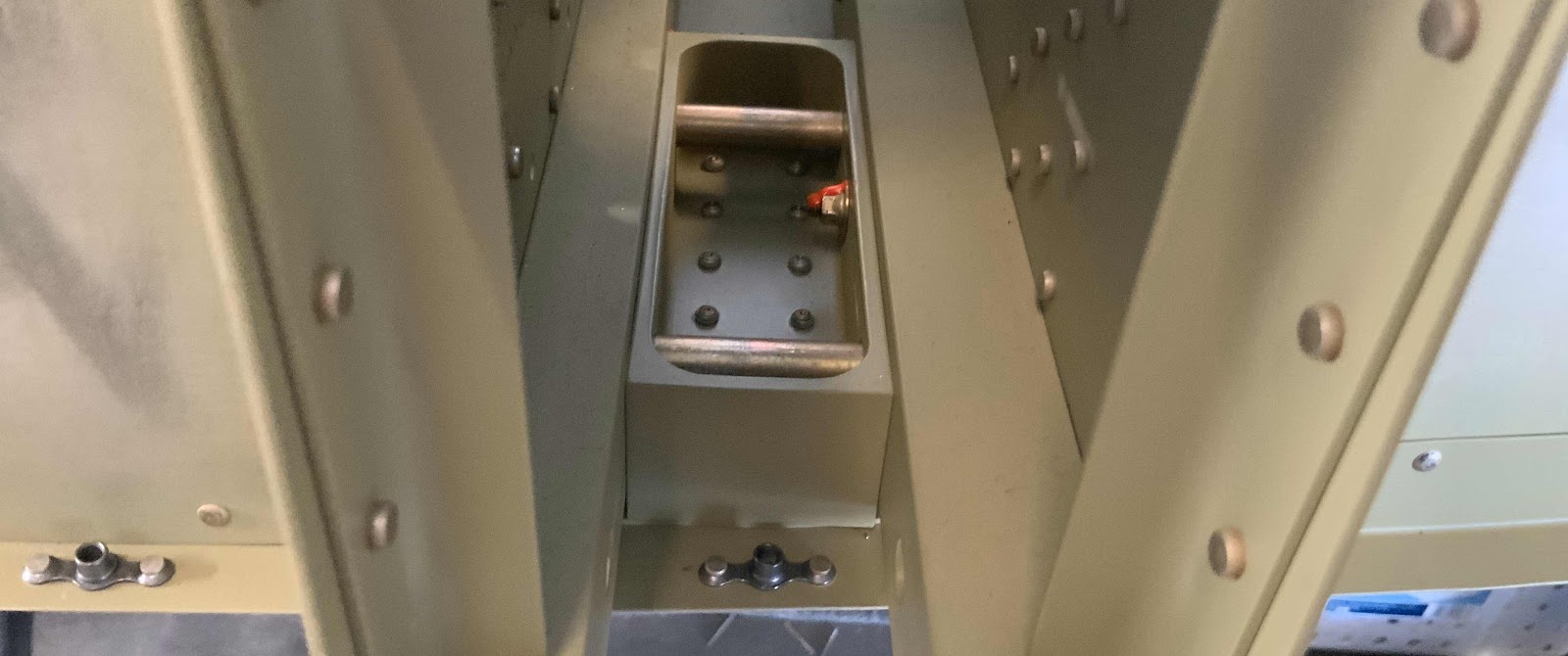
During the first session today, I installed the 16 K1000-08D on the F-01406A-L & -R Bulkheads. You can see the manufactured heads on the top Bulkhead and the nutplates and shop heads on the bottom Bulkhead.
Next, the six K1000-08D nutplates were installed on the F-01406C Bulkhead. Here are the nutplates installed on the Bulkhead.
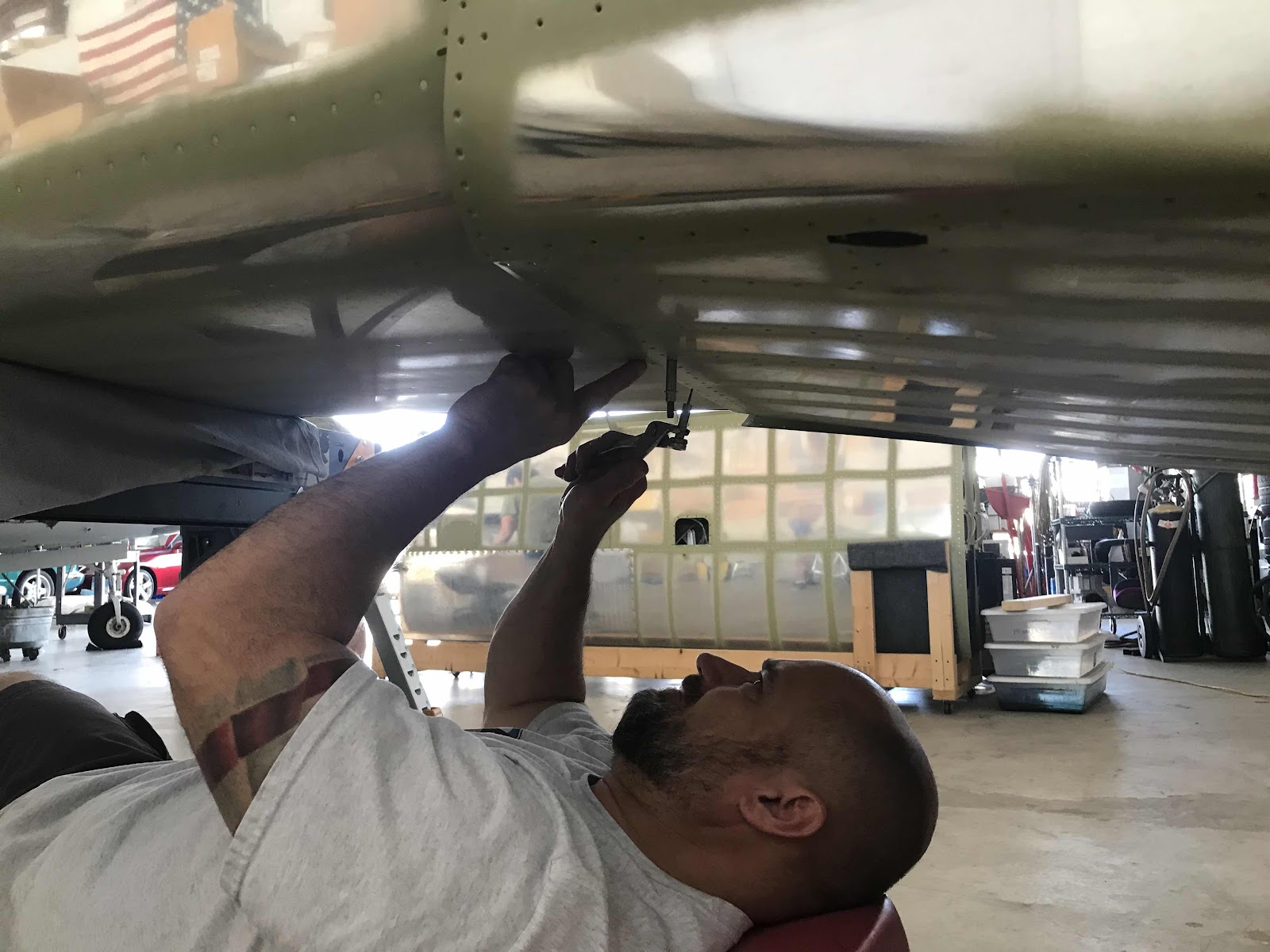
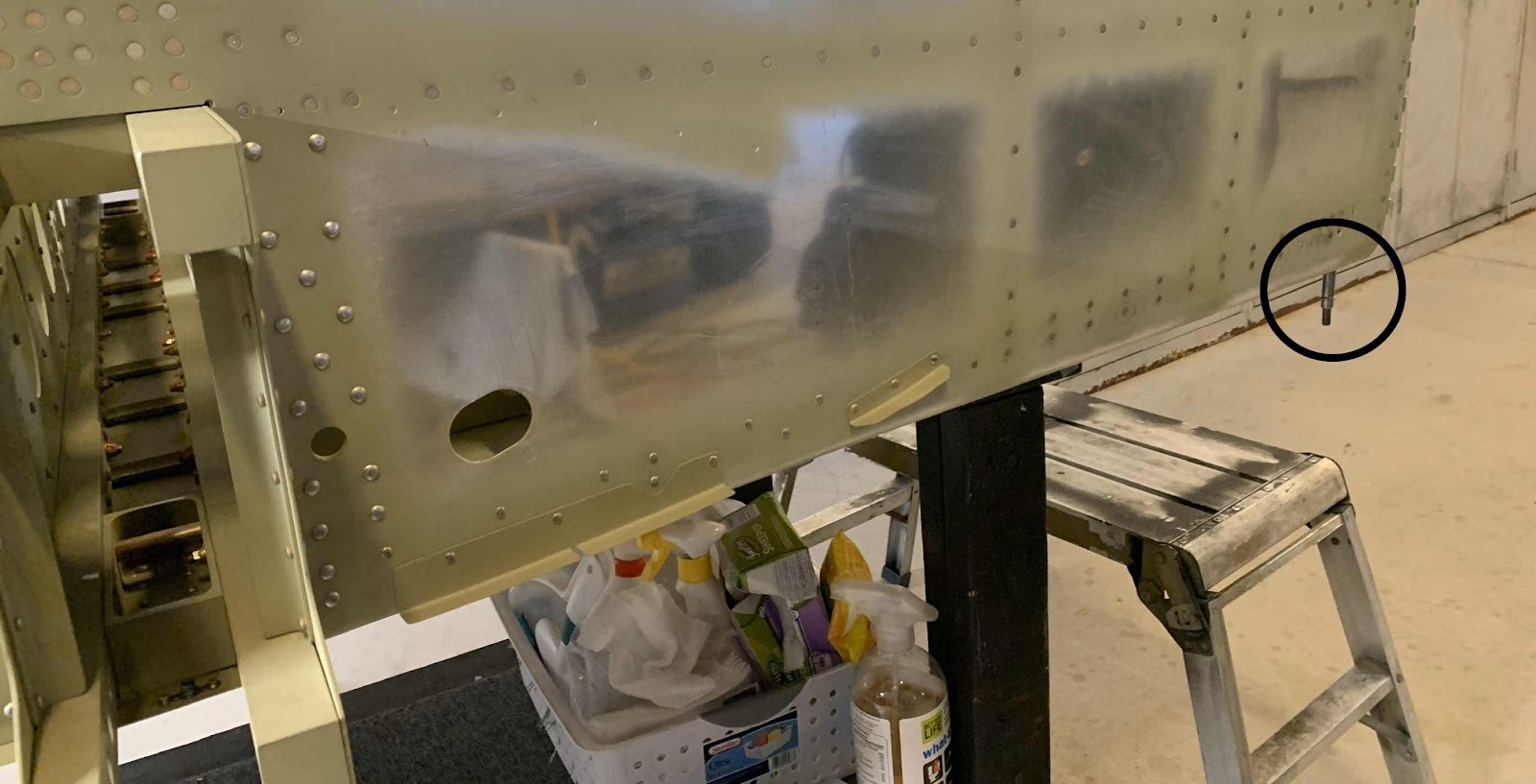
Today, the last rivets in the right forward Side Skin were installed.....almost. In the picture below, you can see the lone remaining rivet (circled) in the underside of the Skin. It can easily be squeezed, so I can do this one by myself during the next session.
The next rivet is the lone CR3212-4-5 Cherry Max rivet (circled below). I needed a total of six rivets, but only had five.....so, I’ve got to get/order a few extras.
Here is the “inside” or shop head side of the rivets.
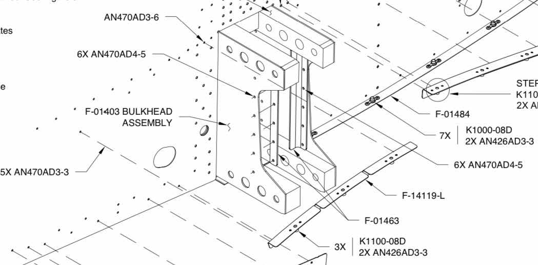
The “last” few rivets needing to be installed attach the F-14119-R Root Fairing Attach Angle (the left side is shown in the plans excerpt below) to the right Side Skin.
These rivets will be installed during the next work session. Until next time.....
While waiting on some riveting help, I decided to move on to the next section and start preparing some parts. As the section is titled, Aft Fuselage Attachment, there are only be a few parts that need to be prepared....the focus of the section is connecting the two “halves” of the Fuselage together.
The first two pieces to be prepared are the F-01406A-L & -R Bulkheads. The picture below shows the two completed parts. Each part had the holes deburred, edges cleaned, appropriate #40 and #30 holes dimpled, treated with Alumiprep, treated with Alodine and Akzo primed. The next step is to install the required nutplates.
The next part to get prepared is the F-01406C Bulkhead (top piece). This part was prepared in the same manner as the two Bulkheads above. Additionally, the two F-1231D Roll Bar Bases (to be used in Section 29) were treated with Alumiprep, Alodine and Akzo Primer.