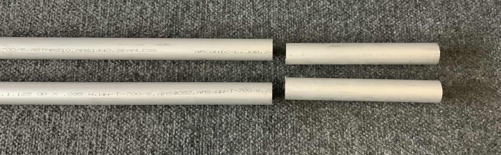
During today’s session, I started work on Section 23, Aileron Actuation. To start, the two CS-00012 Torque Tube to Bellcrank Pushrods had to be fabricated from AT6-035 x 1 1/8 to a length of 64 1/4”. Each Pushrod had to have a little cut off the end as shown below. I was able to use my bandsaw the make these cuts.
Each end of the Pushrods will get Threaded Rod Ends installed, so each end had to have rivet holes drilled in them. The template supplied by Van’s is shown below.....in several pieces. I found that the template didn’t fit completely right. Maybe it was something I did, but I couldn’t get the alignment holes on the template to....well, align with each other.

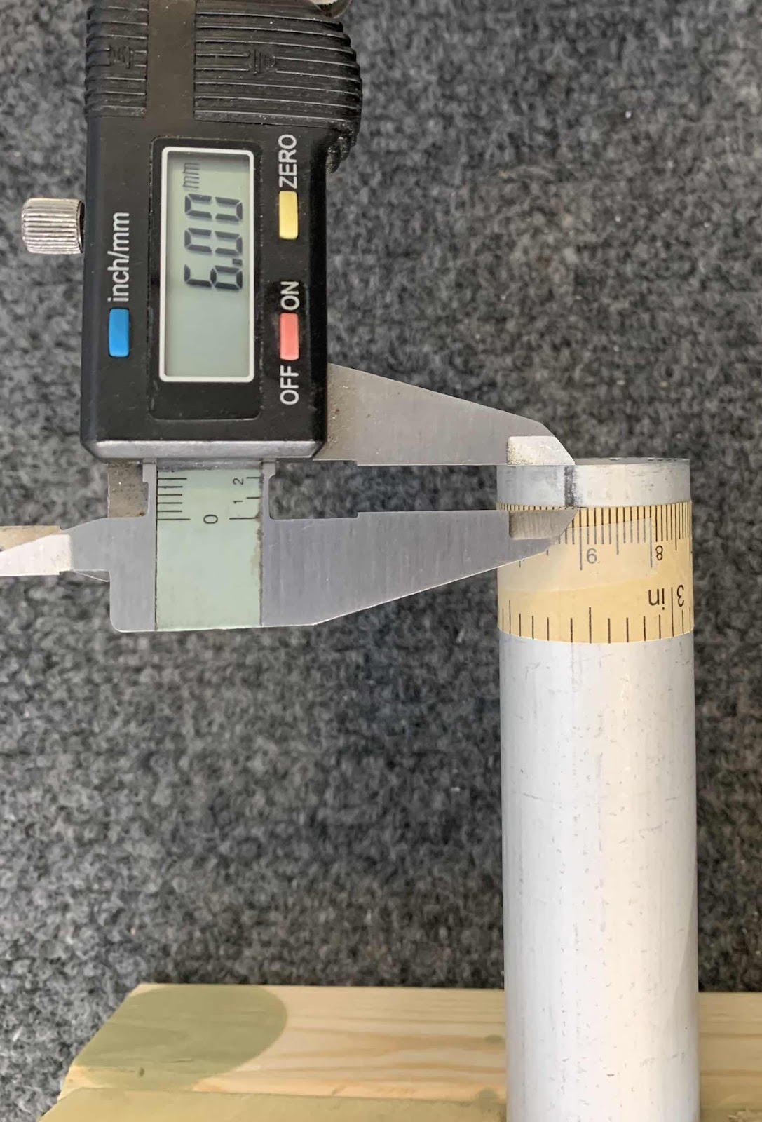
So, I decided to try something different. I got a paper tape measure and wrapped it around the Pushrod. I found the length to be 90mm. According to the template, six rivets will be used on each end to attach the Threaded Rod Ends. So, I divided 90mm by 6 and got each rivet location of 15mm. I then measured the distance of 6mm from the rivet locations to the end of the Pushrods.
Here is my template measred at 6mm from the end of the Pushrod.....
.....and here are three of the rivet locations marked at the 15mm spacing.

.....and here are three of the rivet locations marked at the 15mm spacing.
Next, all six of the marked rivet locations had #40 pilot holes drilled. Here are a couple of the holes after being drilled.

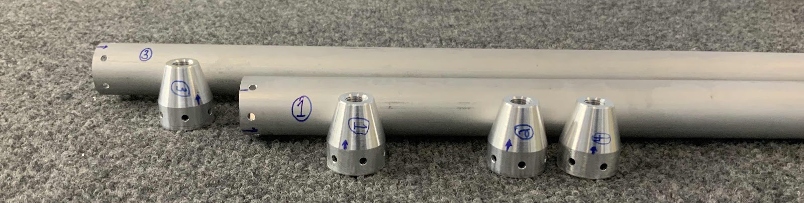
These are the four Threaded Rod Ends that will go in each end of the Pushrods.

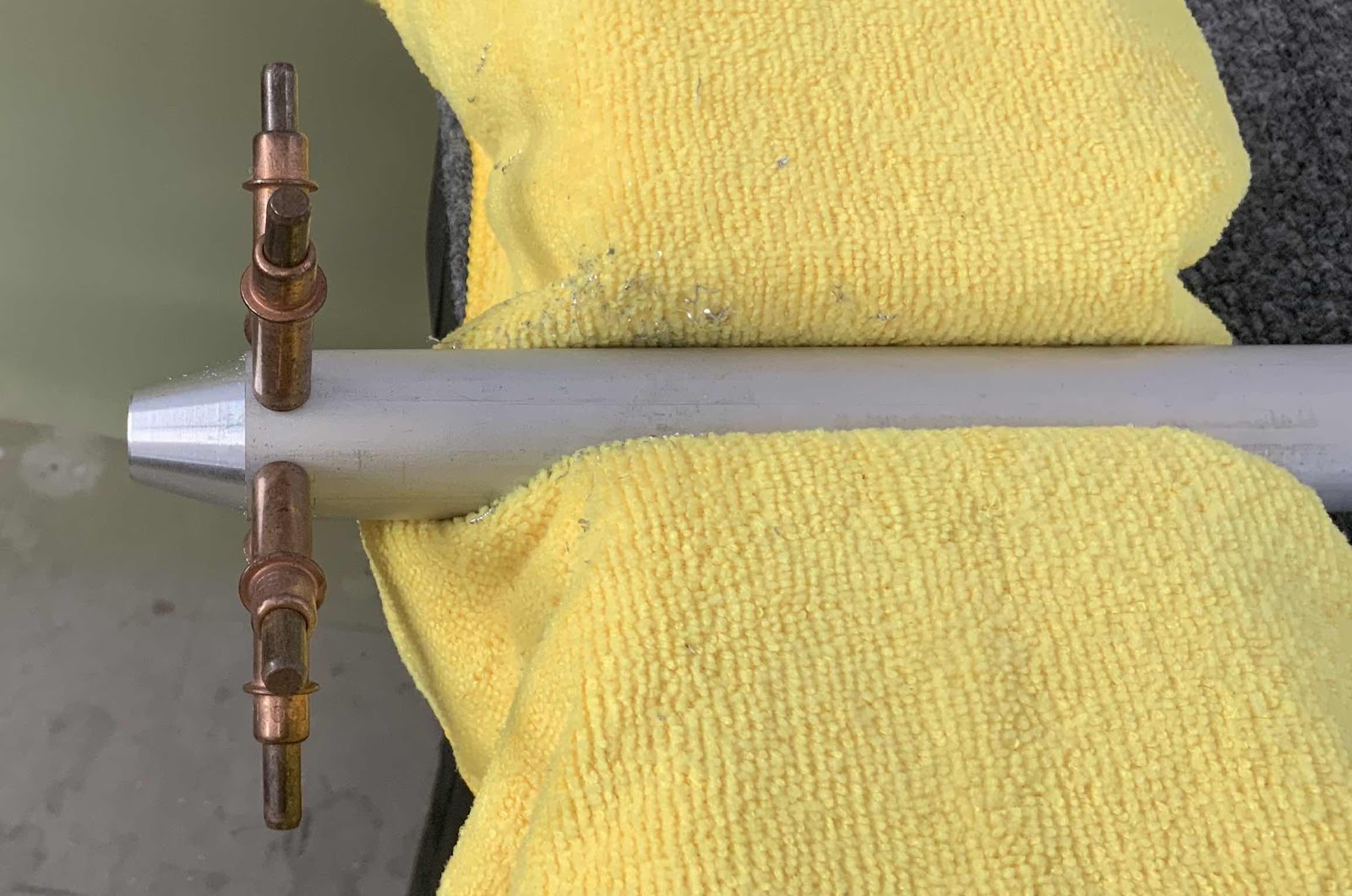
Next, the Threaded Rod End was then inserted into the Pushrod. “Proper alignment of the Threaded Rod End in the Torque Tube to Bellcrank Pushrod is when the end of the Tube coincides with the edge of the taper in the Threaded Rod End”. (If you look at the picture above, you can almost see a “line” where the taper starts). Once the proper alignment was achieved, the Threaded Rod Ends were match-drilled #30 using the #40 pilot holes and a cleco was installed in each hole as it was match-drilled. In the picture below, all six holes are show match-drilled with clecos installed.

Here is another angle. You can kinda see the tapered portion of the Threaded Rod End from this angle.
This process was completed for all four ends of the Pushrods. Prior to disassembly, each end of the Pushrods and the corresponding Threaded Rod Ends were numbers and one hole was marked on each to assure the same parts went back together in the same orientation.