
The F-01418A-L & -R Longerons and F-01488-L & -R Upper Engine Mount Brackets were treated with Alumiprep, Alodine, and sprayed with Akzo primer during the last session. During today’s session, they were riveted together using four CR3213-5-5 cherry rivets and 14 AN470AD4-6 solid rivets.
Pictured below is the right “Upper Longeron Assembly” showing the manufactured heads of the installed rivets.....
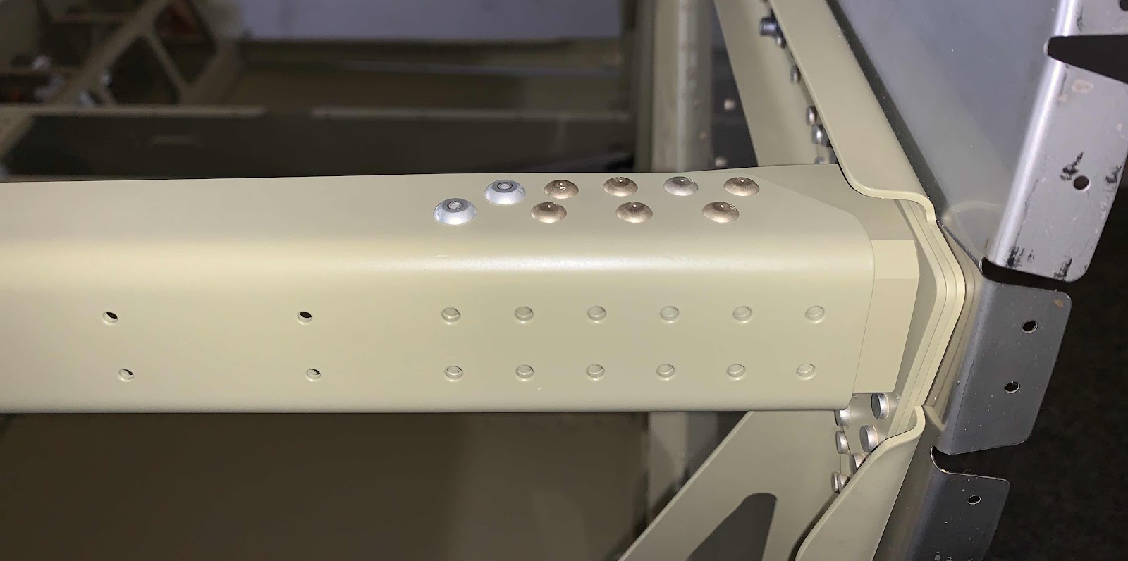
.....and the bottom side of the Upper Longeron Assembly also showing the manufactured heads of the installed rivets.....

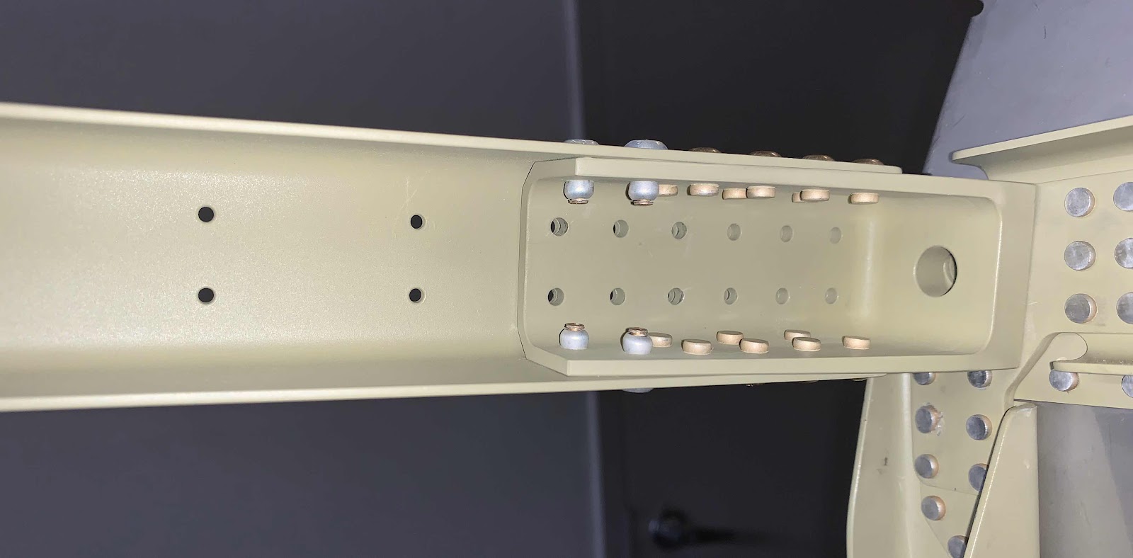
.....and the “inside” of the Upper Longeron Assembly showing the shop head side of the rivets.

The three pictures below show the same angles, but on the left Upper Longeron Assemby.


The next step was to prepare the left side piano hinge for the lower cowling. When the kit was delivered, it contained two 1/8 Piano Hinges approximately 8’ long. So, to start a length of 20 1/8” piece was cut as instructed. Additionally, only the lower 16 eyelets are need and the rest were removed (4 1/2 of them). The picture below shows the piece cut to length and the appropriate eyelets removed.

Next, a 3/32 (#40) pilot hole had to be drilled in the Piano Hinge. The plans provided the appropriate measurements for the location of the hole.....99.2 mm from the top and 6.4 mm from the outside edge. I marked the hole (which made the plus below), used a center punch to mark the center and drilled the #40 hole. Lastly, a reference line 2.4 mm was drawn lengthwise on the inside edge.
