Saturday, February 10, 2024

Panel Installation (Part 3)

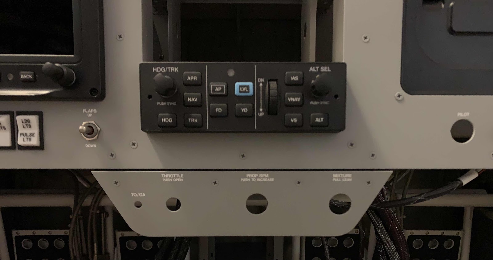
These two pictures show the panel bracket (also made by Aerotronics) for the control cables mounted underneath the panel frame.  The holes in the bracket from left to right are: 

Go Around…..Throttle….Prop…..Mixture


This last picture shows the GTN750Xi mounted in the panel.  There was a fair amount of work to get the mounting tray installed the way I liked it….correct height and depth as compared to the autopilot controller and general visuals of the unit compared to the rest of the panel.  For the installation, I installed screws through the countersunk holes already in the mounting bracket, then through the instrument panel standoffs.  I had to drill a few holes in the standoffs, but the installation wasn’t very difficult…..just took some time to get right.

Tuesday, February 6, 2024

Wing Root Filters - Aircraft Specialty (Part 2)

The work, pictures and video from this post are from June 19, 2021.

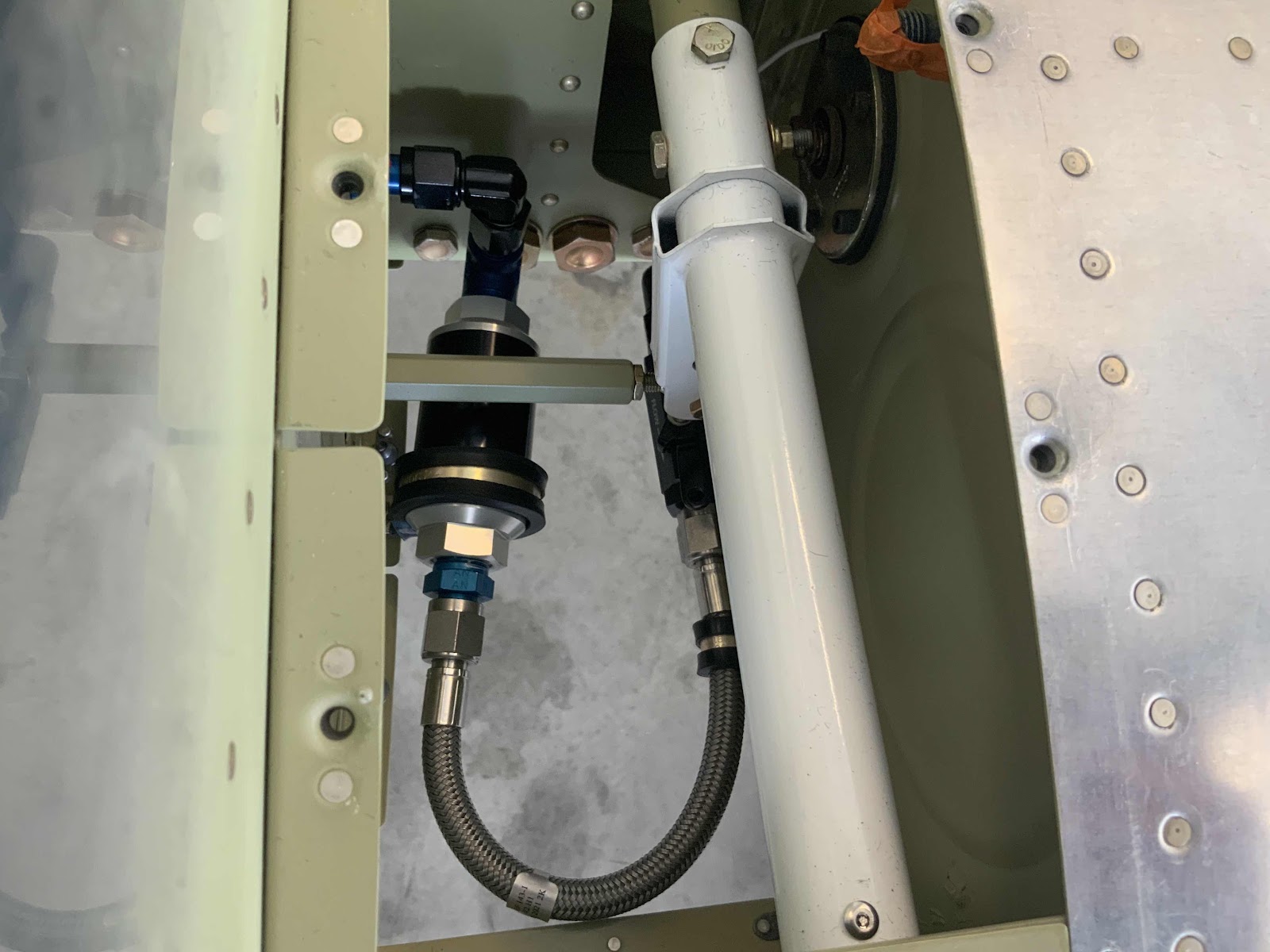
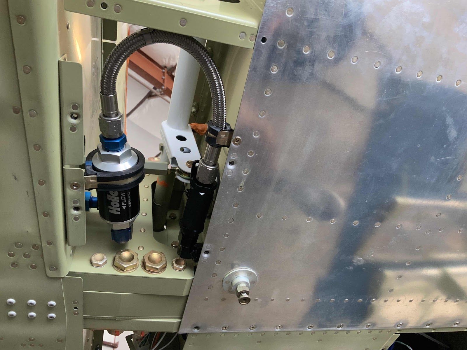
Those two “assemblies” shown in the part 1 were installed in the aircraft wing roots as shown in these four (4) pictures.  This picture is looking down at the left wing root…..

…..and looking up at the left wing root.

This picture is looking down at the right wing root…..

…..and looking up at the right wing root.


The final remaining step is to safety wire the fuel valves to the “OPEN” position.  The website says the only time these valves should be in the “CLOSED” position is during the Condition Inspection for servicing the fuel filters.

Install Complete

Wing Root Filters - Aircraft Specialty (Part 1)

In June of 2021, we purchased and installed the Wing Root Filter Retrofit from Aircraft Specialty.  

The work, pictures and video from this post are from June 18, 2021.

Here are the installation instructions from their website.  (Starts on page #6)

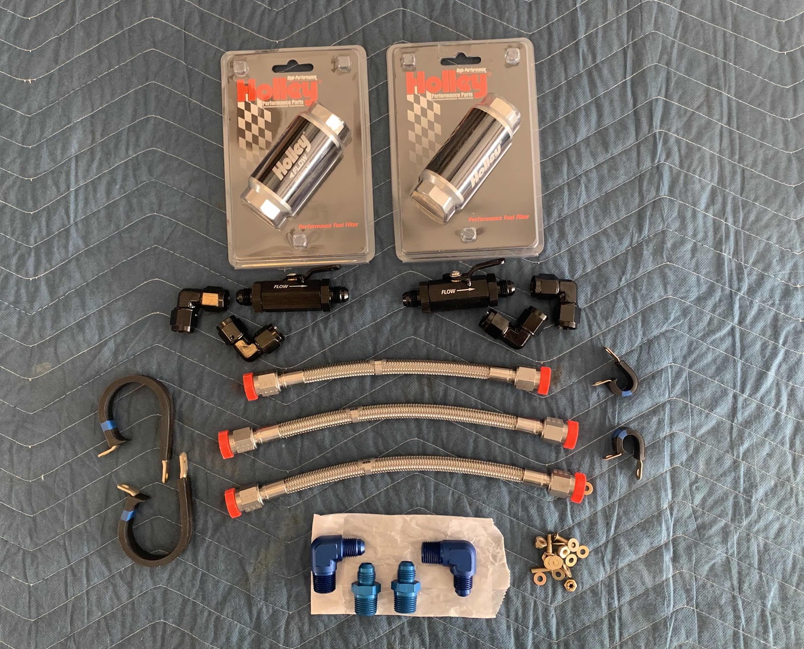
These are the items we received from Aircraft Specialty for this kit.  It comes with very quality parts and pieces and was fairly easily to install.

To start, we removed the Andair fuel filter and fuel line to the fuel selector.

Here is the Andair fuel filter and fuel line completely removed.

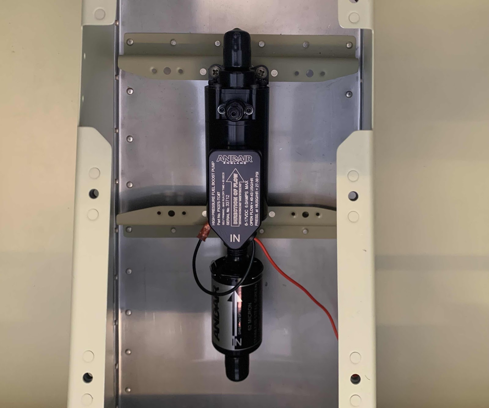
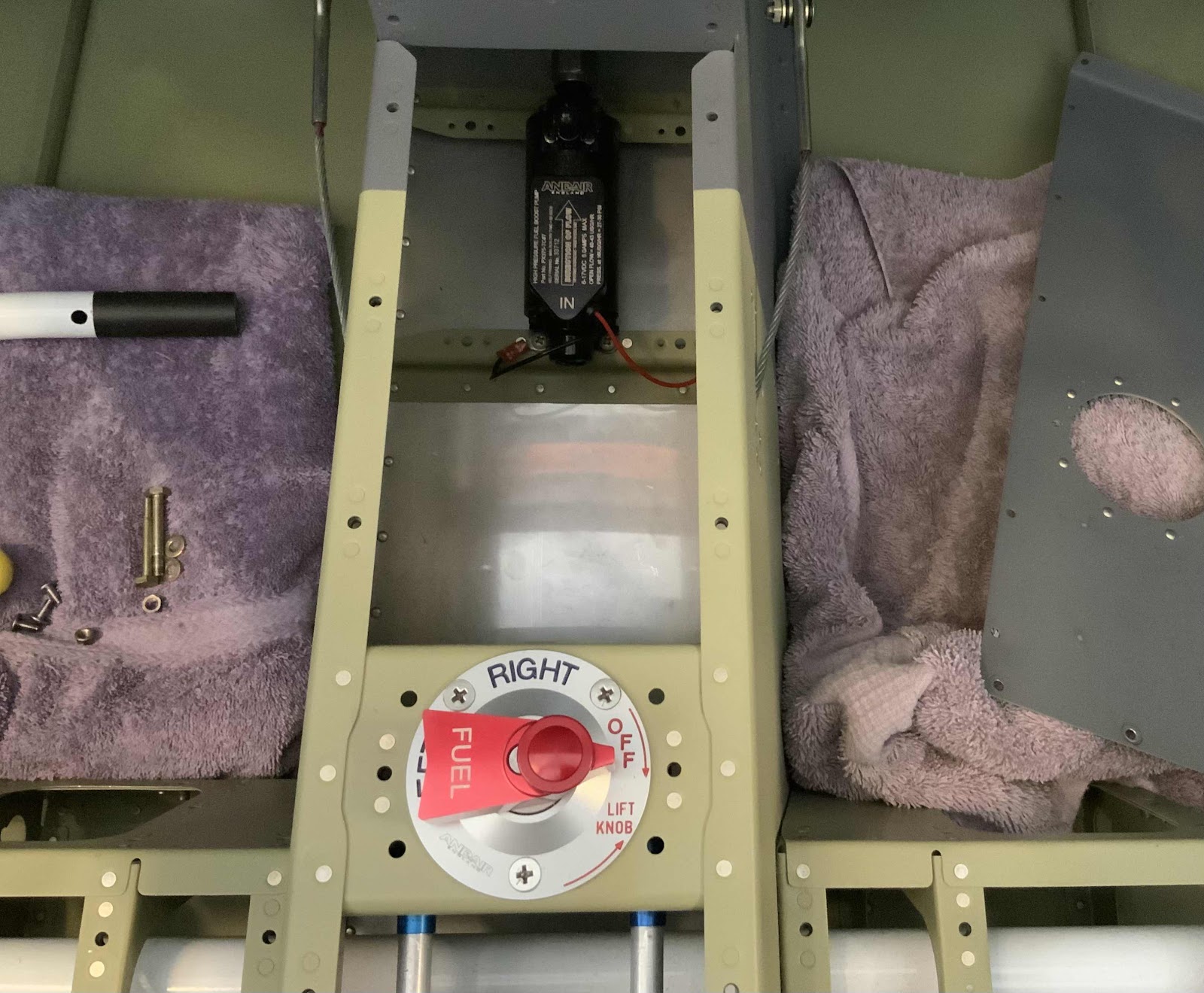
One end of the new ASF 140RT-6 R(X) H3 fuel hose was connected to the fuel pump where the fuel filter used to be.  The other end of the hose was connected to the fuel selector.  (You can see that connection just above the word “RIGHT” on the fuel selector).

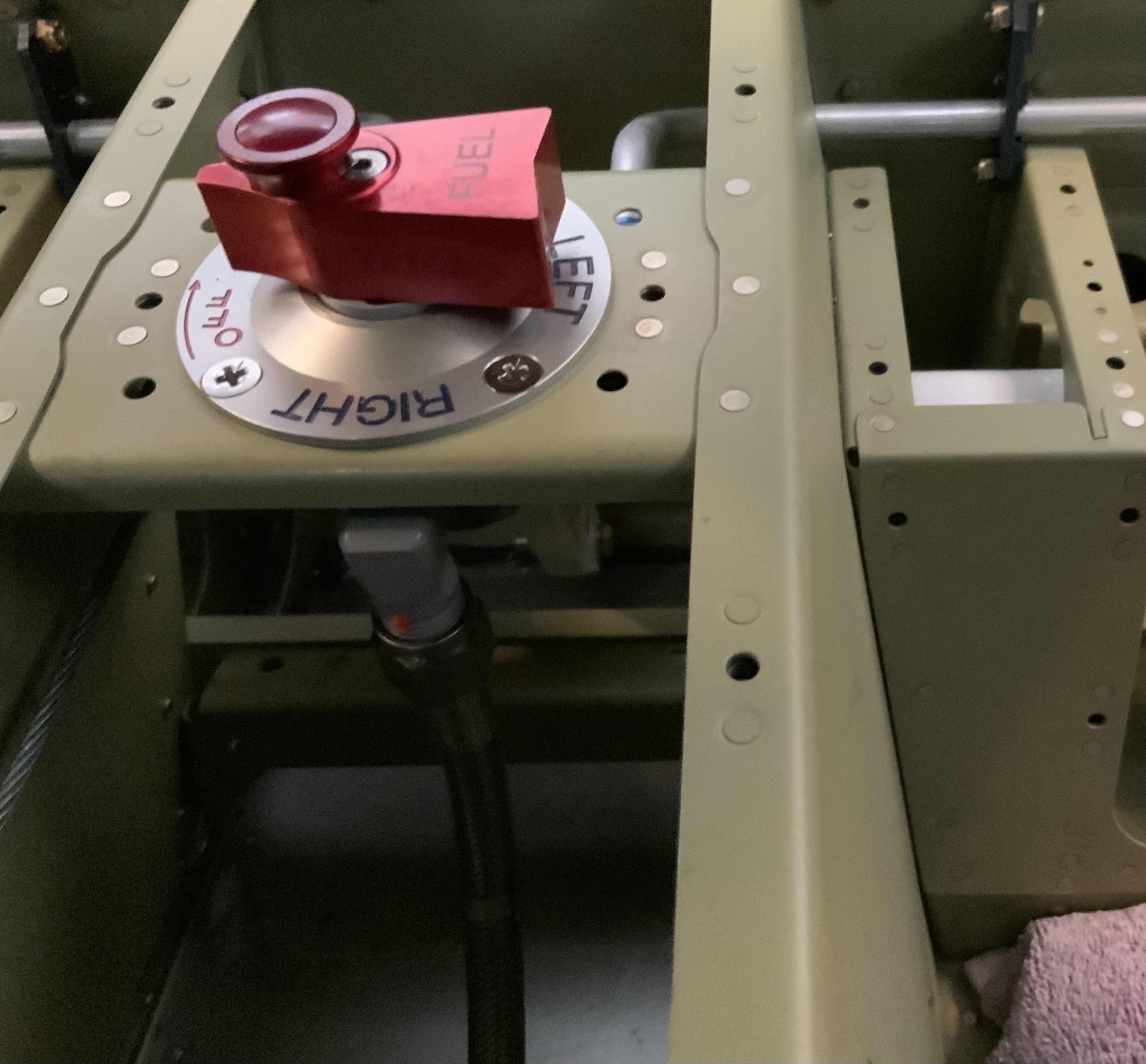
Here is another angle of that same connection.


With the exception of the four (4) adel clamps and associated hardware, the remaining parts in the kit were assembled to look like this.  One “assembly” will be installed in each of the wing roots.

Monday, February 5, 2024

Aerosun VX (Wingtip Landing/WigWag Lights) - AEROLED’s (Part 1)

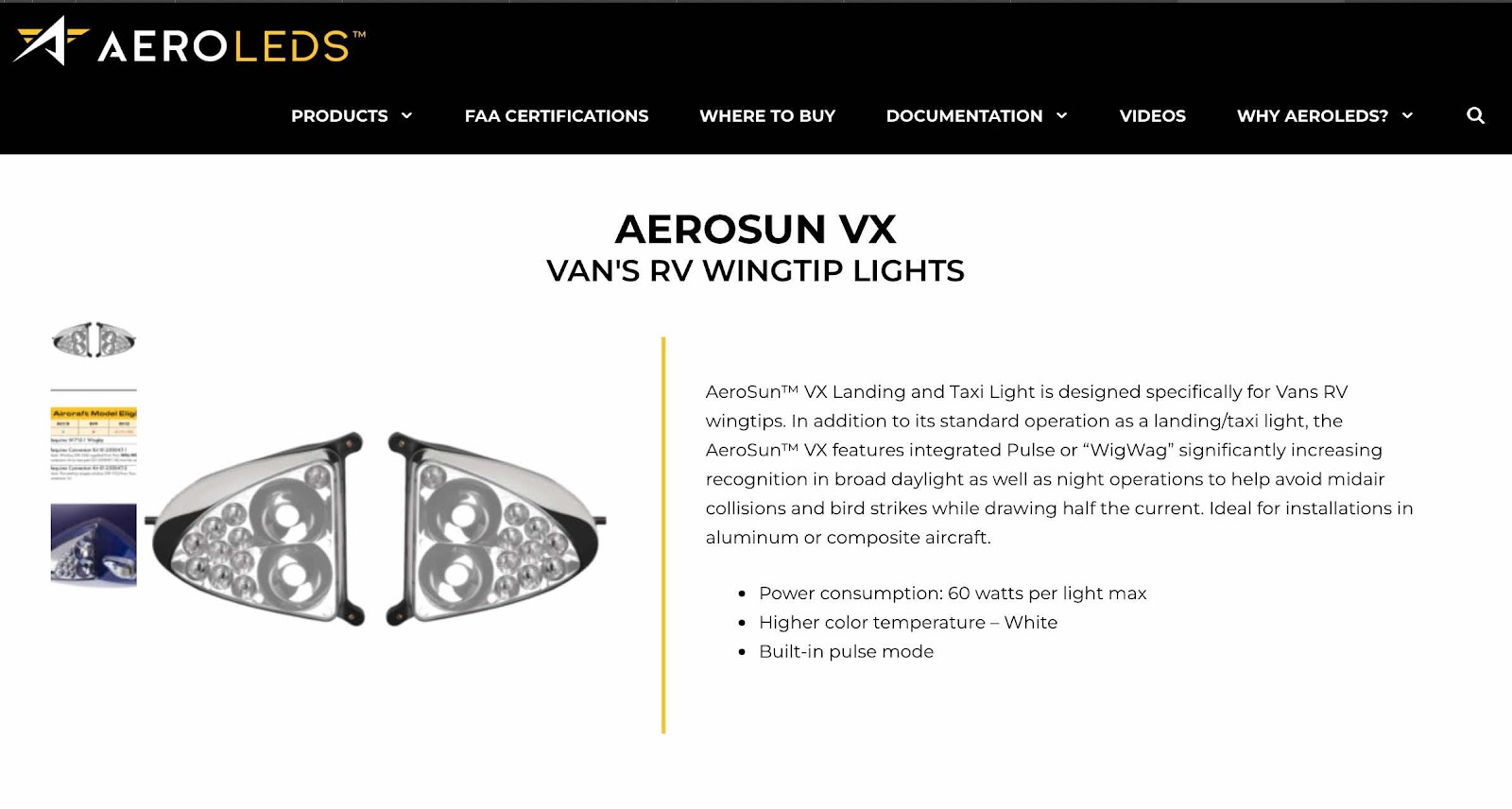
For the wingtips, we will install the Aerosun VX (Wingtip Landing/WigWag Lights) from AEROLEDS.
(Van’s part # LL-205)

It is my intent to use these lights strictly as Wingtip Landing Lights and WigWag’s.  I will document the installation of these lights here when I reach that point in the build.

Here is the manual and installation guide from their website.

For the installation of the AeroSun VX lights, please see:

Section 24 - Wings, Wing Tip (Parts 13 - 11) - (also included below)

Sunspot 36 LX (Leading Edge Landing Lights) - AEROLED’s (Part 1)

For the leading edges of the wings (the leading edges were prepunched by Van’s), we will install the Sunspot 36 LX (Landing Lights) from AEROLEDS.  (Van’s part # LL-00008)

These lights are Landing Lights; however, it is my intent to use them as “Taxi Lights”.  Here is what I mean…..since we are building a taildragger, I plan to adjust these lights to shine more on the ground in front of the plane when the tail is on the ground.  Thus, acting more like a “Taxi Light”.  I will adjust appropriately and use the Aerosun VX Wingtip Landing/WigWag Lights as the “Landing Lights”.

I will document the installation of these lights here when I reach that point in the build.

Here is the manual and installation guide from their website.  Additionally, the link above and information below to AEROLED’s references the new “optimized” version of the “Sunspot LXi” not to the version I purchased and will be installing.  I have the original Sunspot LX version of the landing land.

Pulsar NS (Navigation/Strobe Lights) - AEROLED’s (Part 1)

For the Navigation/Strobe Lights, we will install the Experimental Pulsar NS (Navigation/Strobe Lights) from AEROLEDS.  (Van’s part # LN-201-1)

I will document the installation of these lights here when I reach that point in the build.

Here is the manual and installation guide from their website.


Suntail (Strobe/Position Light) - AEROLED’s

For the tail light, we have already installed the Experimental SUNTAIL (Strobe/Position Light) from AEROLEDS.
(Van’s part # LN-210-1)

Here is the manual and installation guide from their website.


For the installation of the SUNTAIL, please see:

Section 12 - Empennage Fairings (Parts 7 & 4) - (also included below)

Sunday, February 4, 2024

Engine Installation (Part 3)

The work, pictures and videos from this post are from September 17, 2021.

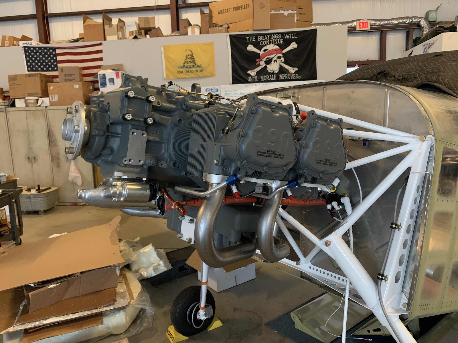
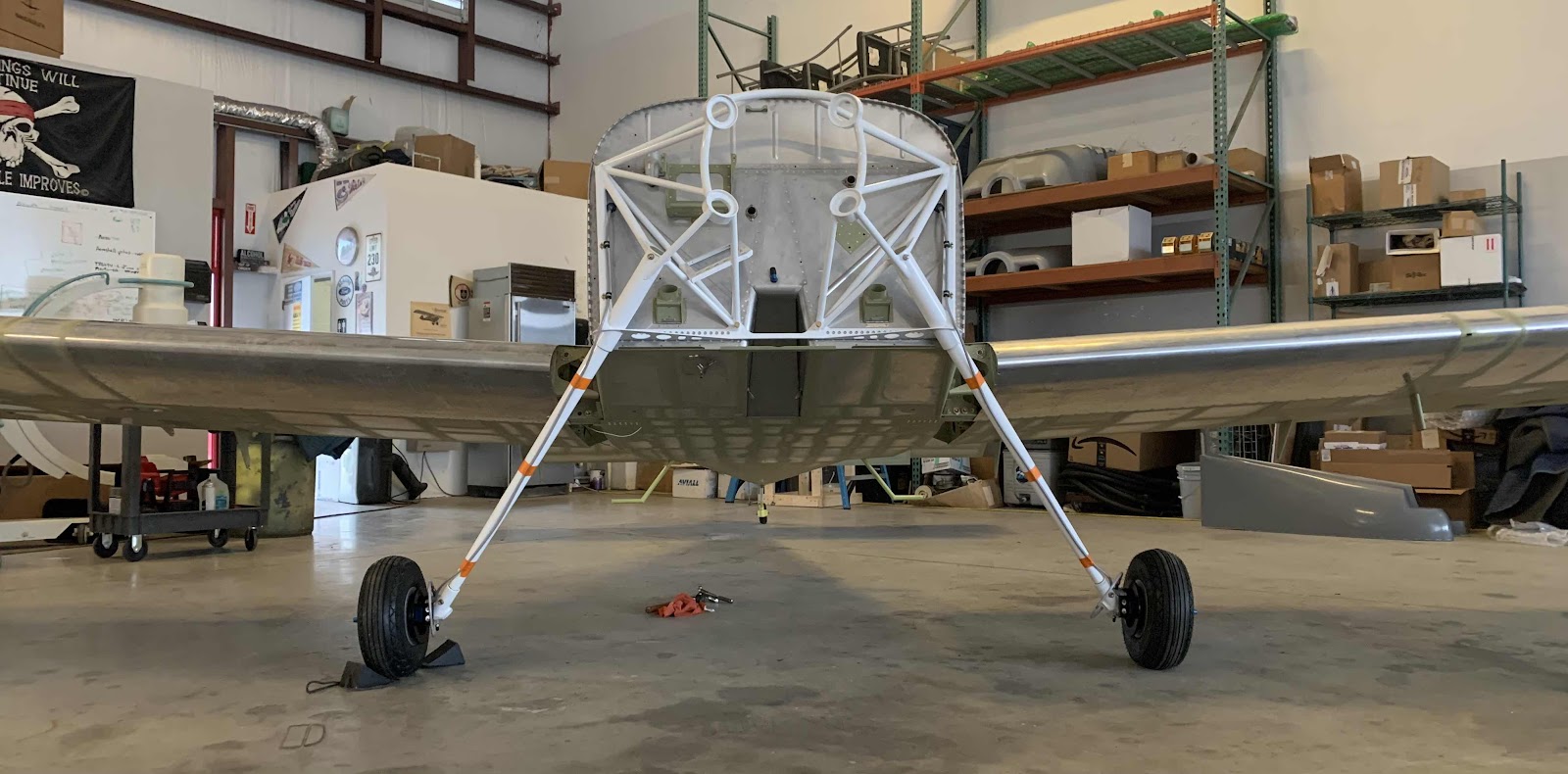
During this work session:  Jeff, Roger and I finally hung the engine on the airplane.  It was a very satisfying feeling to finally get the engine out of the box and onto the airplane!  We attached it to the plane’s engine mount using the included EA DYNA BOLT Dynafocal Engine Mounting Bolt Kit.  Here are a several pictures and videos of the install…..


After the engine was attached to the motor mounts, we installed all of the fluid fittings as outlined on pages 43-05 and 43-06 of the build plans.  These fittings included:  the lower oil port fitting, upper oil port fitting, oil pressure port fitting, oil temperature sensor, fitting to the fuel pressure sensor, fitting to the fuel flow sensor, the fuel vent and overflow tube, fuel pump inlet fitting, fitting to manifold pressure sensor, and the IE RC-1 tach drive cap.

Engine Installation (Part 2)

The work and pictures in this post are from September 16, 2021.  This is what the engine mount looks like on the plane ready to accept the engine.

To start this section, the ES PC680 Odyssey Battery is installed into the FF-01403 Battery Box (previously installed on the firewall) and secured with the F-01403A Battery Box Angle.  Then, the WH-P25 2AWG Ground Strap is installed on the aircraft’s firewall ground, but is left disconnected from the battery negative.  Finally, the WH-P769 Starter Relay Power Cable is attached to the battery positive (along with the insulated boot).

This shows the ES 24115 Master Relay (top) and the ES 24021 Starter Solenoid (bottom) attached to the firewall.  Also seen here is the WH-K1066 Relay Interconnect Bar attached (with the installed heat shrink) between the two parts.

Page 43-04 of the build plans includes several electrical connections made to the Master Relay and Starter Solenoid.  They include:  WH-P912 Battery Power Wire, WH-P769 Starter Rely Power Cable, ES Diode Master, ES Diode Starter, WH-P16 Starter Relay to Starter Wire and the WH-P910 Starter Disengage Wire.  These two pictures show all of those connections completed per the plans.

Sunday, January 28, 2024

RV-14 Tailwheel Assembly - JD Air

In June of 2021, I purchased and installed the RV-14 Tailwheel Assembly including Steering Link from JD Air. The work and pictures in this post are from June 14, 2021.

Here are the instructions I used for the installation that are published on their website.

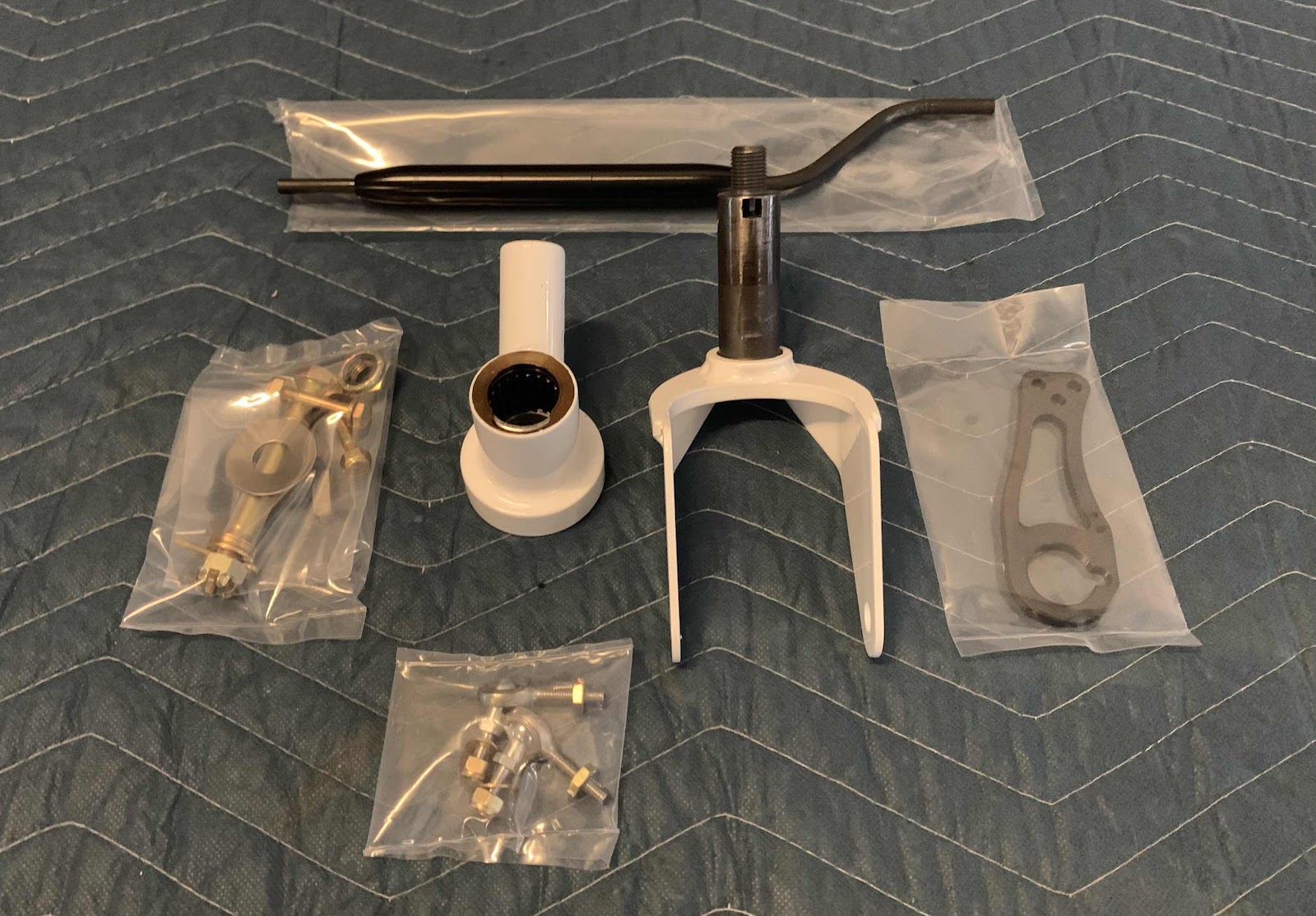
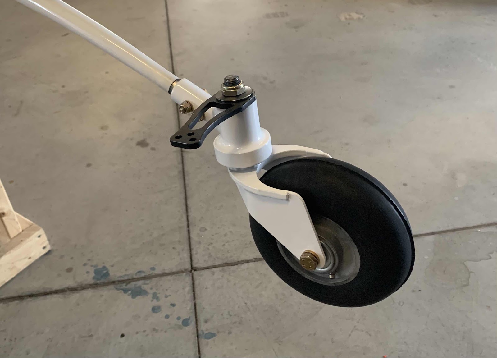
These are the parts and hardware that comes with the kit.  I decided not to use the Light Weight Tire (available option) and used the stock U Tail Wheel 6” from Van’s.  I flew an RV-7 for a couple of years that had one of the Light Weight Tires and I wasn’t a big fan of it.  It gave the plane a noticeably rough ride while taxiing that wasn’t very comfortable…..in my opinion.  I know other RV owners that love them, so to each his own.

The first step is to install the Dual Bearing Yoke onto the U-00016 Tail Gear Spring with (2) AN3-12A bolts, (2) AN960-10 washers and (2) AN365-1032A nuts.  This is the same way the Van’s stock Yoke is installed, but they just use different hardware. 


Now, the Tail Wheel Fork is installed through the Yoke, the Adjustable Single Control Arm, the Custom 1/2” Belleville washer and a AN364-820A nut holds everything together.


Next, the stock Van’s U Tail Wheel 6” (my preference over the Light Weight Tire) is installed on the Fork using an AN6-31 Bolt, (2) AN960-616(L) washers, (1) AN960-616 washer, an AN310-6 castle nut and (1) MS24665-238 cotter pin.


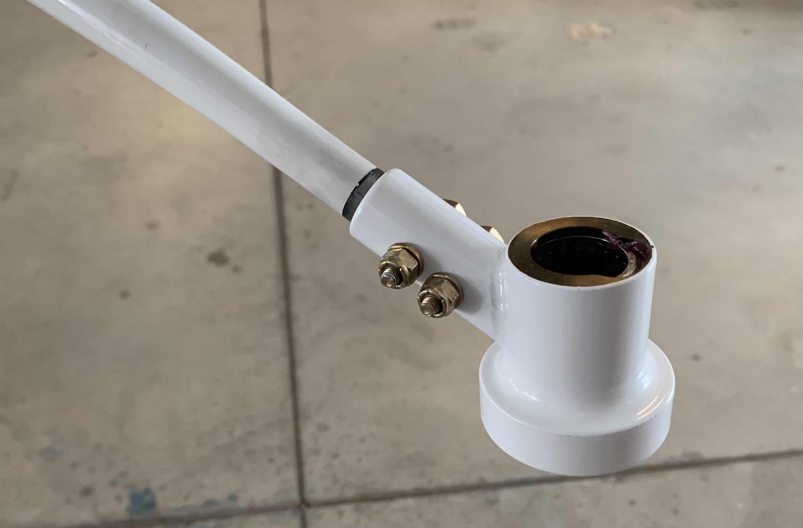
Finally, the Tail Link is installed following these instructions on their website.  These two pictures show the entire assembly completely installed.


Rudder Pedal Extensions - JD Air

In March of 2020, I purchased and installed the Rudder Pedal Extensions from JD Air.  The installation of this hose kit was completed in:

Fuselage, Section 33 - Rudder and Brake System, Part 9 (also included below)

Here are the installation instructions published on their website.

Gear Leg Brake Hose Kit - Aircraft Specialty

In June 2021, I purchased and installed the Gear Leg Hose Kit from Aircraft Specialty. The installation of this hose kit was completed in:

Fuselage, Section 40B - TD Gear/Engine Mount, Part 6 (also included below)

Here are the installation instructions published on their website.

Cabin Brake Hose Kit - Aircraft Specialty

In March of 2020, we purchased and installed the Cabin Brake Hose Kit from Aircraft Specialty.  The installation of this hose kit was completed in:

Fuselage, Section 33 - Rudder & Brake System, Parts 10 - 13 (also included below)

Here are the installation instructions published on their website.

Cabin Fuel Lines - Aircraft Specialty

In March of 2020, I purchased and installed the Cabin Fuel Line Package (also known as the Complete Firewall Aft Hose Kit) from Aircraft Specialty.  The installation of this hose kit was completed in:

Fuselage, Section 31-Fuel System, Part 4 - 6 (also included below)

Here are the installation instructions published on their website.

RV Max Flap Actuator - PH Aviation Services (Part 3)

The work and pictures from this post are from November 12, 2022.

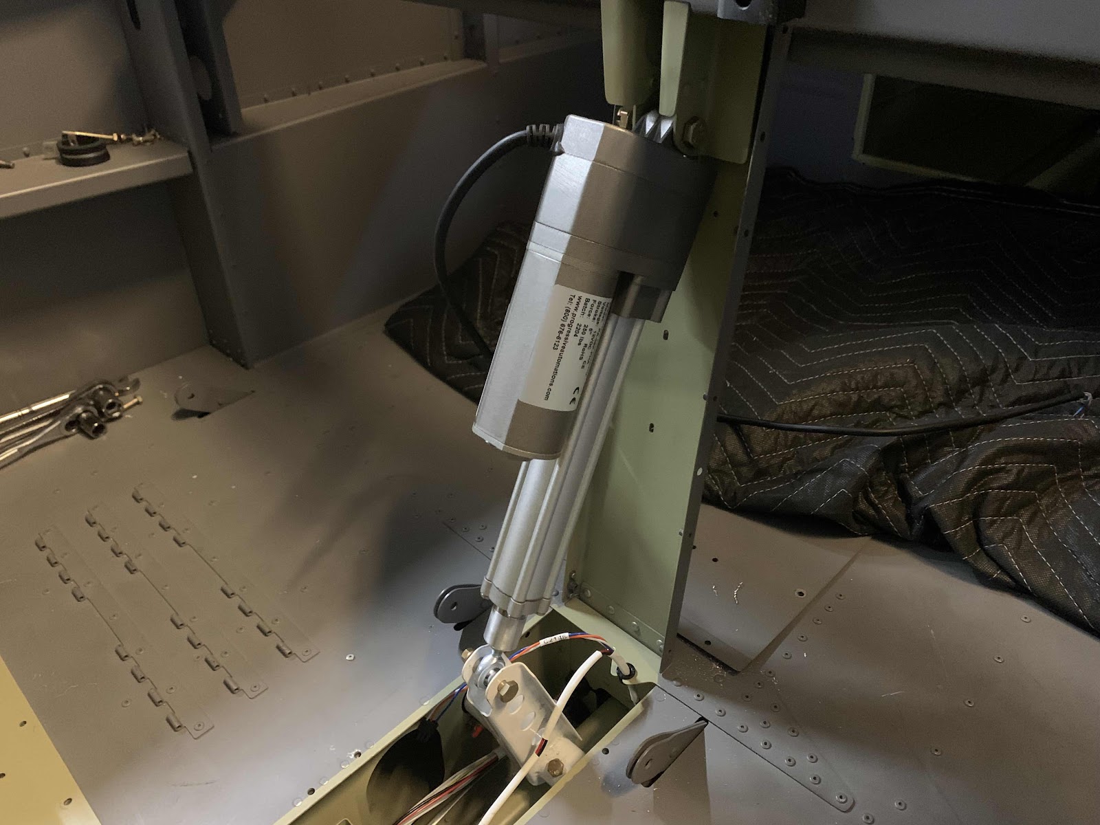
Finally, here is the completely installed RV Max Flap Actuator.  Upper portion of the Actuator is attached to the modified Flap Motor Brackets with the following hardware:

(1) AN5-13 bolt
(2) NAS1149F0563P washers (AN960-516)
(4) NAS1149F0532P washers (AN960-516L)
(1) AN310-5 Castle Nut
(1) MS24665-134 Cotter Pin

The bottom portion of the Actuator is attached to the WD-1013A Flap Crank using the stock hardware called out in the build plans page 34-05.  This includes:

(1) AN4-12A Bolt
(2) Bushing-AL .259x.375x.168
(1) NAS1149F0463P
(1) MS21042-4


The upgraded PH Aviation Services RV Max Flap Actuator is now completely installed.  The only remaining step is to make the electrical connections.  I will do that later when I start making the electrical connections for the entire plane.

RV Max Flap Actuator - PH Aviation Services (Part 2)

The work and pictures from this post are from November 11, 2022.

As the previous post mentioned, there are some modifications that need to be made to the stock parts in order for the RV Max Flap Actuator to work properly.  

The PH Aviation website publishes installation instructions titled Installation of PH Aviation Flap Actuator in RV-14.  These are the instructions that I followed for these modifications and installation.

The first page of the instructions says the F-01466-L & -R Flap Motor Brackets will need to be modified and that this should be done PRIOR to installing them as instructed in the build plans on page 32-07.  Since I found out about the Actuator after I completed Section 32, I will have to remove the previously installed Flap Motor Brackets.  As a result, I also decided to order two new Flap Motor Brackets from Van’s…..I just wanted new stuff since I had to drill out all the rivets in the original Brackets.

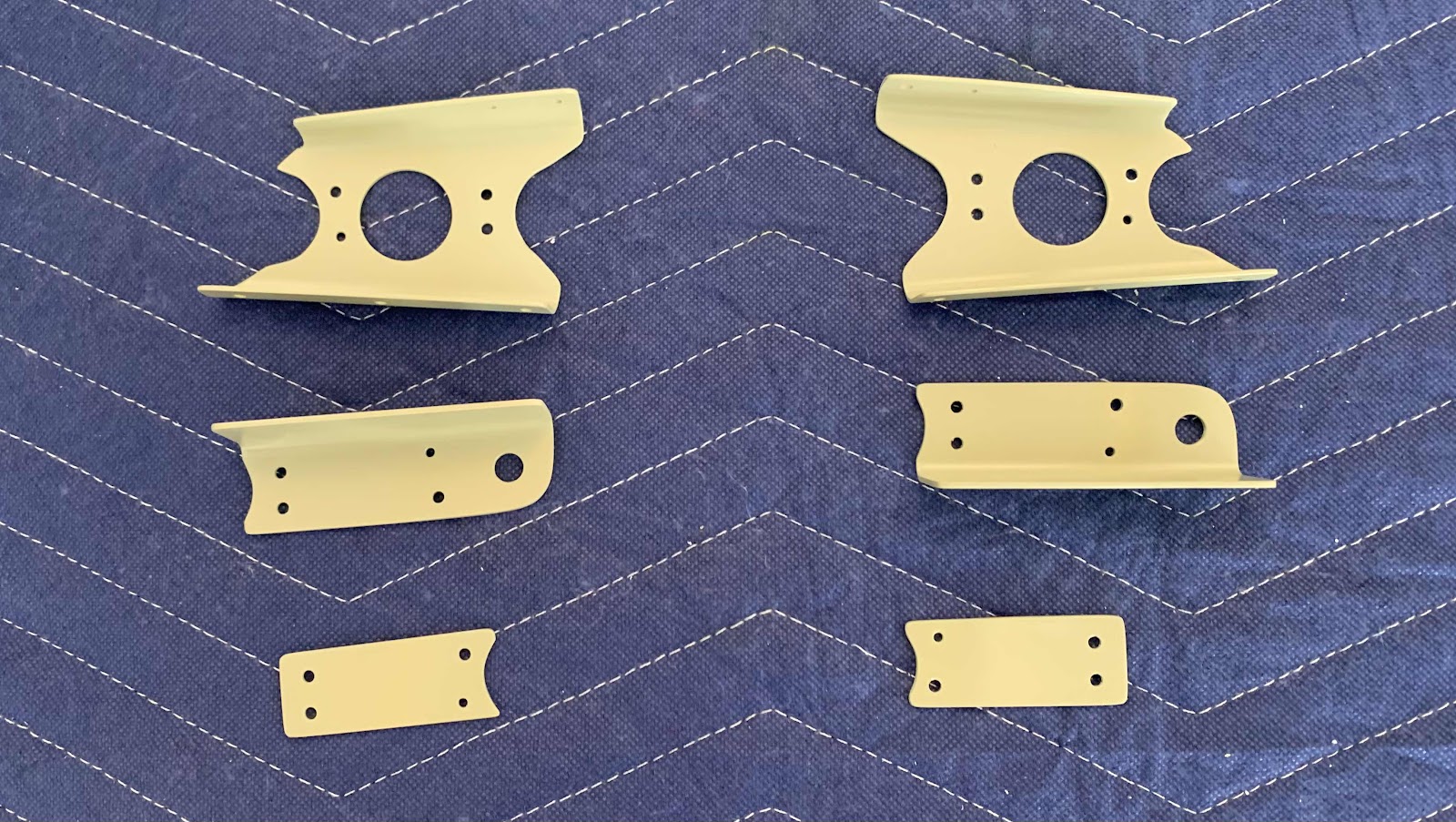
Now, the picture below shows the progress of the modifications starting at step #19 of the instructions.  I didn’t feel the need to post all of the same fabrication pictures that are included in the instructions in step #1 through steps #18.  The top two pieces are the modified stock Flap Motor Brackets from Van’s (the new ones I ordered).  The middle two pieces are the 1” x 1” x 0.063” aluminum angles after being fabricated.  The last two pictures are the 0.063” Shims after being fabricated.

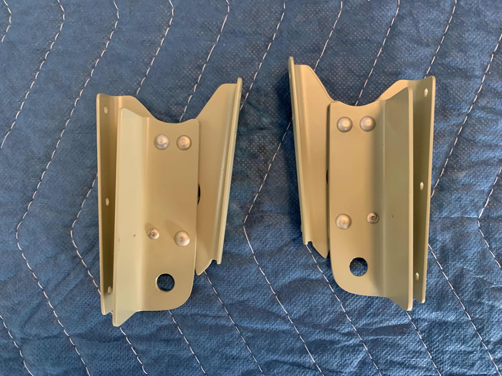
The Angles and Shims for each “side” were clecoed and riveted to the modified F-01466-L & -R Flap Motor Brackets using (3) AN470AD4-5 and (1) AN470AD3-5 rivets.

Next, the modified Flap Motor Brackets are riveted to the front to the F-01405F Mid Fuse Brace using (2) AN470AD4-4 and (2) AN426AD3-4 rivets.


The back of the modified Flap Motor Brackets are riveted to the F-01405G Flap Motor Channel using six CR3213-4-2 CherryMax rivets (two of the rivets are hidden behind the C-01438 Canopy Latch Torque Tube).  The bottom two holes were used with the old, longer Brackets and will be left open for the new, shorter Brackets.  You can see a little scraped paint on the Torque Tube from removing the previous rivets in the old Brackets…..

…..so, obviously, I had to clean that up and re-paint those areas.  This is why I like using the SEM paint products…..look how nicely the new paint blends with the old paint.


I also cleaned up the re-painted the areas the front side.

And that finishes the modifications to the plane for the new RV Max Flap Actuator.  Here are a couple pictures showing the completed install.


I will install the Actuator during the next work session.

Friday, January 26, 2024

RV Max Flap Actuator - PH Aviation Services (Part 1)

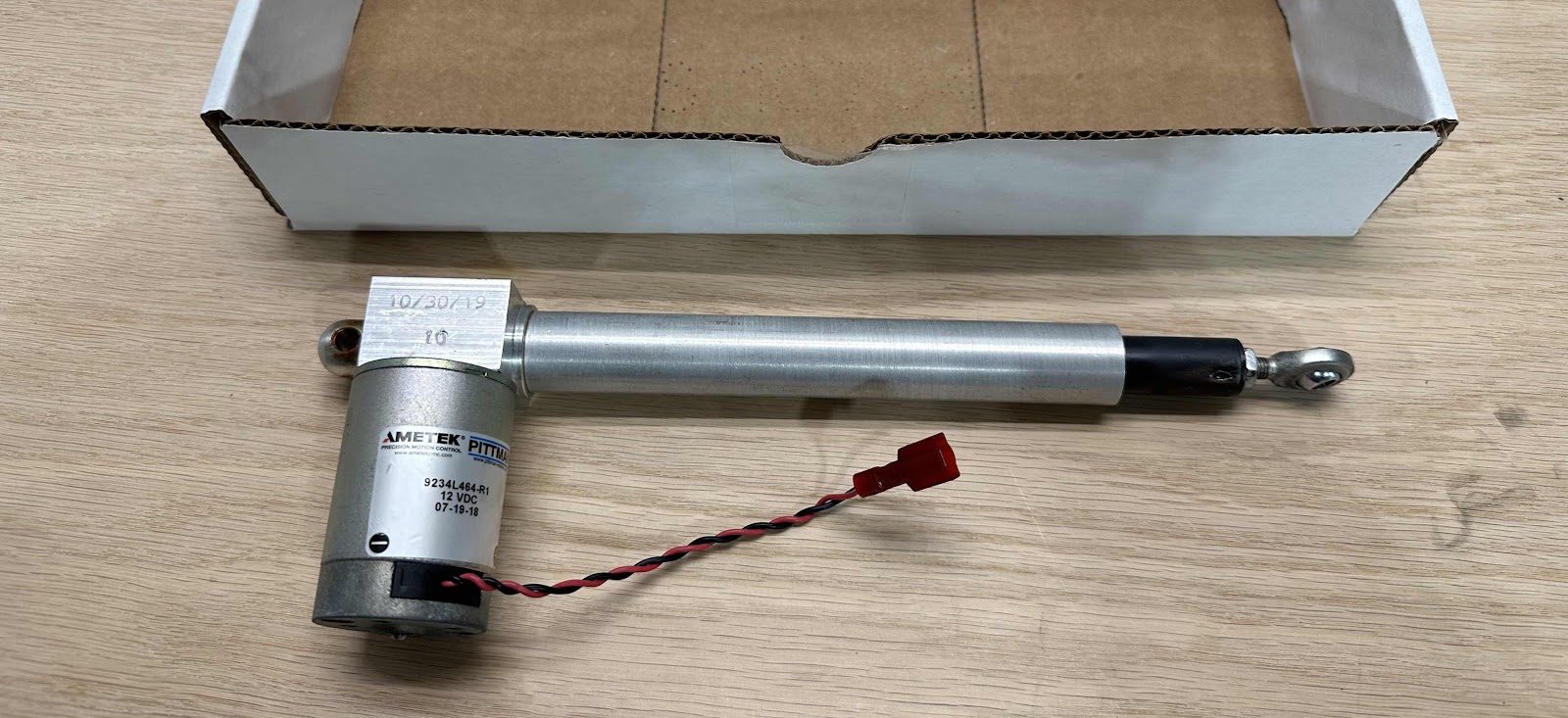
Previously, I completed Section 34 (Flap Actuation System).  In completing that section, I installed the stock Van’s ES 85615-10 Linear Actuator (Flap Motor) as directed in the plans.  Here is what the Flap Motor looked like before I installed it in the plane.


Now, fast forward to Section 54 (Flap Position Sensor) of the build plans.  This section has you install The Ray Allen Company ES MSTS POS-12 Flap Position Sensor.   As the only Post for Section 54 says, I wasn’t the biggest fan of that setup.  (See Section 54).  Like I said, there is nothing wrong with the factory setup, I just wanted something more “all in one” and more robust.

As I also mentioned in Section 54, I began to do some research to see what options existed in the aviation market.  Based on my research, and a recommendation from Aerotronics, I decided on the RV Max Flap Actuator from PH Aviation Services in March of 2022.  This Actuator has internal limits, internal position sensing and is very robust.  This setup does away with the two piece setup (separate flap motor and position sensor), did away with the safety wire that was required to be installed on the factory actuator and combined everything into one robust setup.  That pretty much meet the requirements I was looking for in a replacement flap motor.  I didn’t get any pictures of the actuator prior to installing it, so if you click on the link I provided above, it takes you right to the page.  On that page, it gives you the specs and price for the actuator.

As the PH Aviation Services website says, this is not a drop in replacement for the stock actuator.  So, some minor modifying was required, but was pretty easy to do.  I will use this section to show you the modifications and what it looks like installed.