
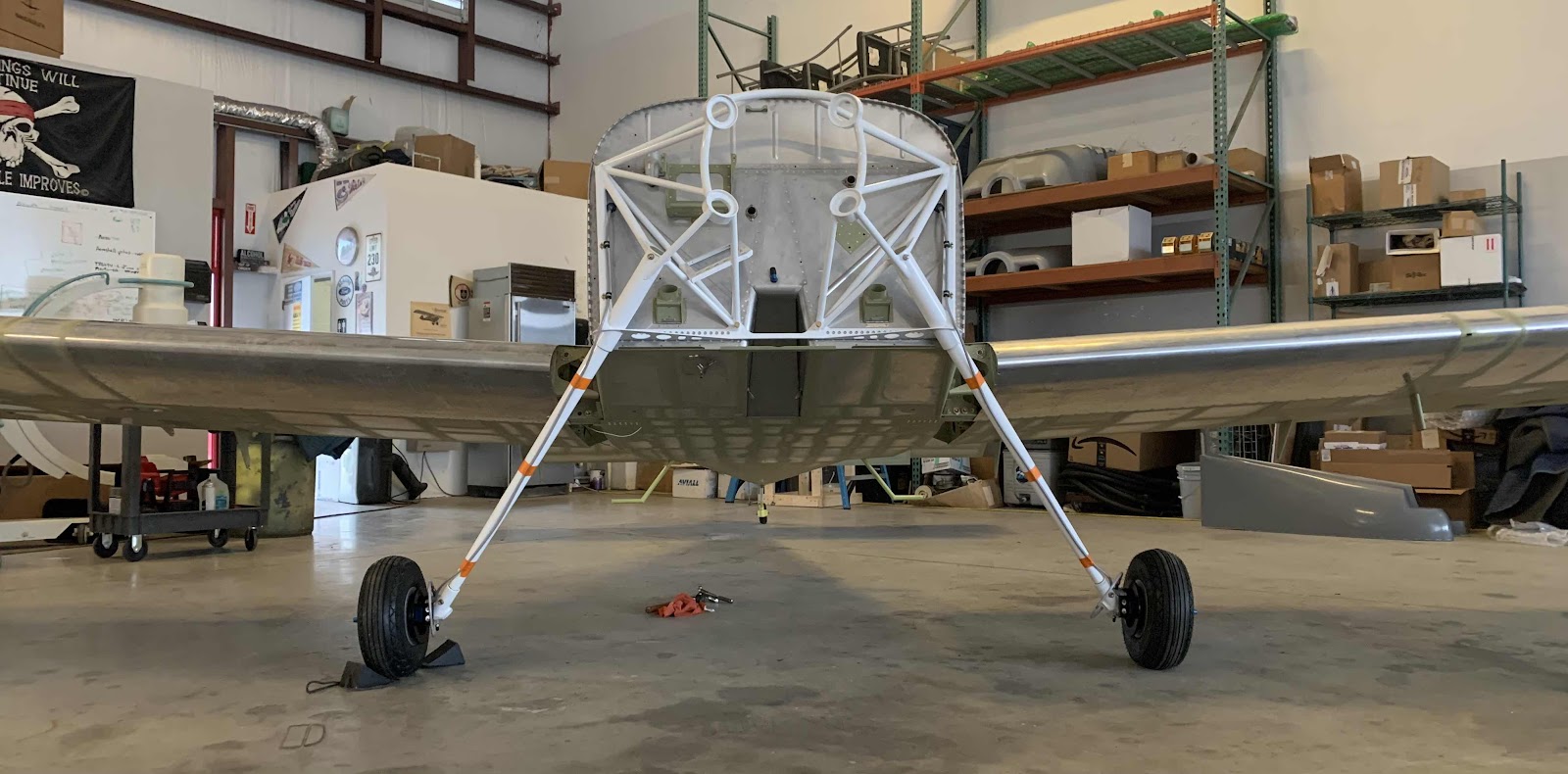
The work and pictures in this post are from September 16, 2021. This is what the engine mount looks like on the plane ready to accept the engine.
To start this section, the ES PC680 Odyssey Battery is installed into the FF-01403 Battery Box (previously installed on the firewall) and secured with the F-01403A Battery Box Angle. Then, the WH-P25 2AWG Ground Strap is installed on the aircraft’s firewall ground, but is left disconnected from the battery negative. Finally, the WH-P769 Starter Relay Power Cable is attached to the battery positive (along with the insulated boot).

This shows the ES 24115 Master Relay (top) and the ES 24021 Starter Solenoid (bottom) attached to the firewall. Also seen here is the WH-K1066 Relay Interconnect Bar attached (with the installed heat shrink) between the two parts.

Page 43-04 of the build plans includes several electrical connections made to the Master Relay and Starter Solenoid. They include: WH-P912 Battery Power Wire, WH-P769 Starter Rely Power Cable, ES Diode Master, ES Diode Starter, WH-P16 Starter Relay to Starter Wire and the WH-P910 Starter Disengage Wire. These two pictures show all of those connections completed per the plans.

