This blog was created to memorialize the building process of my Van's Aircraft RV-14 and to satisfy the requirements for certification in the Experimental Amateur Built Aircraft category. It will also serve as a central location for ME to reference in the future on processes and techniques I used during the build. Additionally, it will allow my family, friends, and other interested builders the opportunity to follow along during my build…..and might be helpful to someone along the way.
I was able to work a little longer session tonight and completed the prep work on seven pieces. Below, are the completed F-01407-L & R Bulkheads, F-01408-L & R Side Frames, and the F-14115 Rudder Cable Bracket.
I Final-Drilled a the #40 nutplate attach holes on the F-1037B and F-1037C Battery Angles. Then, the nutplate attach holes on the battery angles were countersunk to accept AN426AD3 flush rivets. I clamped the angle to the workbench and elevated them by two pieces of 2x4.
In the post for Part 8, I wrote about dimpling and riveting the F-01412A and F-01412B Bulkheads in the wrong direction. As a result, I had to order two new pieces. The two Bulkheads arrived today from Van's and I began the prep work. Here are the Bulkheads right out of the box.....
I completed all the edge work, Match-Drilling, and Final-Drilling as indicated in the plans. Finally, I dimpled all the #30 and #40 holes in the Web and Flanges of both Bulkheads......IN THE CORRECT DIRECTION!!!!! They now join the MANY parts that are ready for Alumiprep, Alodine, and Primer.
I worked another short session tonight, but prepared four more pieces.....small steps forward. I completed all the edge work and dimpling (mostly). There are still eight holes in the Skin Doubler I need to dimple. However, I need to get a reduced diameter 3/32 (#3 rivet) female dimple die. There is a bend on each side of the Doubler that is rather close to the rivet hole. Because this hole is so close, a standard sized die would deform the bend and jack up the piece.
I had a short work session today, but was able to finish the prep work on two more pieces. I completed all the edge work and dimpling on the F-01406B Bulkhead. There will also be 11 nutplates installed on the this Bulkhead. You can see nine locations in this picture.....
.....and the last two nutplates on the tab in this picture.
Here are two shots (forward and aft sides) of the F-01409 Frame. I also completed the edge work and dimpling on this piece.
I have about six or seven parts (minus the Skins) left to prep before Alumiprep, Alodine, and Primer. I plan on clecoing all the parts together (prior to priming) to verify the fit of all the pieces. I'm sure everything will fit just fine.....
Today's session is another one of those....lots of work accomplished, but nothing to really show for it. I spent a vast majority of the session doing edge work on the numerous parts and preparing them for Alumiprep, Alodine, and Akzo Primer. I've tried several different methods to accomplish the edge work, but I kind of just like the old fashioned hand sanding of the parts. Sure, it takes longer (much longer in some instances), but it works for me and I like the results.
Here is the Aft Deck following the edge work and dimpling. The eight holes, right of the big hole in the middle, were dimpled using the pneumatic squeezer with a 3" yoke.....very quick and easy.
If you will remember back to Part 3, I was not very please with my fabrication work on the F-01411D Horizontal Stabilizer Attach Bar Support Angle. So, I ordered another one from Van's following the Fourth of July weekend. The replacement part arrived in the mail a couple of days ago and here is the piece being fitted to the Aft Deck. I have the left and right edges fitted (mostly) to the sides of the Aft Deck. Now, I need to continue the fabrication work as outlined in the plans. I will post a picture of the final product when it's completed.
Yesterday, I posted a picture of the large Side Frame. Here is the small Side Frame clecoed together with the Rudder Cable Bracket.
Here are the two Side Frames together.
In Part 7, I primed several parts with Akzo Primer. The primer was allowed to dry overnight and I started to rivet the parts together.
NOW.....
I got a little pouty when I noticed what I did.....can you tell? Maybe not! The manufactured heads of the rivets should be on the AFT side of the assembly. So, I made one mistake (dimpled the wrong direction) which lead to the second mistake (installing the rivets in the wrong direction). The correct way would allow a smooth, unobstructed mounting surface for the Vertical Stabilizers Rear Spar. My bonehead work.....well, you can't do it! So, Van's.....can you please send me some more parts???
I suspect I could remove the rivets, separate the parts, and dimple the dimple the opposite direction.....I suspect. However, it would not be right. So, I ordered two new parts.
Here.....I did it correctly and put the manufactured heads on the aft side of the assembly. This is the F-01411-A & -B Bulkheads and F-01411C Horizontal Stabilizer Attach Bars riveted with AN470AD4-7 universal rivets.
I was able to put in a full day on the Aft Fuselage today. Yesterday, I completed all the prep work (edge work, dimpling, drilling, etc) on the parts in the picture below. Today, I completed the Alumiprep, Alodine, and Priming. With the exception of the Rudder Stops, I will rivet these parts together tomorrow.
While the primer was drying, I removed the blue protective plastic on the parts below and started some of the prep work. I began the edge work and the bottom holes on the Horizontal Stabilizer Attach Bars were Final-Drilled to 1/4.
I also did a test fit of the pieces.....they fit perfectly!
I removed the blue protective plastic and test fit one of the two Side Frames. The one in the picture is the larger of the two. The Rudder Cable Bracket will be installed on the smaller of the two Side Frames. I will test fit the smaller Frame tomorrow and start ALL the prep work on ALL of these pieces.
I started tonight's session by doing the prep work on the F-01411C Horizontal Stabilizer Attachment Bars and the F-01411A and F-01411B Bulkheads. I completed the edge work on all four pieces, the dimpling on the Bulkheads, and Final-Drilled 1/4 the bottom holes of the Attachment Bars (only done on the tailwheel models). Van's also provides two options for attaching the F-14112 Plate Covers (installed later in the build).....round head or flush head screws. I've decided to use the flush screws, so the four #27 holes (where nutplates will be installed) in the flanges of the "B" Bulkhead were dimpled with #6 screw dimple dies.
Now, the four pieces were clecoed together and the 30 holes common to the Attachment Bars and the Bulkheads were Final-Drilled #30.
I completed the Alumiprep and Alodine process on the two Bulkheads and hung them up to dry for the night. I will pickup here during the next work session.
Tonight's session focused on edge work.....lots of it!! I completed all the required edge work on the numerous pieces shown in the photos below. Not very exciting work, but definitely necessary work. I tried a combination of several different methods to see which one I liked the best. I tried simple hand sanding, hand sanding with the sandpaper wrapped around a piece of wood, a dremel tool with a sandpaper attachment, and a 2" Scotch Brite wheel. I liked them all, but the Dremel tool seemed the easiest to work with. I suspect I'll continue using several different methods over the course of the build. Anyway......
Tonight, I fabricated the left and right Rudder Stops. The F-14113-R and -L Stops had to be separated from one piece of aluminum angle. The first picture shows the actual angle that I will use to fabricate the Stops. The second picture is the excerpt from the plans that illustrates what the Stops should look like after completion.
First, I used my bandsaw to cut the angle into two pieces down the centerline.
Next, the shape of the Rudder Stops had to be cut from each piece of angle. Here is an excerpt from the plans that illistrates the measurements used to mark each of the pieces. Then, I used the bandsaw again to cut the aluminum as marked.
After cutting, filing, and sanding the pieces, here are two different views of the completed left and right Rudder Stops. The last step is to machine countersink the four holes on each Stop for the head of an AN426AD4 rivet.
I started work tonight with the Horizontal Stabilizer Attachment Bars (x2). The plans stated that these Bars may be bowed slightly due to the punching operation used during their manufacture and must be removed prior to installation. The plans excerpt below shows the Van's recommend procedure for straightening the Bars. This process can be repeated to straighten any other thick (.125 or thicker) part which has been bowed during manufacturing.
You start by clamping the Bar into a padded vice (wood, aluminum, etc) near one end. Pre-load the free end of the Bar in the direction required to be straightened. Then, you take a rubber mallet and strike the bar one time near the vice. Next, you slide the bar further into the vice and repeat the process until the bar is straightened to within 1/16 along the entire length. I used this process to straighten both bars.
The next step in the plans is to fabricate the Horizontal Stabilizer Attach Bar Support Angle. I worked on this piece for awhile, but was not happy with he results. So, I'm going to order a replacement from Van's following the 4th of July weekend.
I moved on to clecoing the F-01412A and F-01412B Bulkheads to the Vertical Stabilizer. The picture below shows the Bulkheads clecoed to the Vertical Stabilizer using the two locator holes.
The two holes circled below were Match-Drilled to #40. The large system hole in the center was Final-Drilled to 17/64.
The picture below is of the Vertical Stabilizer on the opposite side of the Bulkheads. The two circles on the right are the #40 holes with the clecos installed. The system hole is on the opposite bracket.
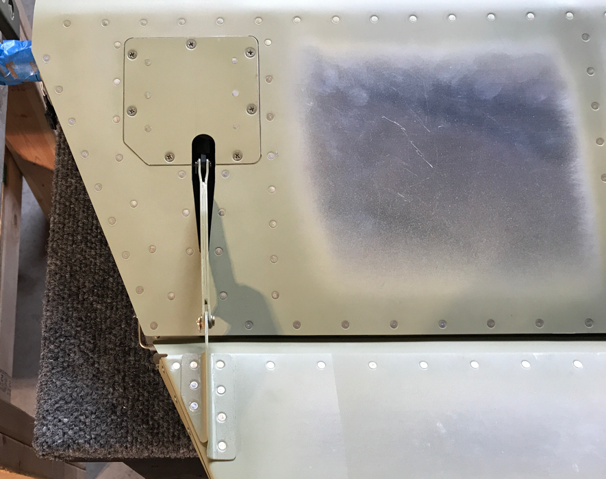
The Elevator is COMPLETE! During tonight's session, I only had to install the counterweights and Trim Tab Servo. Here is the Trim Tab Servo installed on the Left Elevator Bottom Skin with the seven screws.
These pictures show the counterweights attached to the Right Elevator.