Friday, March 20, 2020

Fuselage, Upper FWD Fuselage (Part 1)


Moving on to Section 35:  Upper FWD Fuselage.  The first two parts to get attention in this section are the F-01456-L & -R FWD Fuse Ribs.  Here they are as they came from Van’s with the blue plastic.....

.....and here are the two Ribs after being prepared.  All the edges were cleaned, all the holes were deburred, and the appropriate #40 holes were dimpled.  

Next, the F-01456A-L &- R were prepared.  Again, here is how the part(s) come from Van’s.....

.....and after being separated, edges cleaned and holes deburred.  None of the holes on these two parts needed to be dimpled.

Lastly, the two F-01456B Gas Spring Brackets had their edges cleaned and holes deburred.

All six parts are now ready to be treated with Alumiprep, Alodine and Akzo primer......tomorrow.


Thursday, March 19, 2020

Fuselage, Flap Actuation System (Part 1)


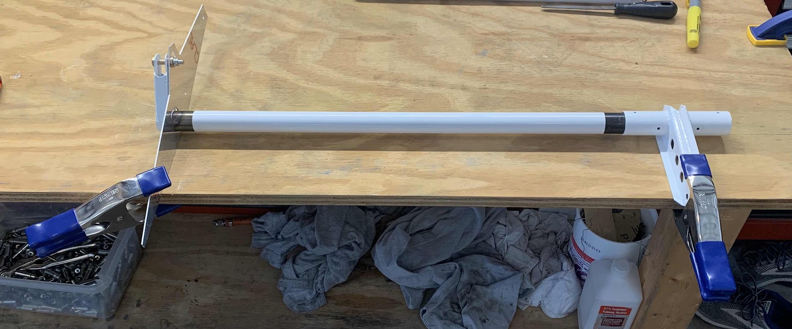
Section 34:  Flap Actuation System only three pages in the plans and should go relatively quickly.  A couple of things are going on in the picture below.  On the right, the first step is to clamp the WD-1013A Flap Crank to the table.  Next, the CS-00010-L Flap Torque Arm is inserted into the W-00026 Alignment Template and secured with the appropriate hardware.  Lastly, the Template is also clamped to the table.  

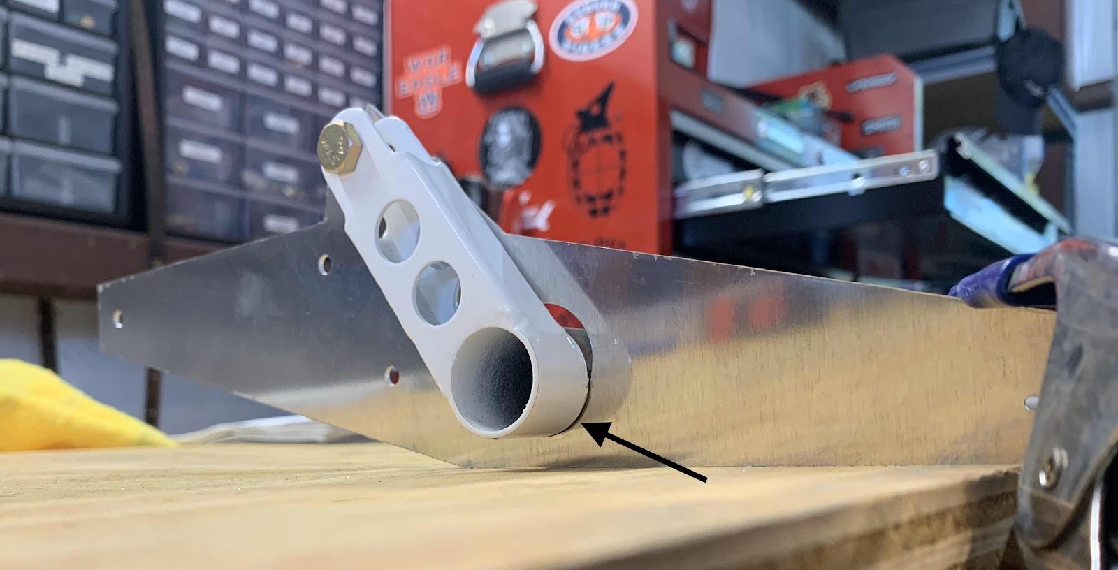
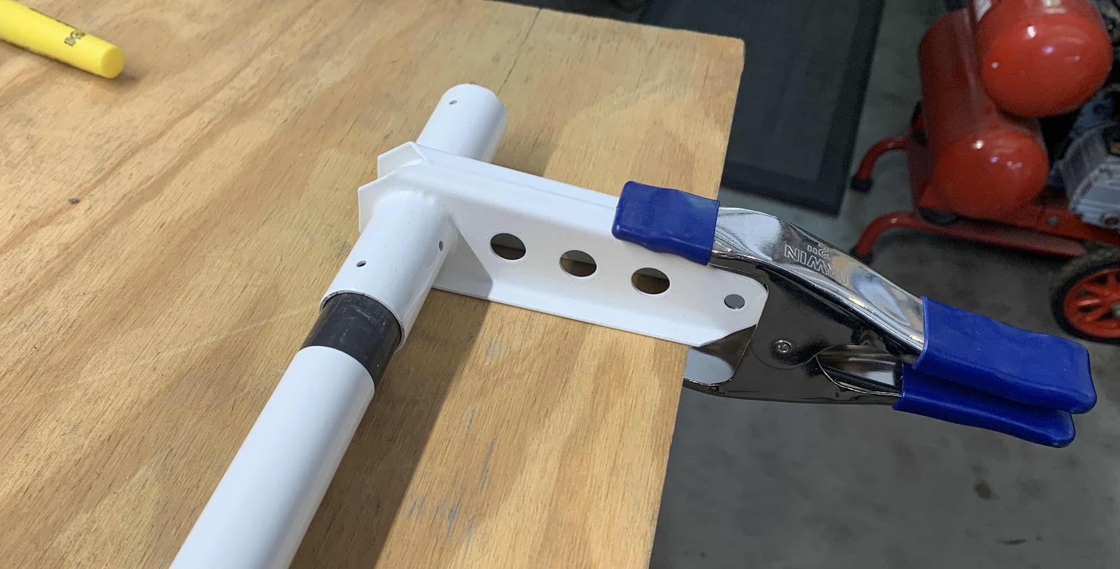
Here is a closer look at the left Flap Torque Arm inserted through the Alignment Template and secured with the appropriate hardware. 

The plans emphasize to make sure the bottom edge of the Flap Torque Arm (arrow) has full contact with the bottom radius of the Template.  Initially, when I tighten the hardware, the bottom of the Torque Arm would rotate slightly and not have full contact.

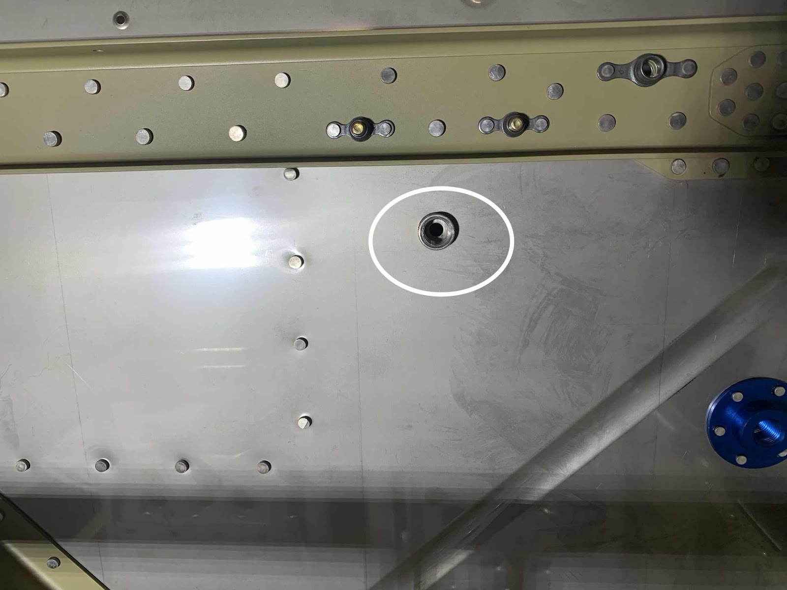
I investigated as to why.  In the picture below, I circled the hole in the Template the hardware gets installed through.  If you look closely, on the right side of the hole is a “burr”.....there WAS one on the left side also.  I lightly filed the burr off the left side which resulted in full contact of the Torque Arm when the hardware was tightened....problem solved.

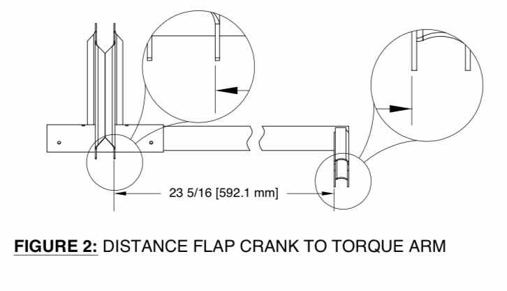
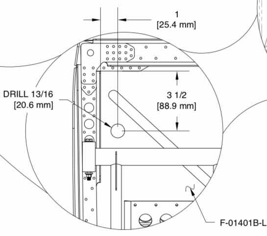
The plans state to position the Flap Torque Arm laterally 23 5/16” from the Flap Crank as shown below.

After measuring the correct distance, I clamped everything into place.  As you can see, the Torque Arm doesn’t get installed in the Flap Crank all the way up to the powder coat.  Once this accomplished, the top hole on the Flap Crank is match-drilled #30 into the Torque Arm.  A cleco was inserted into that hole and the hole on the opposite side is also match-drilled #30.  The assembly was unclamped from the table and the remaining two holes were also match-drilled #30.

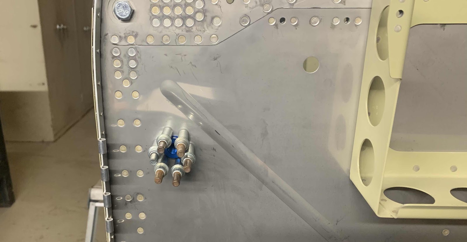
This picture shows all four #30 match-drilled holes from the Flap Crank through the Torque Arm.  Lastly, the holes were match-drilled #12 all the way through the holes on both sides of the Flap Crank and Torque Arm.  The parts are held together with two AN3-14A bolts.

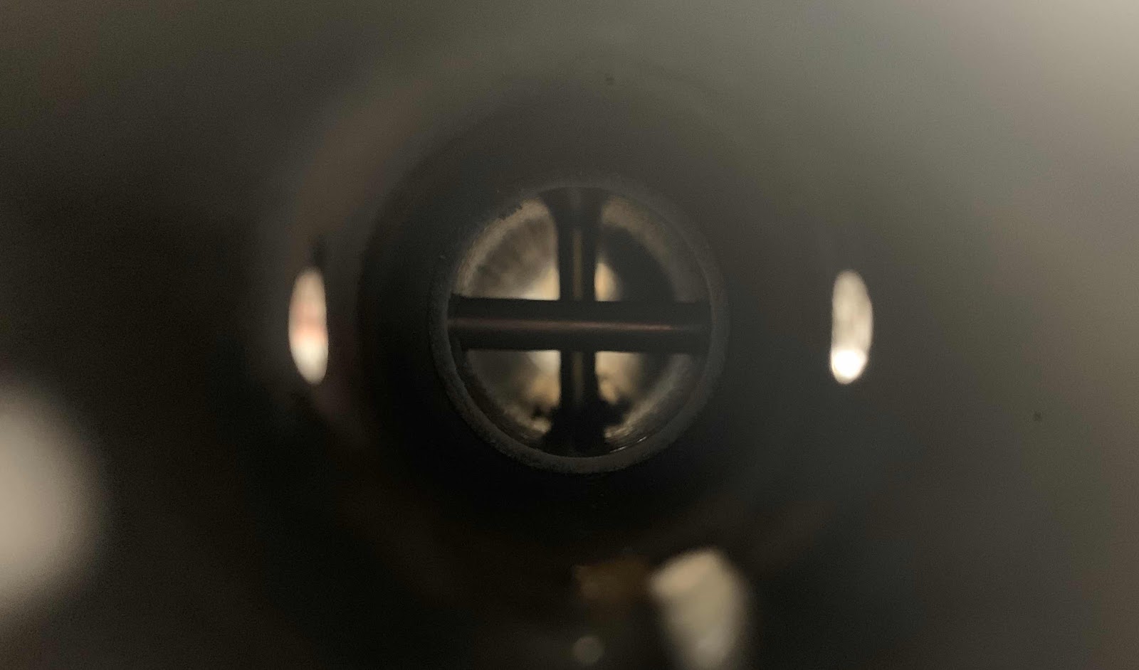
I thought this was a cool picture.  It is looking down the Torque Arm where the bolts pass through the two parts.  This completes the preparation work for the left Flap Torque Arm.  The right Torque Arm was prepared exactly the same way.  I also primed inside the both Torque Arms and Flap Crank prior to assembly.

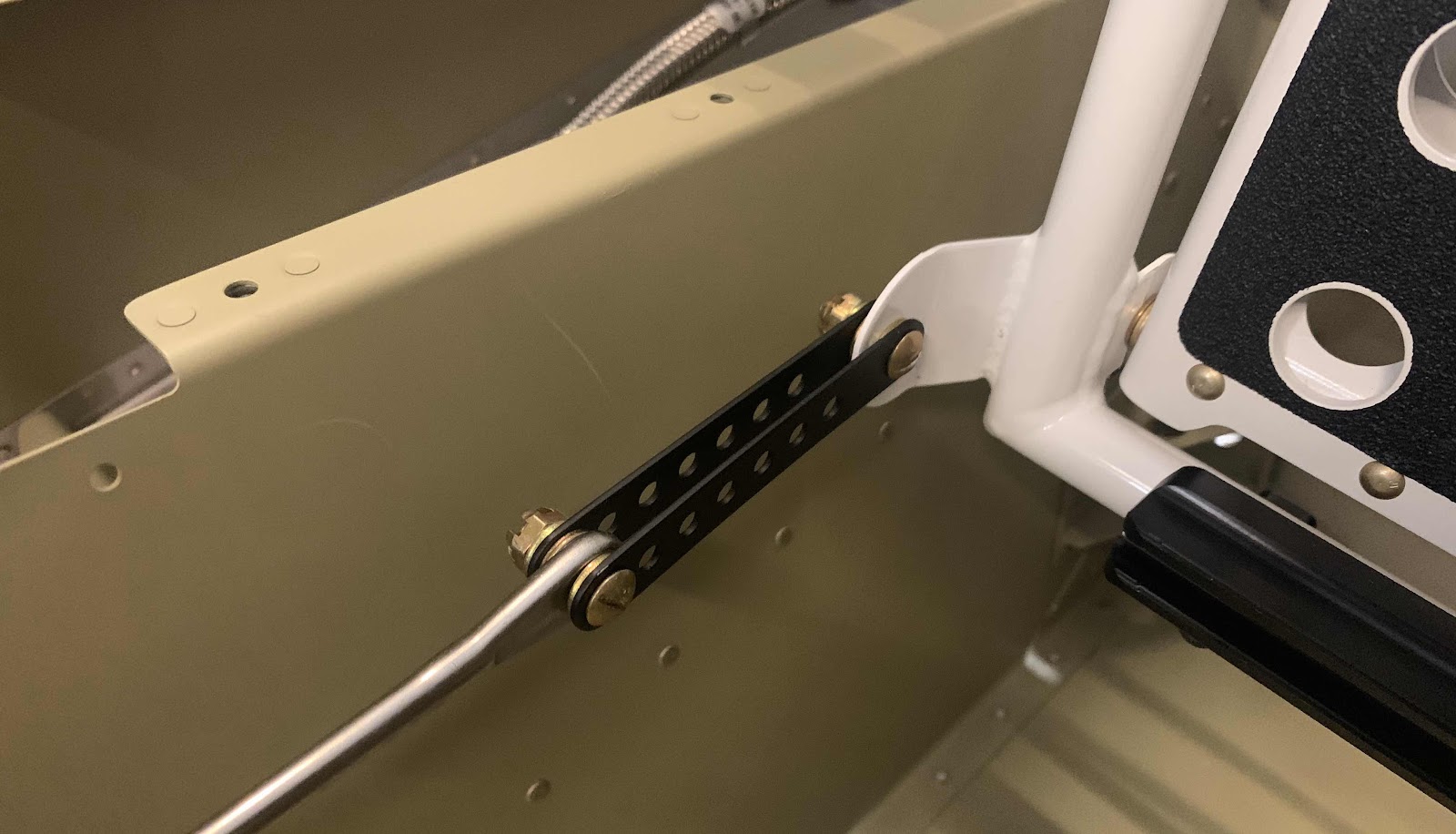
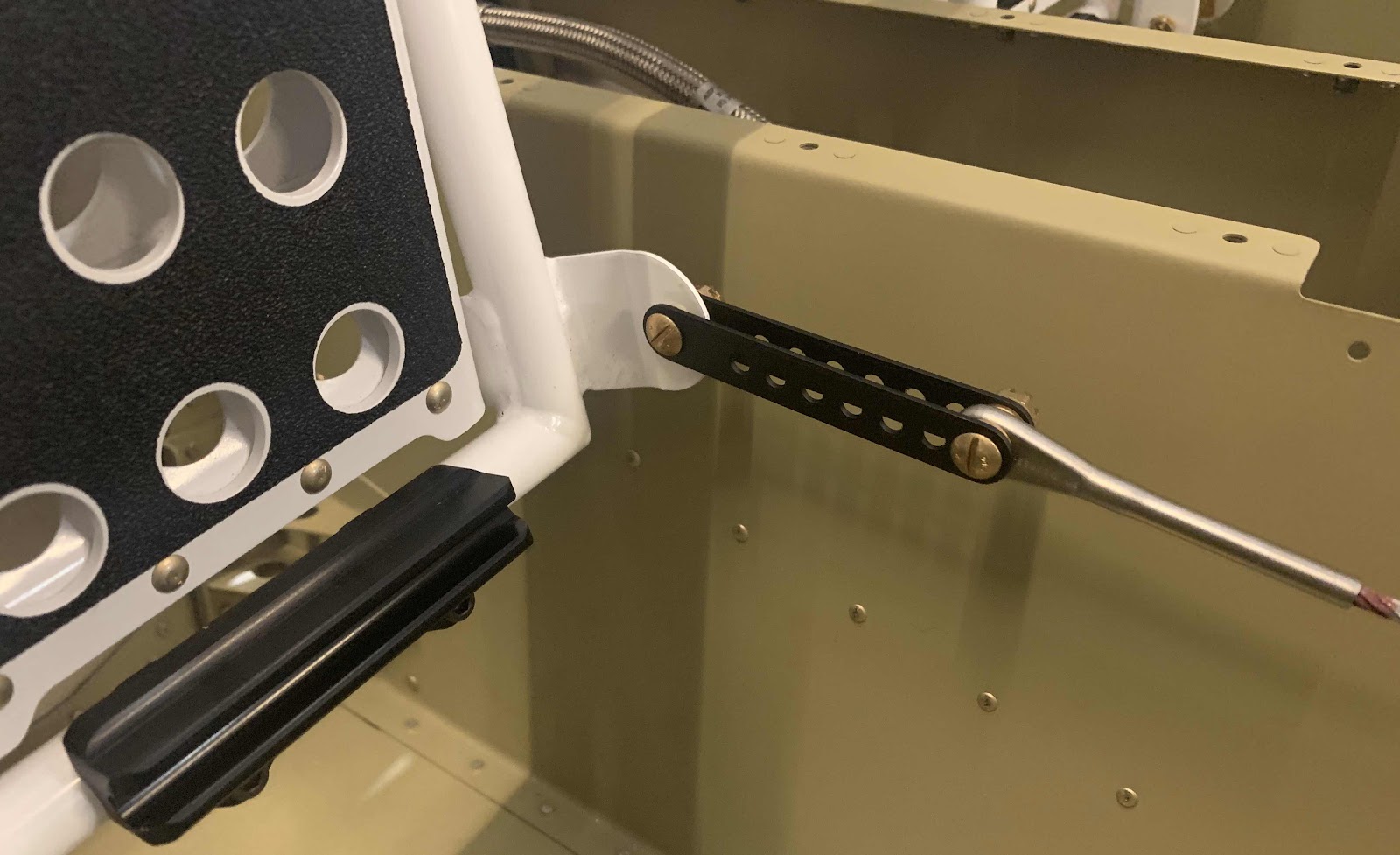
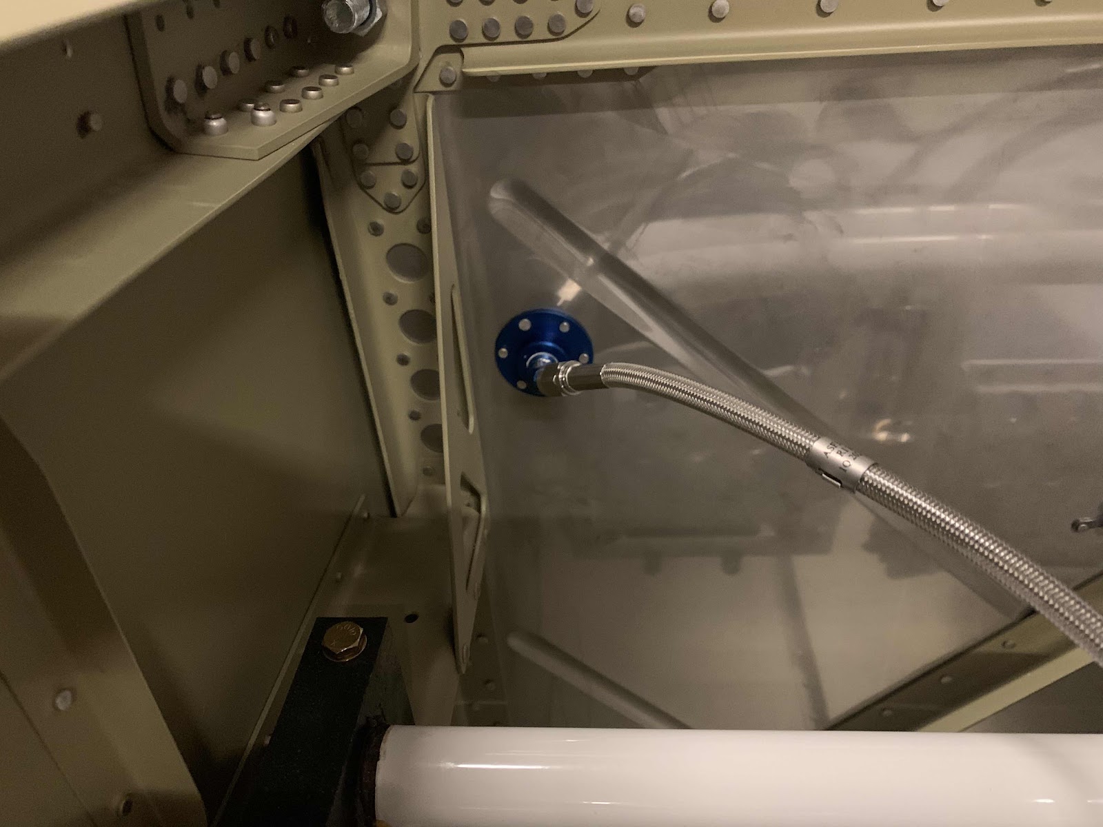
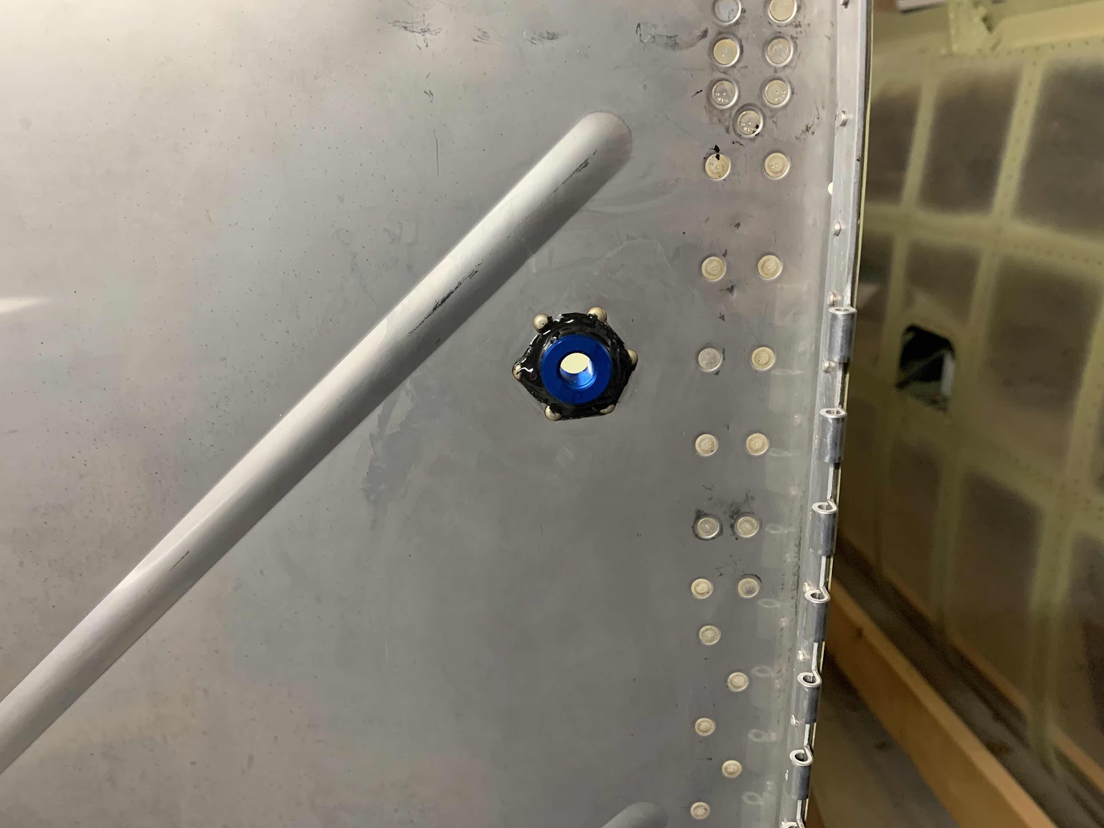
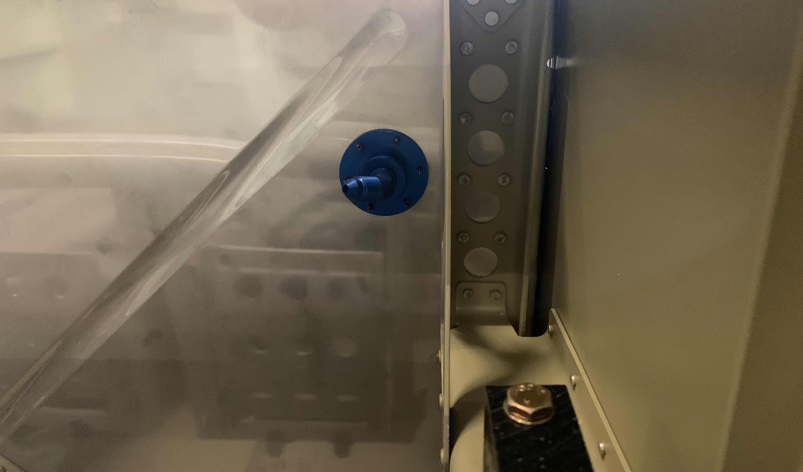
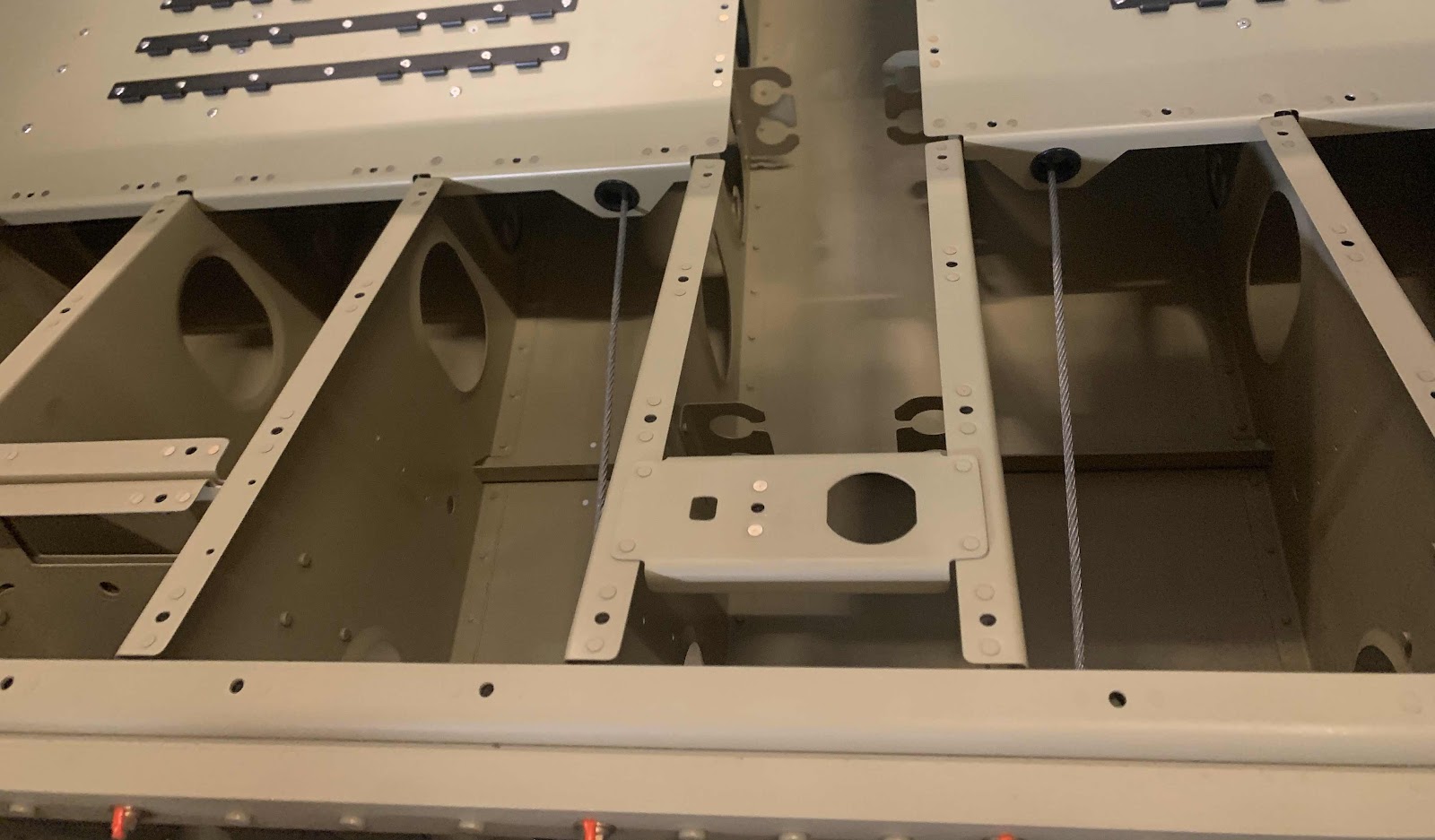
Each of the Torque Arms were then inserted into the F-1030 Outboard Bushing into the Inboard Bushing.  This is the right side.....

.....and the left side.  Prior to being inserted into the Bushings, the areas on each Torque Arm that was not powder coated were coated with wheel bearing grease.

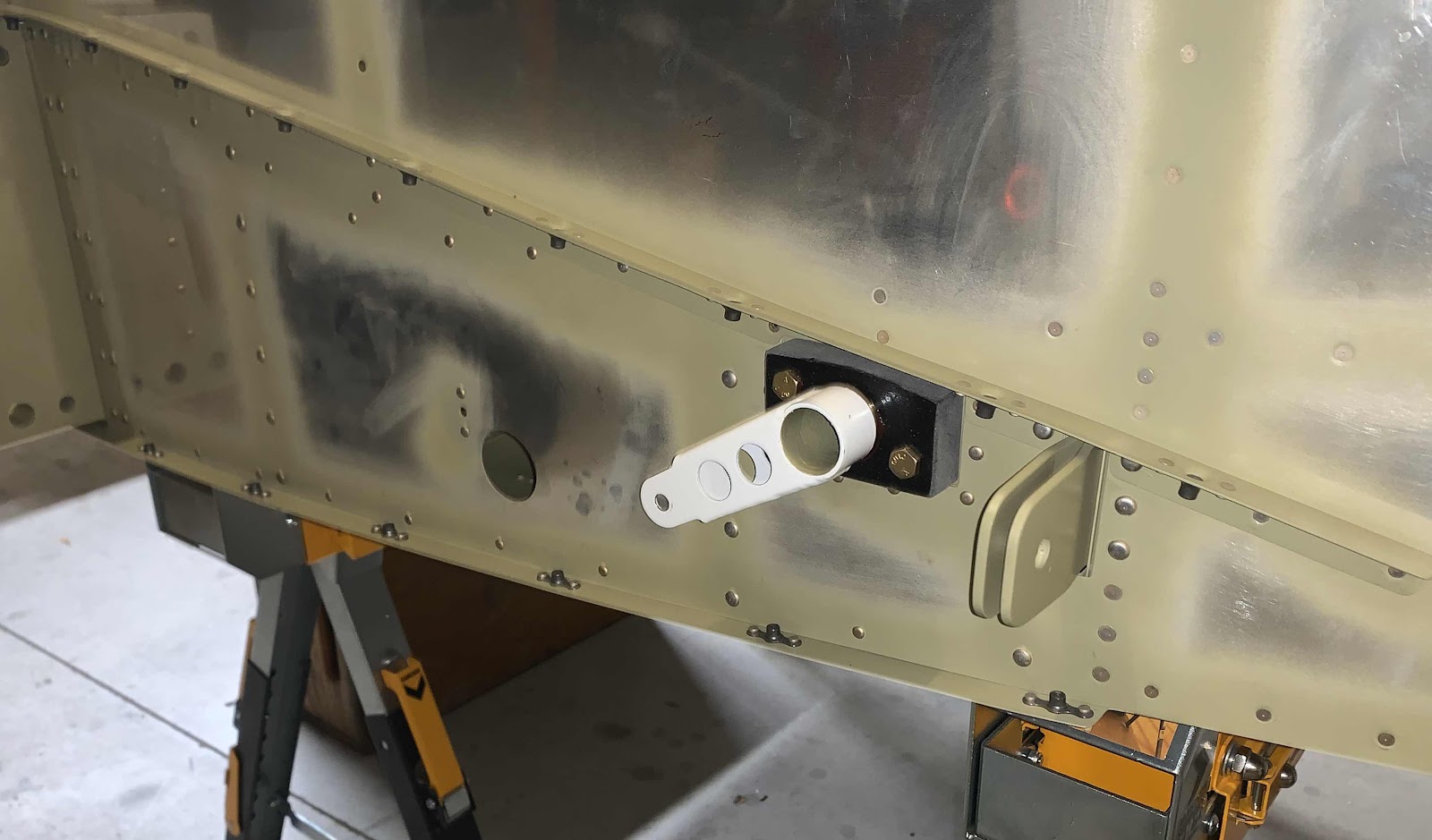
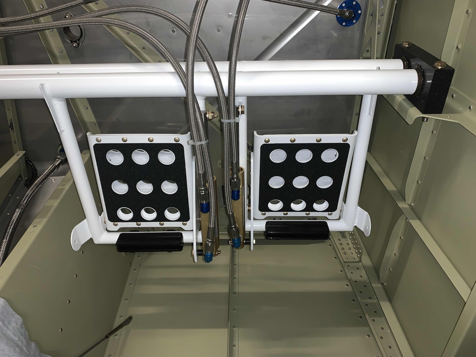
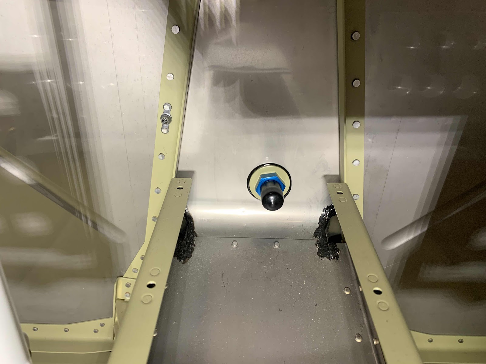
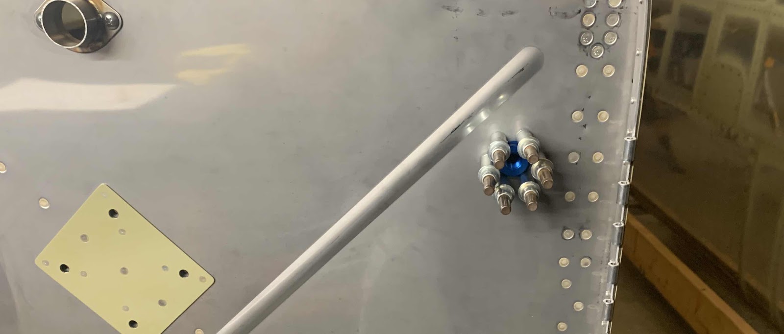
Both Torque Arms meet in the middle and get bolted to the Flap Crank.  The Assembly was hold together using four AN3-14A bolts.  Here is one view showing the two inside bolts (complete with torque seal).....

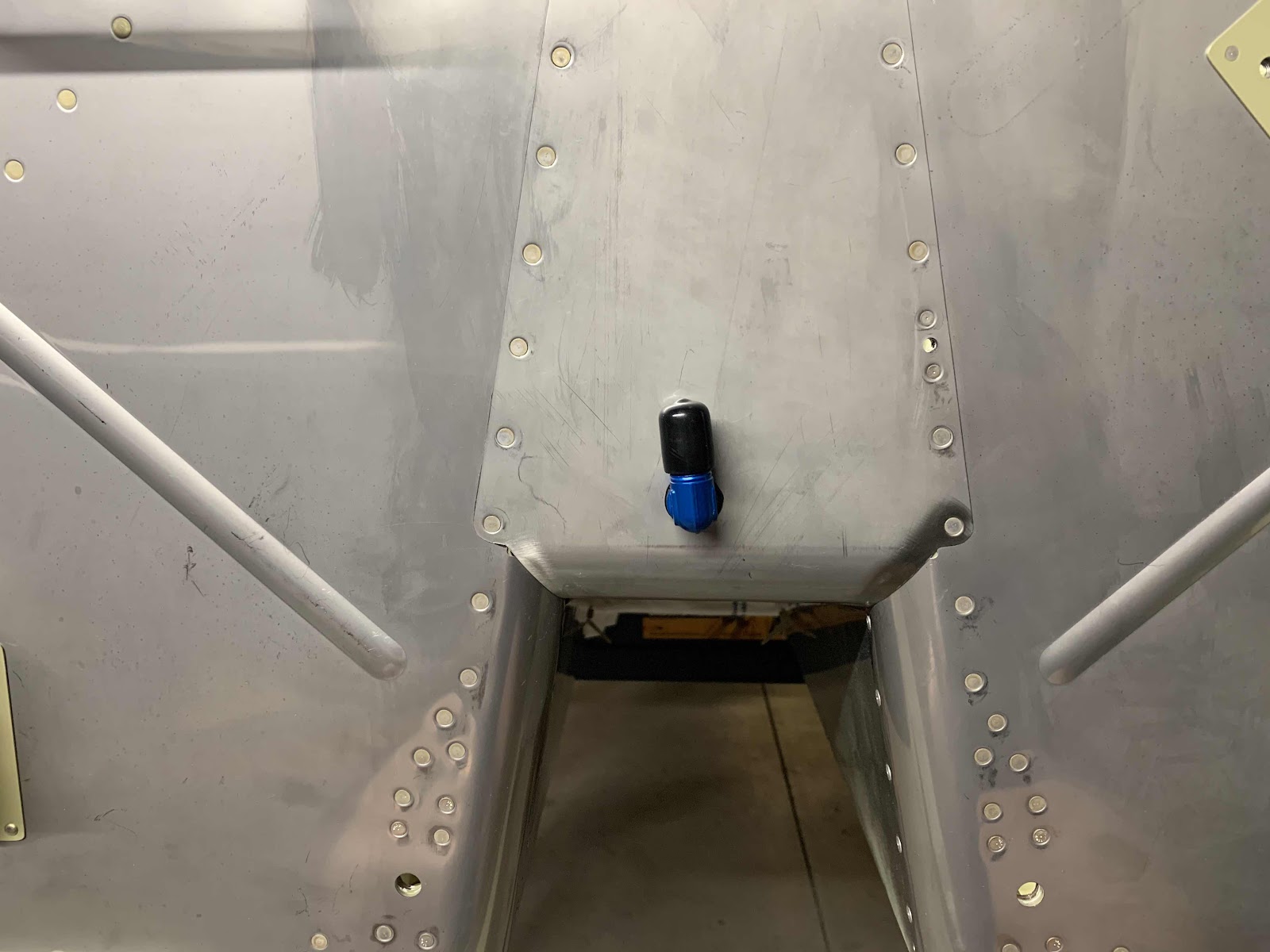
.....and the two outside bolts.

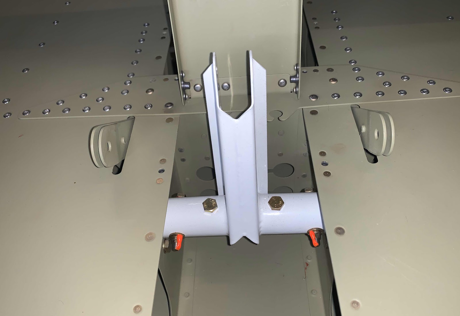
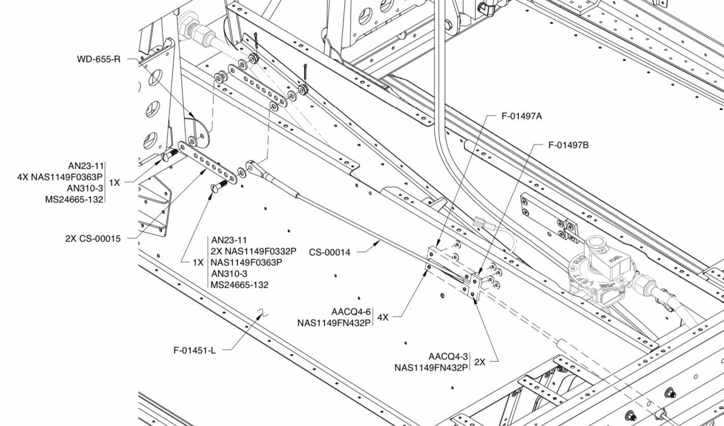
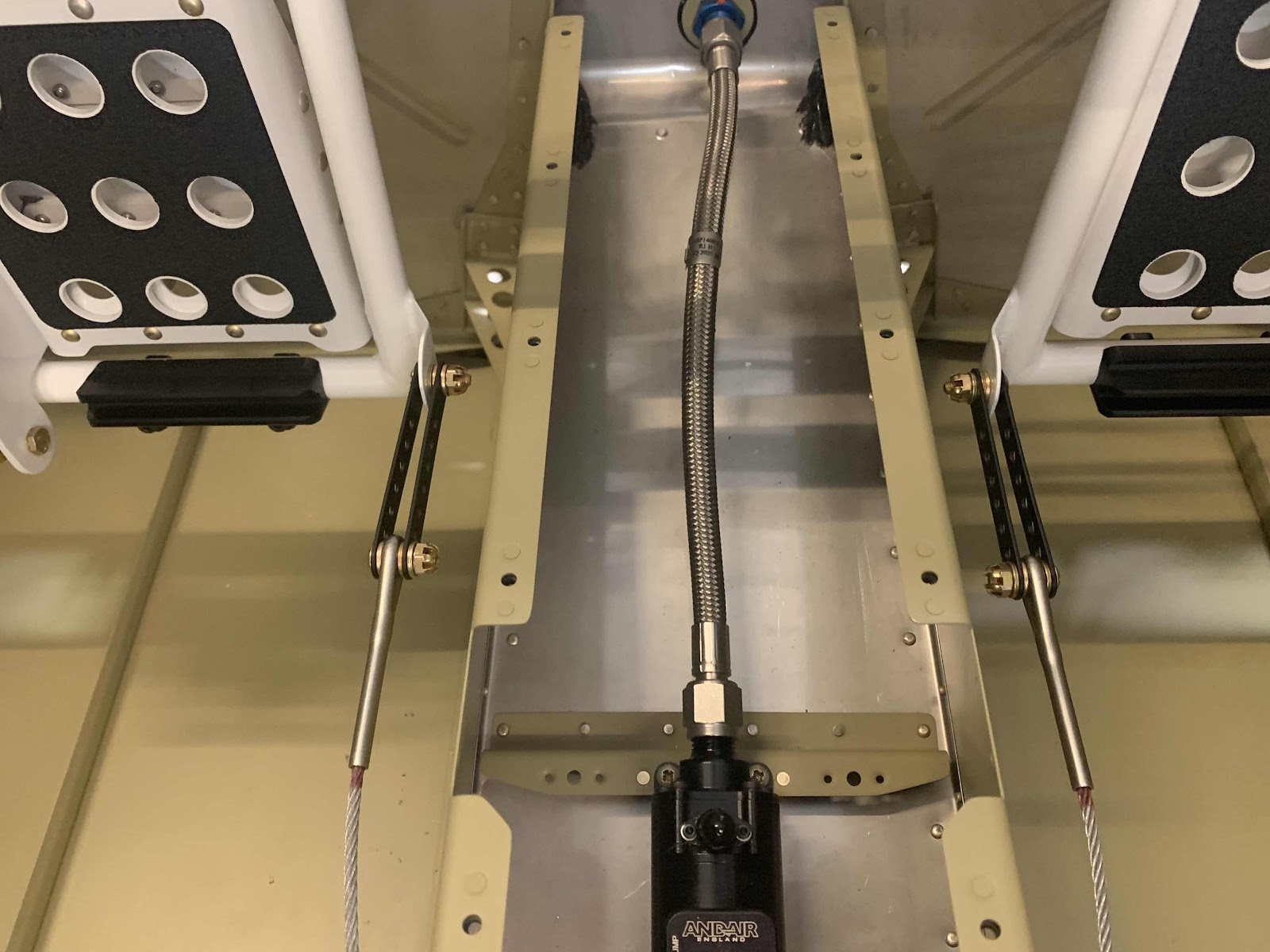
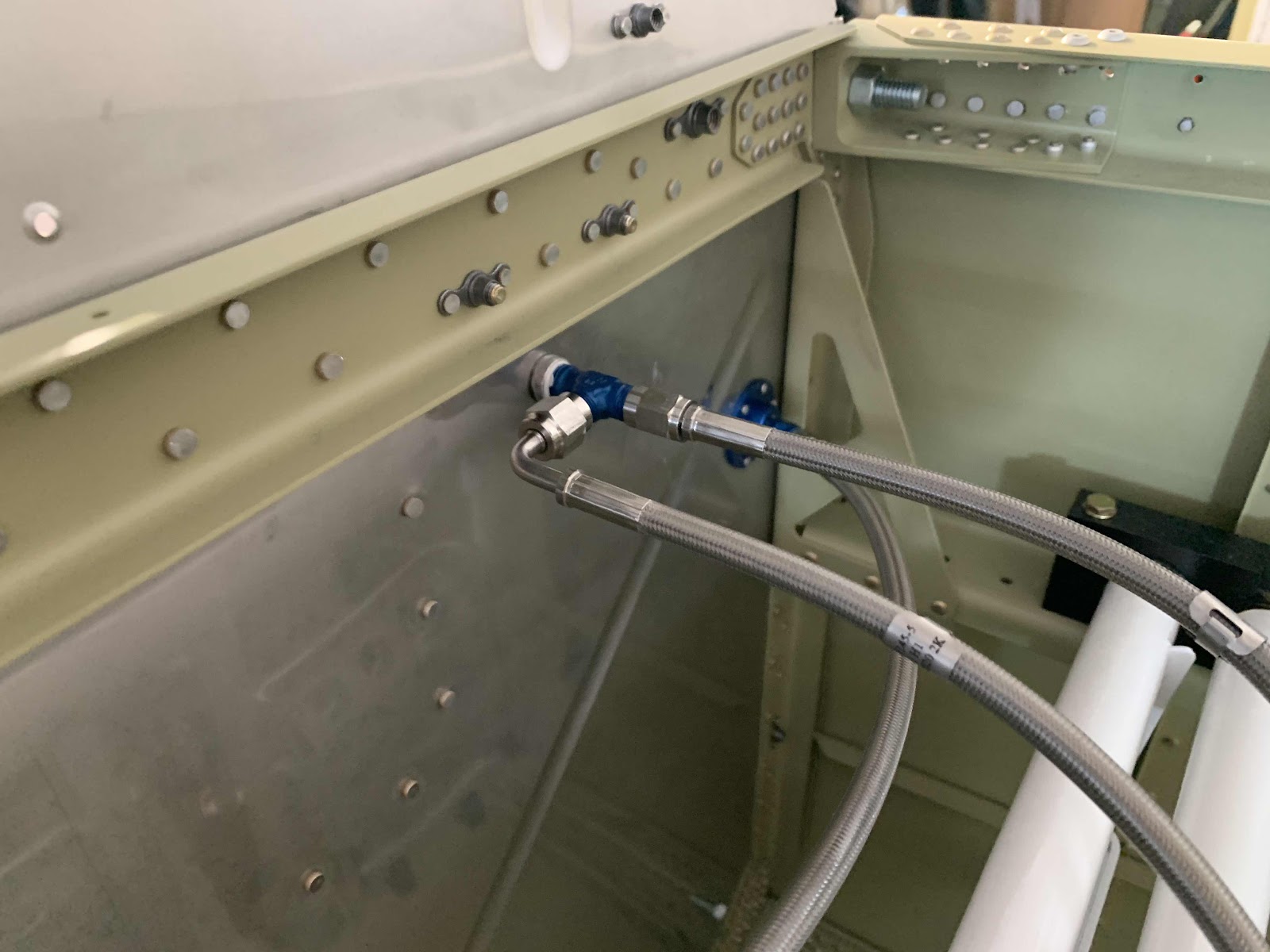
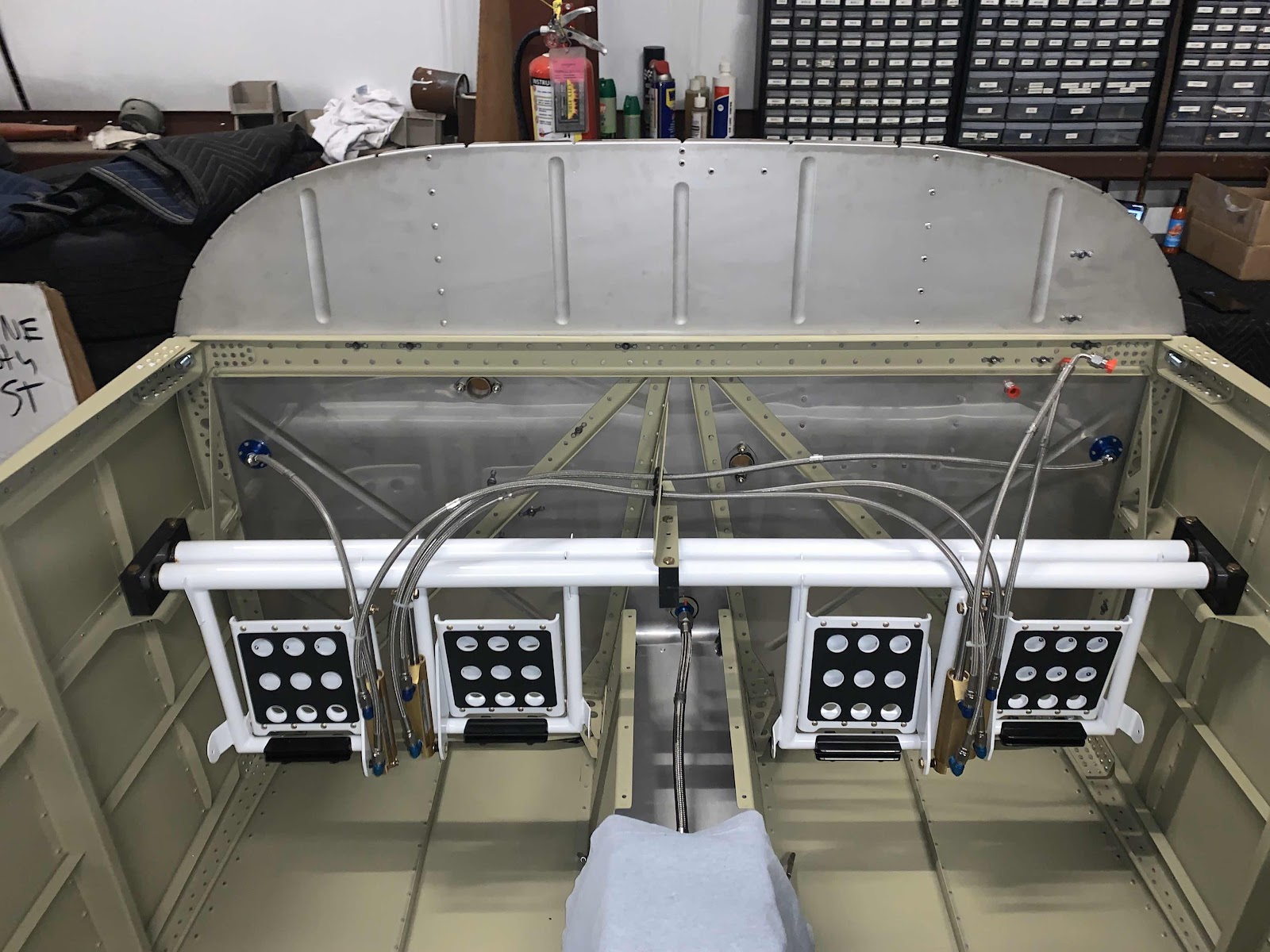
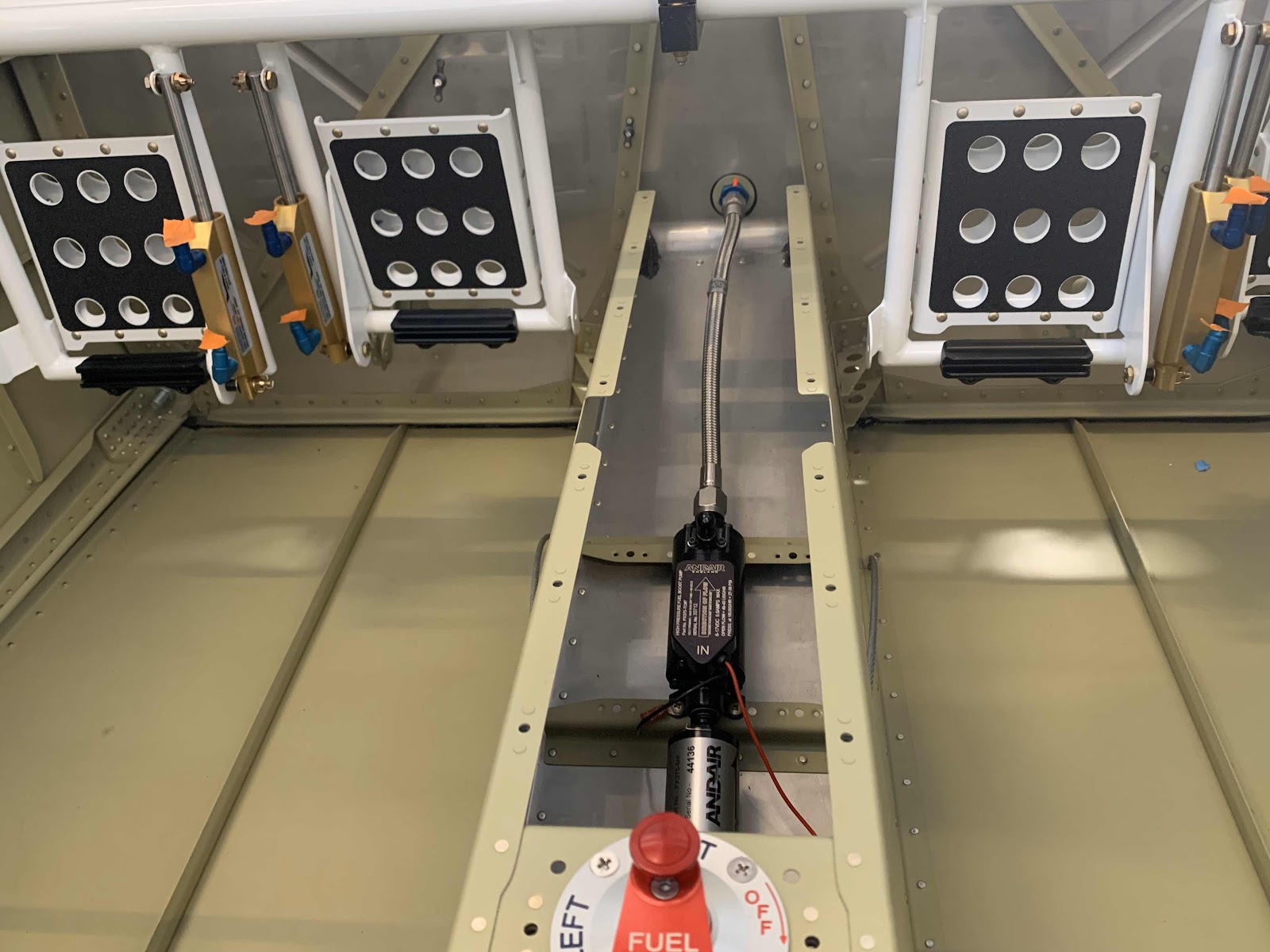
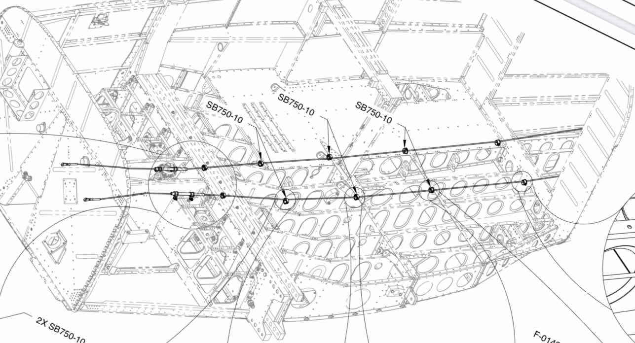
This is an overview of the Flap Crank position and location within the cabin.

Monday, March 16, 2020

Fuselage, Rudder and Brake System (Part 14)

In Part 13, the four Cable Links were Akzo primed and top coated with flat black paint.  Now, I will install them on the plane.  Here is what the install looks like from the plans and shows the associated hardware.

Here is my completed install of the Cable Links on the right (co-pilot) side....

.....and the left (pilot) side.

Lastly, here is an overview shot containing both installed Cable Links.

The Rudder Cables are currently connected to the first hole of the Cable Links for reference at this point.  I will adjust them in the future (if necessary) when the Rudder Cables are connect to the actual Rudder.

Section Complete

Sunday, March 15, 2020

Fuselage, Rudder and Brake System (Part 13)

I completed all of the Brake Hose installation in Part 12.....with the exception of the AN826-3D Tee.  In the picture below, the blue Tee is final installed with all three connectors.  Initially, the Tee was installed into the nipple of the Brake Fluid Reservoir that passes through the Firewall.  Then, the two remaining Brake Hoses were installed on the Tee.

Here is an additional view from the other side.  That completes the Brake Hose installation!

These are the CS-00015 Cable Links that originally came from Van’s when I ordered the Fuselage Kit.  This is what the Florida air does to metal....pretty quickly.  I decided not to try and clean these and just ordered a new part from Van’s.  So, the Cable Links in the picture below were put in the scrap pile.

After I got the new part from Van’s, I separated and cleaned them up (shown below).  Then, I Akzo primed and top coated them with flat black paint.  I will show the completed Links in the next session when I install them in the plane.

The next step was to install the two F-01497A (large) and F-01497B (small) Cable Guides.  In the picture below, you can see two angles of the Cable Guides.  The large Guides are installed on the aft side with AACQ4-6 rivets and the small ones on the forward side with AACQ4-3 rivets.  You can also see how the Rudder Cables route between the two Cable Guides.  This view is from the right (copilot) side looking left (pilot) side.....

.....and the left (pilot) side looking right (copilot) side. 

I’ll connect the Cable Links during the next session and complete this section.

Install Complete

Wednesday, March 11, 2020

Fuselage, Rudder and Brake System (Part 12)

As I mentioned in a previous post, it’s time to talk more about the Cabin Brake System from Aircraft Specialty.  The picture below shows the completed install of the Stainless Braided Brake Hose kit (minus the AN826-3D Tee installed in the top right corner on the Brake Fluid Reservoir.....more on that later).  The hoses are very high quality, covered with a clear abrasion covering and have a 10 year warranty.  I used the plans from this section of the plans and the guidance from the Aircraft Specialty website for the install. 

This picture shows the hoses final installed to the four -3 size 90 degree AN fittings (AN822 Elbows) on the two Brake Master Cylinders on the right (co-pilot) side. I used this guide from the Aircraft Specialty website to torque the hoses to the fittings.

This is the location where the Brake Hoses pass through the F-14104 Support Angle.  Now, the hoses that come with the kit from Van’s are smaller in diameter than the ones from the Aircraft Specialty kit.  As a result, only two hoses can pass through the hole on the right of the Support Angle (all three of the Van’s hoses are routed through this hole).  So, I had to route the third hose (on the left) through an additional hole in the Support Angle.  The hole was actually too small for the connector on the Brake Hose to pass through, so I had to enlarge the hole to 1/2” with a step drill.  Once all that was completed, I installed a rubber grommet in each hole to complete the pass through.

This shows the hoses final installed to the other four -3 size 90 degree AN fittings (AN822 Elbows) on the two Brake Master Cylinders on the left (pilot) side.

In the center of this picture, you can see the blue Flanged Coupling installed on the right (co-pilot) side.  The Brake Hose is final attached to it with an AN823 45 degree elbow.....

.....and installed the same way on the left (pilot) side.

As I mentioned at the beginning of the post, all of the Cabin Brake Hoses have been completely installed.....minus the AN826-3D Tee fitting.  I will install this fitting during the next work session.  This Tee fitting will be installed between the three connectors shown in the picture below.  So, for now.....this work session is complete.

Fuselage, Fuel System (Part 6)

Tonight, was the last work session for the Section 31:  Fuel System.  

I let the proseal from Part 5 dry overnight and installed the last fuel line hose from the Electric Fuel Pump to the Firewall as shown below.  This hose was also part of the RV-14 Cabin Fuel Line package I purchased from Aircraft Specialty.

Section Complete

Tuesday, March 10, 2020

Fuselage, Fuel System (Part 5)

Tonight’s portion of the work session focusing on the Fuel System went relatively quickly.  

I have been putting off this step because I didn’t have any proseal.  Well, guess what?.....I got some proseal.  In the center of the picture below, you can see the AN833-6D Elbow Fitting (it has a black cap on it) inserted through the Firewall.  Then, you have the blue AN924-6D nut and the green AN SPACER 6D.  To complete the installed proseal had to be installed between the AN SPACER and the Firewall.

To do this, I put the center hole of the AN SPACER around my finger and applied the proseal on the side of the AN SPACER that will rest against the Firewall (after sanding off the primer that is).  Next, I installed the Elbow fitting through the hole in the Firewall, slid on the AN SPACER, smashed it against the Firewall, and installed the blue nut.  As the nut was tightened, the proseal oozed out around the AN SPACER.....the proseal Gods were smiling down on me with this one and the proseal looks pretty damn good!

Here is the finished product.....cabin side.....

.....engine side.

Fuselage, Rudder and Brake System (Part 11)

In Part 10, I drilled the two 13/16” holes in the Firewall and match-drilled the six holes in the flanges for the two FLF-00010 Flanged Couplings.  Tonight, I riveted them in place using AN470AD3-3.5 rivets.  This is the Flanged Coupling installed on the right forward side of the Firewall.  From this view, you can see the manufactured heads on the Firewall (as instructed by the plans) and the proseal I put on the forward right side of the Flange/Firewall.  Just like before, I applied proseal to the side of the Flange that will mate with the Firewall and “smashed” it into place.....installed clecos and then the rivets.

Here is the completed right side (aft) following the install of the six rivets and all the excess proseal removed with MEK.

This is the left side (forward) of the Firewall.  This side was installed the same way as the right side.

And the aft side of the left Coupling after installing the six rivers and removing the excess proseal with MEK.

Now, to install these rivets, you will have to use a “reduced diameter” or “tapered” rivet set.  The one I have is on the right and would NOT fit squarely on the manufactured head of the rivet because of the Coupling.  So, I had to use my buddy’s on the left.  This one worked great and fit perfectly on the head of the rivet.


The next piece to get installed on the Firewall is the VA-107 Brake Fluid Reservoir.  It is held to the Firewall with two AN3-5A bolts into previously installed nutplates.

When the Reservoir was installed through the Firewall, proseal was applied to the Reservoir nipple.  In the picture below, you can see the black “ring” of proseal around Firewall pass through.

Circled below is the Reservoir nipple that passes through the Firewall.  I decided not to put any Proseal on this side of the Firewall because of how good the seal was on the front side.  I might change my mind later, but for now I’m going to leave it alone.


Monday, March 9, 2020

Fuselage, Rudder and Brake System (Part 10)

Since I’m building an RV-14 (versus RV-14A), I had to drill two 13/16” holes through the F-01401B-L & -R Firewall Sides.  The measurements were taken from the cockpit side off the Firewall as indicated in the plans excerpt below......3.5” down and 1” inboard.  The plans instruct you to measure on the aft side of the Firewall and drill from the forward side of the Firewall.  So, I figured out where the center was based on the measurements below and used a #40 bit to drill a pilot hole on the aft side.  Then, I used my step drill from the forward side to enlarge the hole to 13/16”.

Once the two 13/16” holes were drilled through the Firewall (very nervously might I add), the FLF-00010 Flanged Couplings (blue part in the center of the clecos) were inserted into the holes, centered and the six #40 holes in the Flanges were match-drilled in the Firewall.  Below is the forward side of the right Coupling clecoed to the Firewall.....

.....and the aft side of the right Coupling.....

.....forward side of the left Coupling.....

.....aft side of the left Coupling.

I’ll complete the remaining step regarding the Couplings install when I get some proseal.

In the meantime, I went on to the routing of the Rudder Cables through the Fuselage as shown below.

This is looking aft through the rear Fuselage.....

.....through the seating area.....

.....and outward toward the Rudder Pedals (on the left).....

.....and on the right.

This is a close up of the polyethylene sleeve that the Rudder Cable will run through near the Fuel Lines.  It will eventually get clamped to the Rib next to it.  This is the left side.....

.....and the right side.