
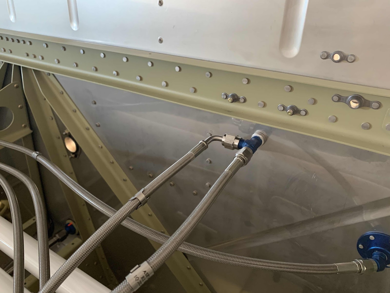
I completed all of the Brake Hose installation in Part 12.....with the exception of the AN826-3D Tee. In the picture below, the blue Tee is final installed with all three connectors. Initially, the Tee was installed into the nipple of the Brake Fluid Reservoir that passes through the Firewall. Then, the two remaining Brake Hoses were installed on the Tee.
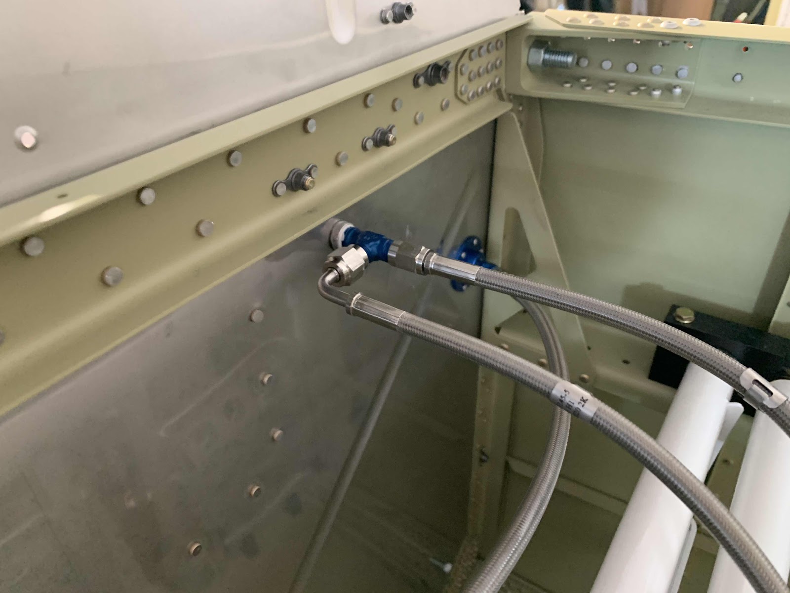
Here is an additional view from the other side. That completes the Brake Hose installation!
These are the CS-00015 Cable Links that originally came from Van’s when I ordered the Fuselage Kit. This is what the Florida air does to metal....pretty quickly. I decided not to try and clean these and just ordered a new part from Van’s. So, the Cable Links in the picture below were put in the scrap pile.

After I got the new part from Van’s, I separated and cleaned them up (shown below). Then, I Akzo primed and top coated them with flat black paint. I will show the completed Links in the next session when I install them in the plane.

The next step was to install the two F-01497A (large) and F-01497B (small) Cable Guides. In the picture below, you can see two angles of the Cable Guides. The large Guides are installed on the aft side with AACQ4-6 rivets and the small ones on the forward side with AACQ4-3 rivets. You can also see how the Rudder Cables route between the two Cable Guides. This view is from the right (copilot) side looking left (pilot) side.....

.....and the left (pilot) side looking right (copilot) side.

I’ll connect the Cable Links during the next session and complete this section.
Install Complete