
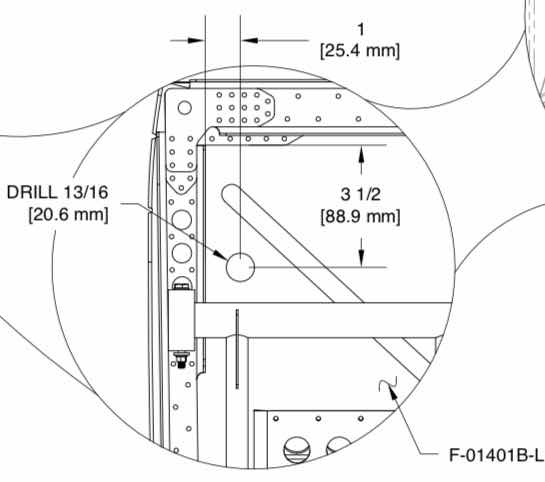
Since I’m building an RV-14 (versus RV-14A), I had to drill two 13/16” holes through the F-01401B-L & -R Firewall Sides. The measurements were taken from the cockpit side off the Firewall as indicated in the plans excerpt below......3.5” down and 1” inboard. The plans instruct you to measure on the aft side of the Firewall and drill from the forward side of the Firewall. So, I figured out where the center was based on the measurements below and used a #40 bit to drill a pilot hole on the aft side. Then, I used my step drill from the forward side to enlarge the hole to 13/16”.
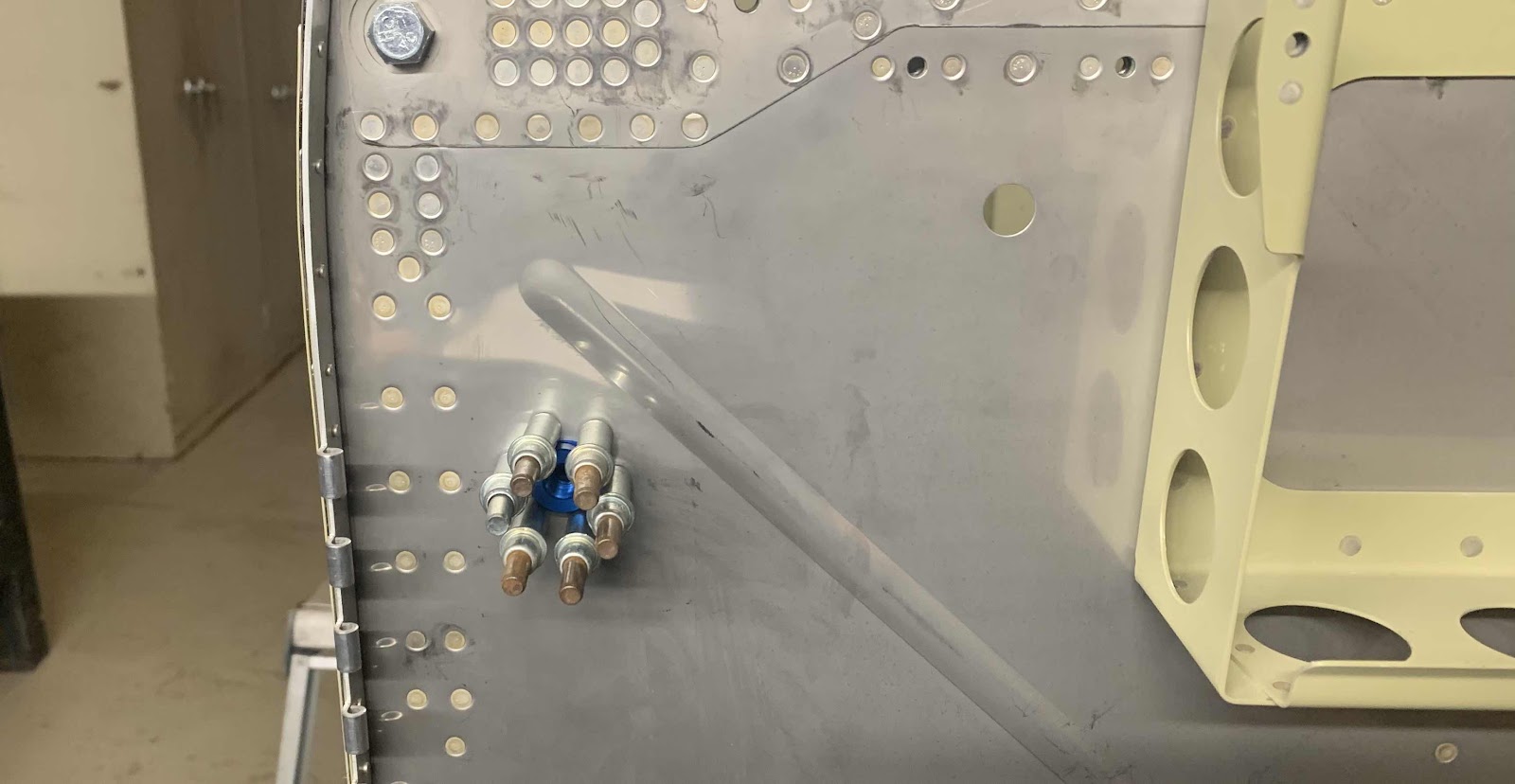
Once the two 13/16” holes were drilled through the Firewall (very nervously might I add), the FLF-00010 Flanged Couplings (blue part in the center of the clecos) were inserted into the holes, centered and the six #40 holes in the Flanges were match-drilled in the Firewall. Below is the forward side of the right Coupling clecoed to the Firewall.....
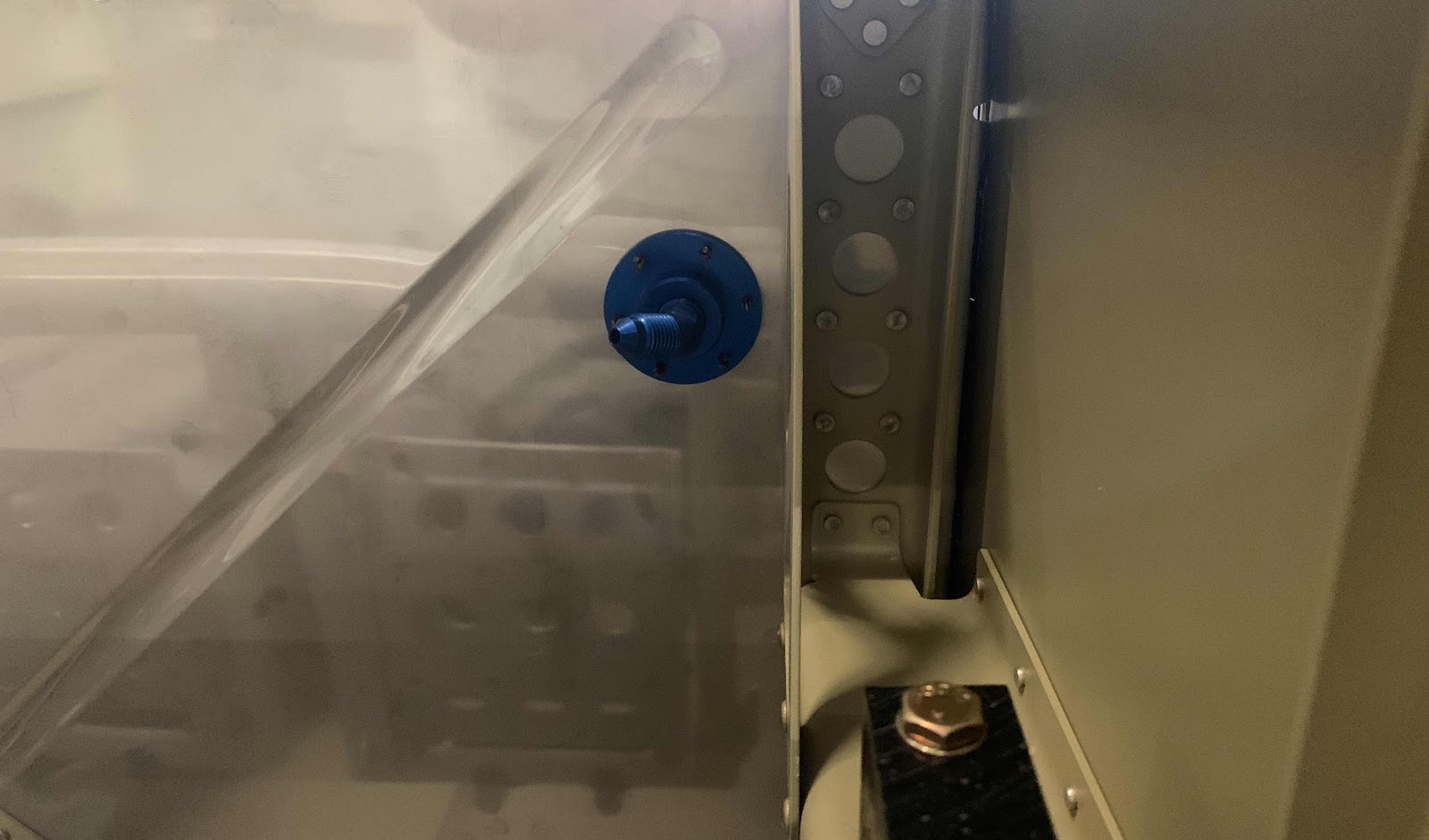
.....and the aft side of the right Coupling.....
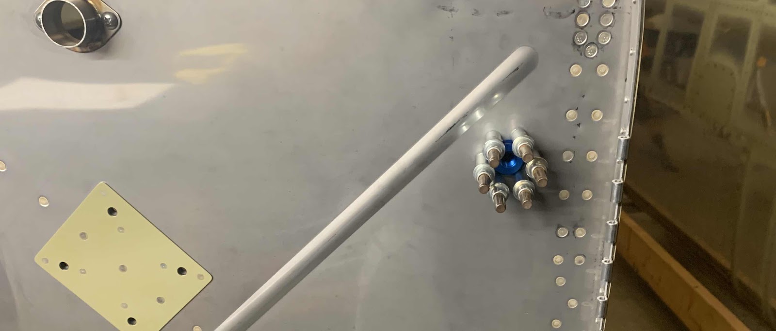
.....forward side of the left Coupling.....
.....aft side of the left Coupling.

I’ll complete the remaining step regarding the Couplings install when I get some proseal.
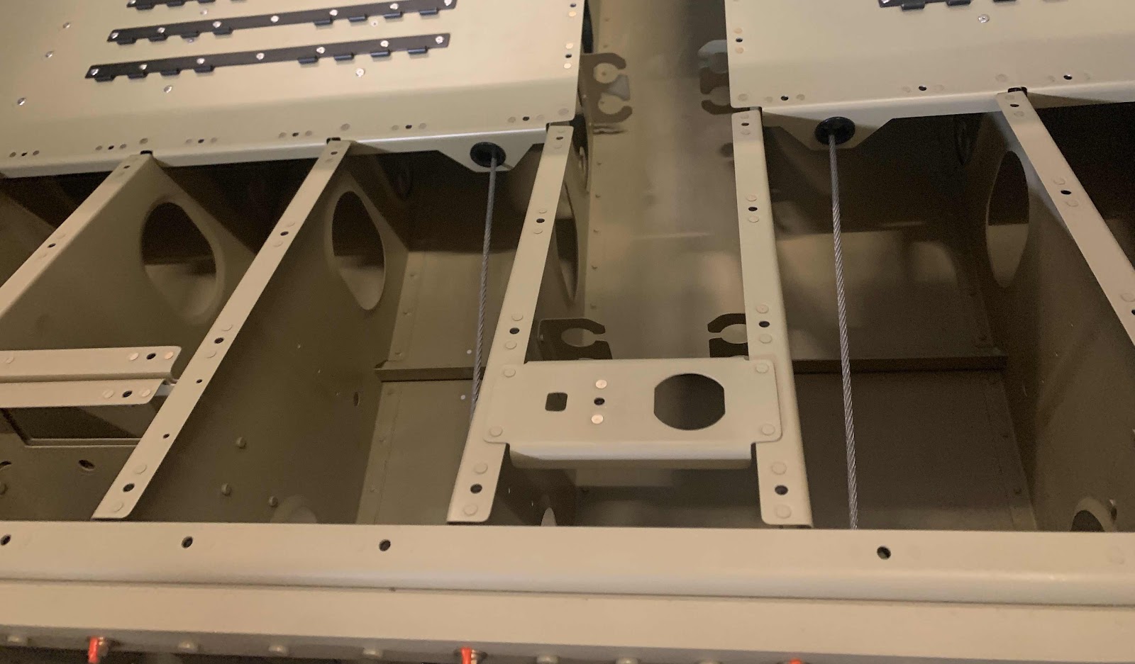
In the meantime, I went on to the routing of the Rudder Cables through the Fuselage as shown below.
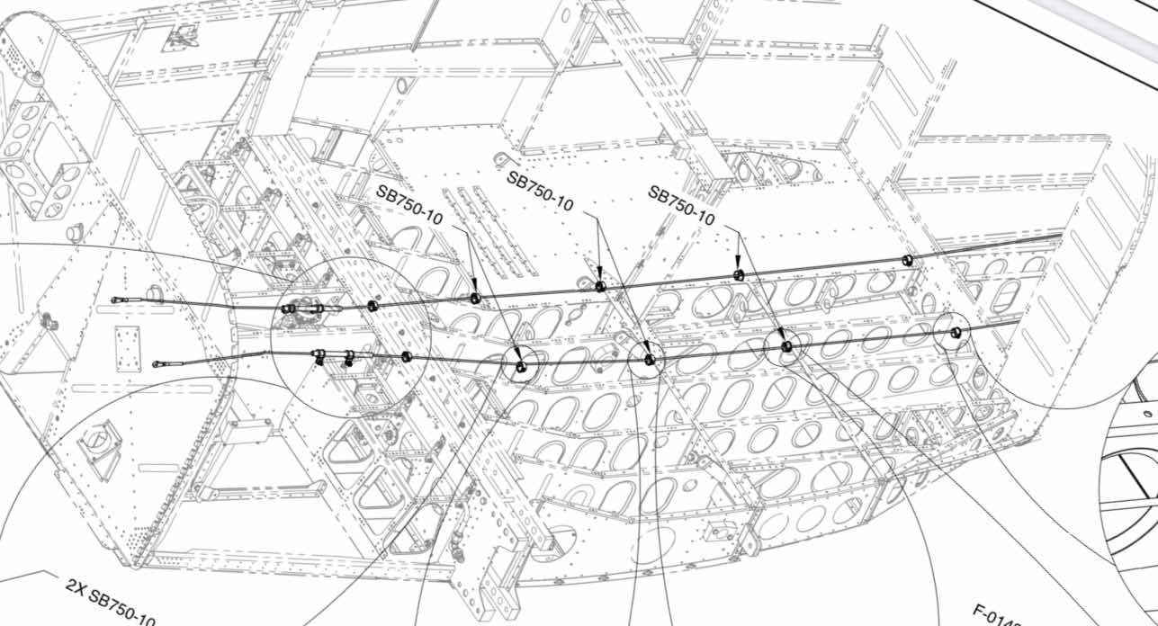
This is looking aft through the rear Fuselage.....

.....through the seating area.....
.....and outward toward the Rudder Pedals (on the left).....

.....and on the right.

This is a close up of the polyethylene sleeve that the Rudder Cable will run through near the Fuel Lines. It will eventually get clamped to the Rib next to it. This is the left side.....

.....and the right side.
