
In this session, we will install the Lens on the wing (again, we are only doing the right Wing for now). To start, we aligned the Lens in the opening using the lines we previous drew on the tape and used the “orange tape handle” to pull it tight against the inside of the Wing. The plans says to use plexiglass drill bits to drill holes in.....wait for it, plexiglass. My A&P buddy (who has been helping and guiding me through out the build) said he recommended using a unibit to drill holes in plexiglass. So, that’s what I did. The first step on my unibit is 1/8”, so very close to a #30. After each hole was match-drilled (very carefully), we inserted a cleco. Here is the four holes on the top.....
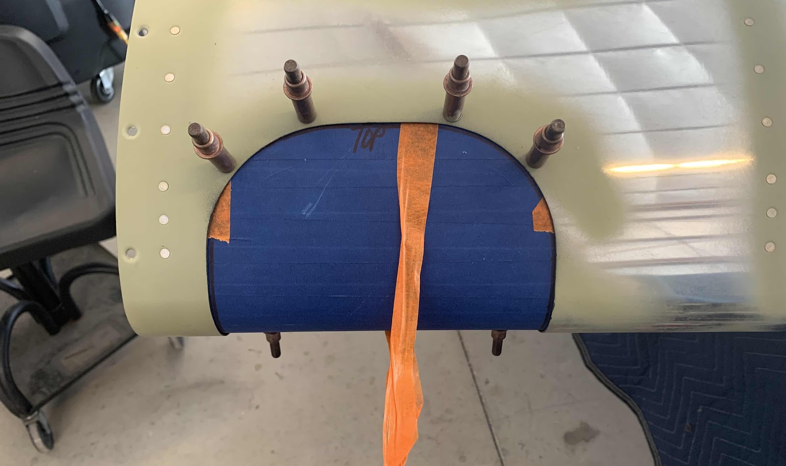
.....and the four holes on the bottom.

Now, for some figuring. The plans say to enlarge the #30 holes (1/8” in my case) we just drilled to #27 and countersink them to accept the dimples for the #6 screws on the Wing Skin. First of all, my unibit doesn’t have a #27 step and I’m scared to countersink the plexiglass. I don’t feel like I can countersink all the holes accurately enough not to introduce cracks (now or later). So, I asked my buddy Jeff. He recommended making the holes large enough to encompass the whole dimple on the Skin. This way, all the holes will be the same, there will be no stress points on the plexiglass created by imperfect countersinks, and the Lens will sit flush on the inside of the Skin all the way around. SOLD!
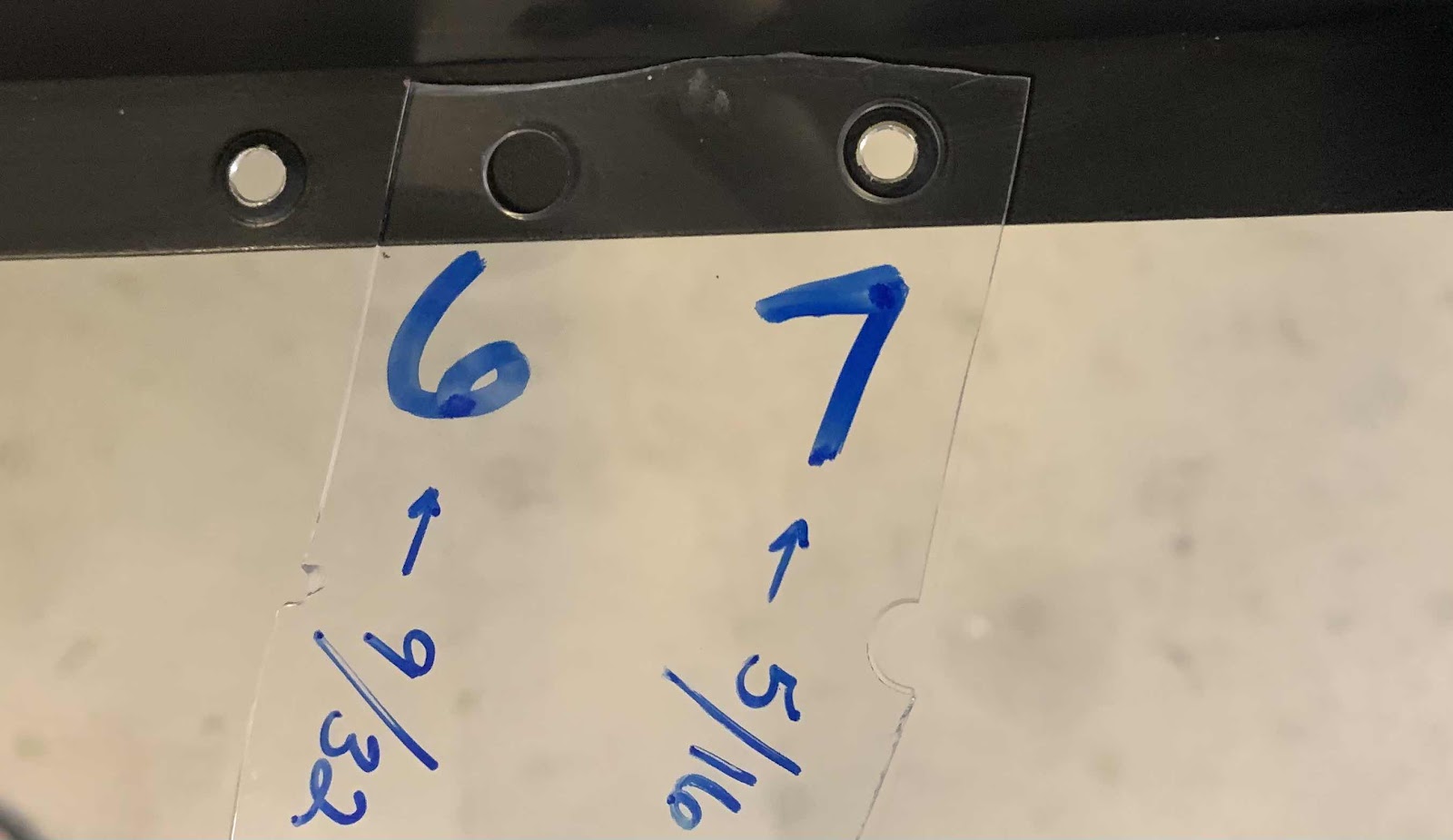
The two holes sizes came down to step #6 (9/32”) and step #7 (5/16”).....this my test piece and jig.

The #6 step was slightly too small and did not completely encompass the dimple or sit flush on the Skin.
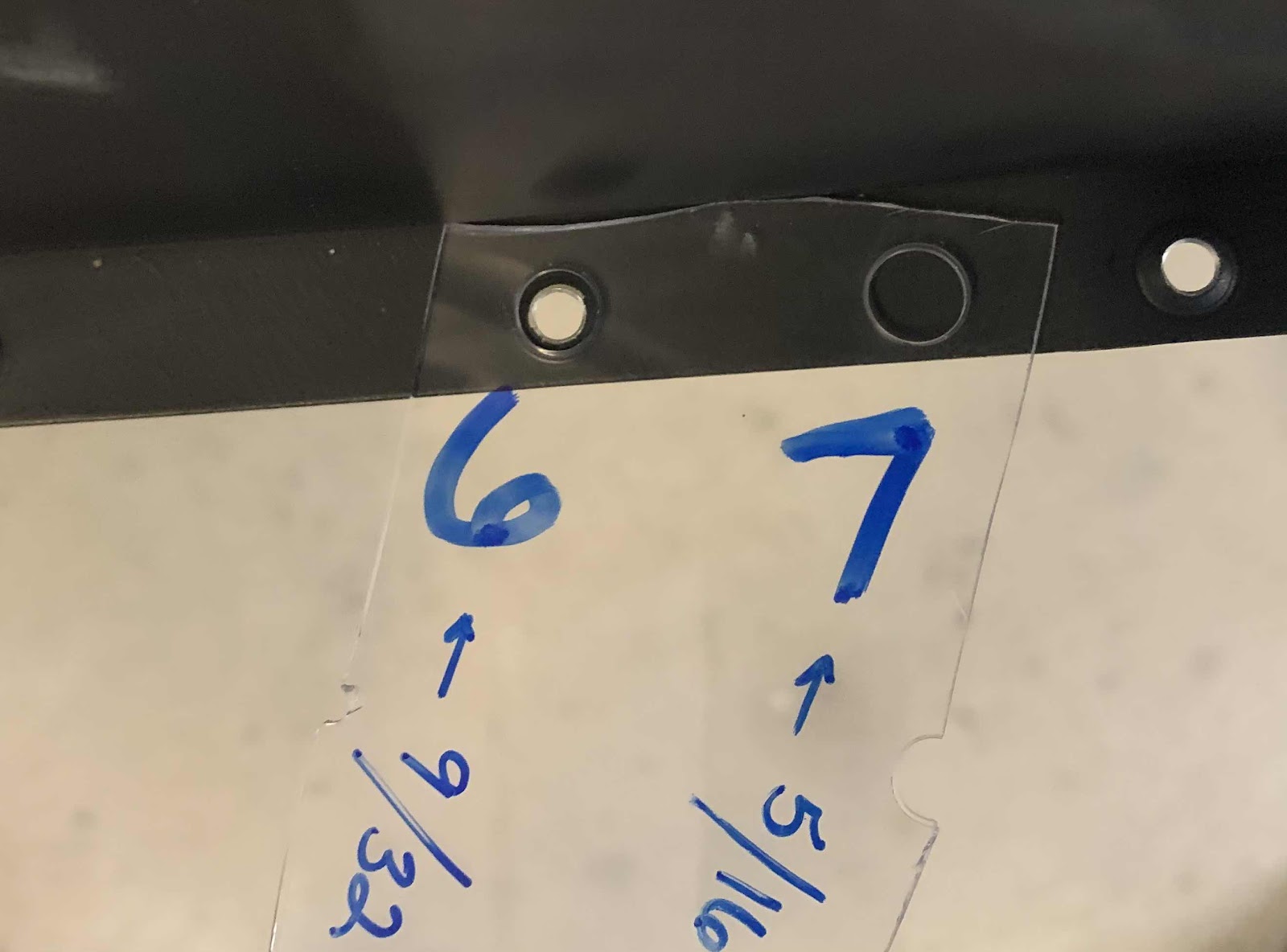
The #7 step fit perfectly around the dimpled hole and sat completely flush on the Wing Skin. So, #7 it is!
After bracing the Lens on the corner of the table, here are the four holes cut to the #7 step on the top.....
After bracing the Lens on the corner of the table, here are the four holes cut to the #7 step on the top.....
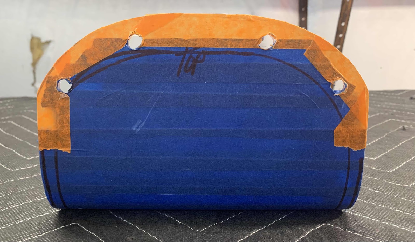
.....and the bottom.

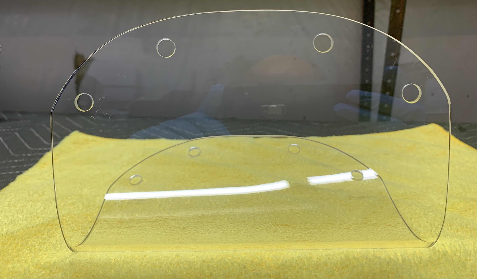
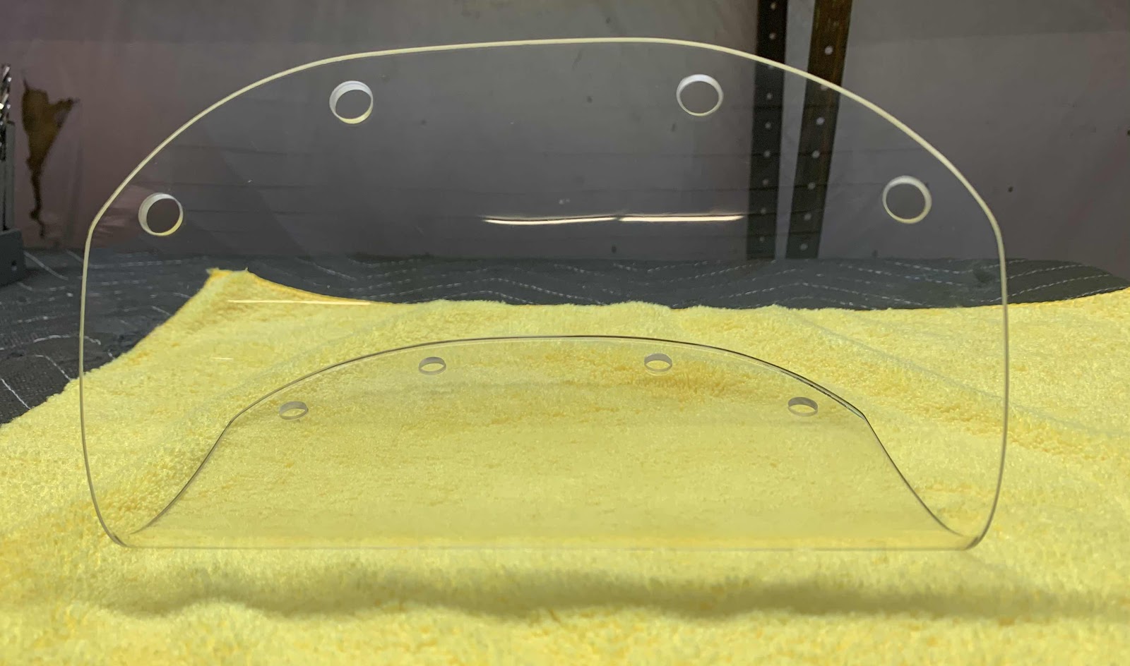
After removing the tape, here is what the holes looked like....all the same sized holes and no cracks.
Lastly, we installed the Lens on the Wing using the two backing plates shown in Part 33. Here’s the completed install showing the top.....

.....and the bottom.

Once completed, we covered the Lens with a microfiber cloth to keep dust and debris off and help prevent scratches. Turned out pretty good I think. We will use the same method to complete the Lens for the left Wing in a later session.
