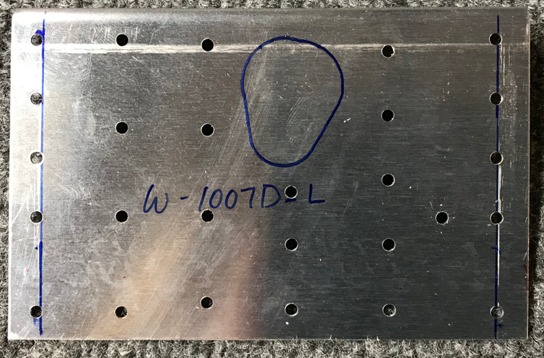
Today’s session started with drawing a parallel line at 5/16” from each edge of the four W-1007D Rear Spar Doublers (two on each Rear Spar) as shown below. I used my square to make the lines on each of the four Doublers and to keep them.....well, square!

The Rear Spar Doublers were aligned on the Rear Spar by nesting the upper flange of the Doubler underneath the upper flange of the Rear Spar and centering the line drawn above with the outboard-most row of attach holes as shown in the plans excerpt below:

The Doubler plate below (right in the excerpt above) was originally attached by aligning the 5/16” line and then clamping the Doubler to the Rear Spar. Once it was clamped in place, all the holes you see in the web were match-drilled (using the holes in the Rear Spar as drill guides) to #30. The holes in the flanges (where the silver cleco’s are installed) were match-drilled to #40. I installed clecos in each of the holes after match-drilling to aid in keeping the Doubler aligned correctly.

The Doubler plate below (left in the excerpt above) was attached using the same method as the first. However, you can see this plate is slightly different and missing several holes in the upper middle portion of the plate.

This is the opposite side of the Doubler shown above. The blue “shape” was drawn by tracing the same shaped pre-punched hole in the Rear Spar. The material inside the blue line will eventually be removed and sanded to exactly match the hole on the Rear Spar. In later steps, this hole will be used to allow the Left Aileron Pushrod to pass through the Rear Spar to Left Aileron.

This is the smaller Doubler plate of the three installed on the Left Rear Spar. This Doubler was aligned by nesting the upper flange of the Doubler underneath the Upper Flange of the Rear Spar and the Doubler with the outer edge of the Rear Spar. The web holes were match-drilled to #30 and the Flange holes were match-drilled to #40.....also, using the Rear Spar as drill guides.

