
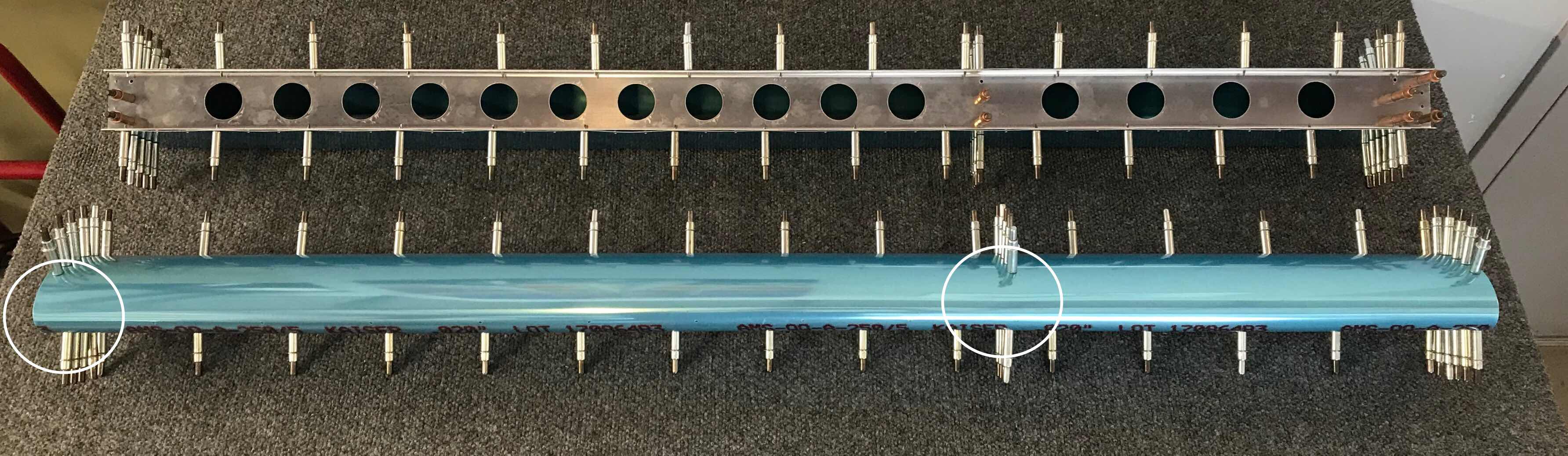
Today’s session was kind of long and I got a lot of work accomplished. To begin, I clecoed the Inboard Nose Rib, Doubler, and two Nose Ribs to the Spar as shown below. (The left Aileron is on the top and the right Aileron is on the bottom). The next step is to cut a length of ST304-065x1.375 Steel Tube to 34.625 inches. These Steel Tubes will serve as the Aileron Counterbalances. I found the the two Steel Tubes supplied by Van’s (also in the picture below) were almost exactly the correct length. Each Tube was about 1/32” short.....which won’t be a problem.

Next, the Nose Skin was clecoed to the lower Spar Flange and the Counterbalance was layed into the Nose Skin so its edge was aligned with the outboard edge of the Nose Skin. The Nose Skin was then clecoed to the upper flange of the Spar and all the Nose Ribs. This essentially “trapped” the Counterbalance between the inside of the Nose Skin and the two Nose Ribs. The picture below shows the Left and Right Ailerons clecoed together as described above. There were two #40 holes that had to be drilled in the locations of the two white circles. The holes were match-drilled from the Nose Skin into the Counterbalance.....using the Nose Skin hole as a drill guide.
Once those two #40 holes were drilled, the Spar was removed exposing the Counterbalance on the inside of the Skin. Here you can see how the Counterbalance was “trapped” as I described above.

The next step seemed difficult at first while reading the plans, but turned out to be rather easy. The two lower holes of the Nose Ribs had to be match-drilled #40 into the Counterbalance and clecoed. I used a 6” #40 drill bit, inserted through one of the Spar attach holes, to reach the lower hole of the Inboard Nose Rib as shown in the first picture below.....and then clecoed in the second. Additionally, I marked the location of the upper Nose Rib hole on the Counterbalance for later drilling.


I followed the same procedure for the Outboard Nose Rib.....6” #40 drill bit through one of the Spar attach holes, then clecoed, then marked the upper hole. I completed this process two times.....once for the Left Aileron and once for the Right Aileron.


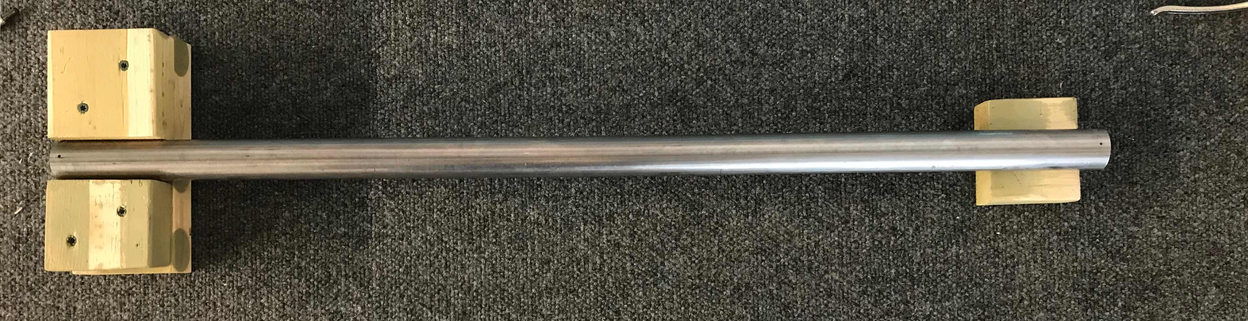
The Counterbalance was then removed from the Nose Skin. The two #40 match-drilled holes in the lower tabs of the Nose Ribs were final-drilled to #27 and the two marked holes in upper tabs were first match-drilled to #40 and then final-drilled to #27. To keep the Counterbalance from rolling while I was drilling the holes, I made this “holder” to keep it still. It worked great. The four tabs in the Nose Ribs were also final-drilled to #27.
Once the four holes were final-drilled to #27, the Counterbalance was attached to the Nose Ribs using AN526C632R8 screws and AN365-632A nuts as shown below. Here is the Inboard Nose Rib.....

.....and the Outboard Nose Rib.

You will definitely need something like these two little guys to get the job done....it’s pretty tight inside the Counterbalance.

Now, everything gets clecoed back together like in the second picture above. There are 10 holes in the leading edge of the Nose Skin that need to be match-drilled into the Counterbalance (the two holes on either end were previously match-drilled). The 10 holes are located in the white box in the picture below. Initially, the holes were match-drilled #40 using the holes in the Nose Skin as a drill guide. Then, the same 10 holes were final-drilled to #30. After each hole was drilled, a cleco was installed to keep the Counterbalance from being pushed away from the Nose Skin while being drilled. Eventually, LP4-3 blind rivets will be installed in these 10 holes.

That’s it for this session.....lots of work accomplished today.