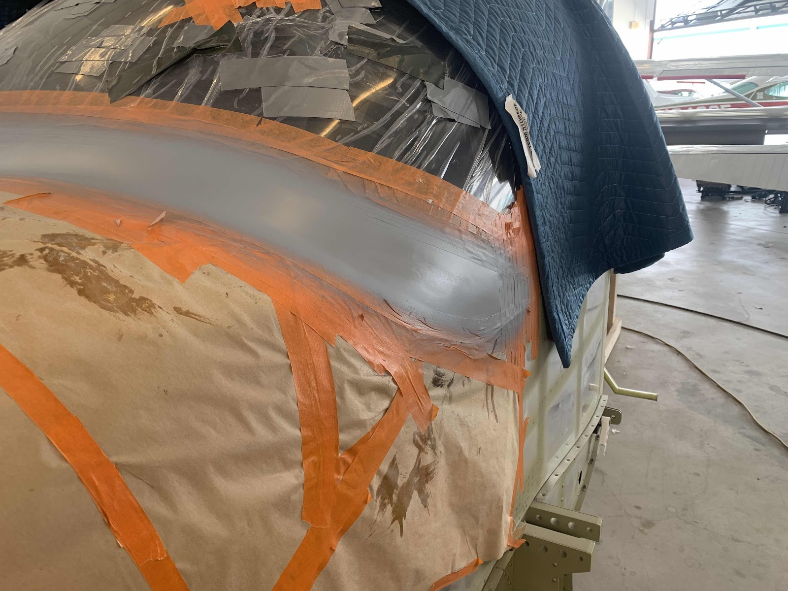
Sunday, June 13, 2021

Service Bulletin 18-09-17

This work session was completed on June 5, 2021

This service bulletin is due to cracking of the F-01478 Aft Fuselage Forward Bottom Skin.  The service bulletin was released after I ordered my kit, so I ordered the appropriate parts to comply with the bulletin.  Here is the LINK to service bulletin on the Van’s website.  My Uncle was in town to help install the Wings, so he also helped me out on completing/complying with the service bulletin.

A total of five individual parts were used and installed as instruction in the bulletin.  Shown below are three of the parts and their final installed location in the airplane:

Part #1:  F-14147-R Stiffener Clip (left circle)
Part #2:  F-14148B Stiffener Doubler (middle circle)
Part #3:  F-14147-L Stiffener Clip (right circle)
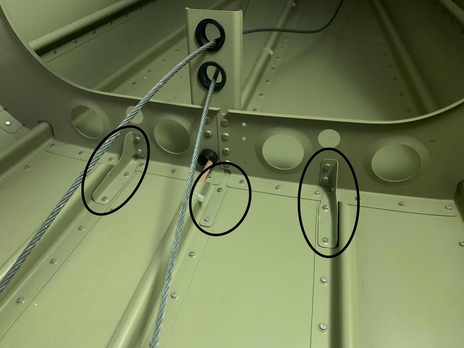
This is aft side of the picture above.  The circles on the left and right are just showing the manufactured side of the AN470 rivets installed on the two Stiffener Clips.

Part #4:  F-14148C (center circle)

Part #5:  F-14148A Skin Doubler

The round end of the Skin Doubler is oriented forward and the blunt end is oriented aft.
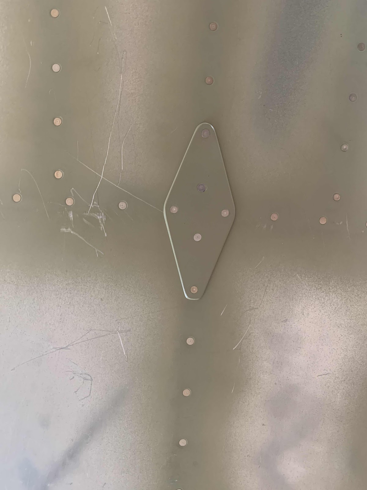
Service Bulletin Complete
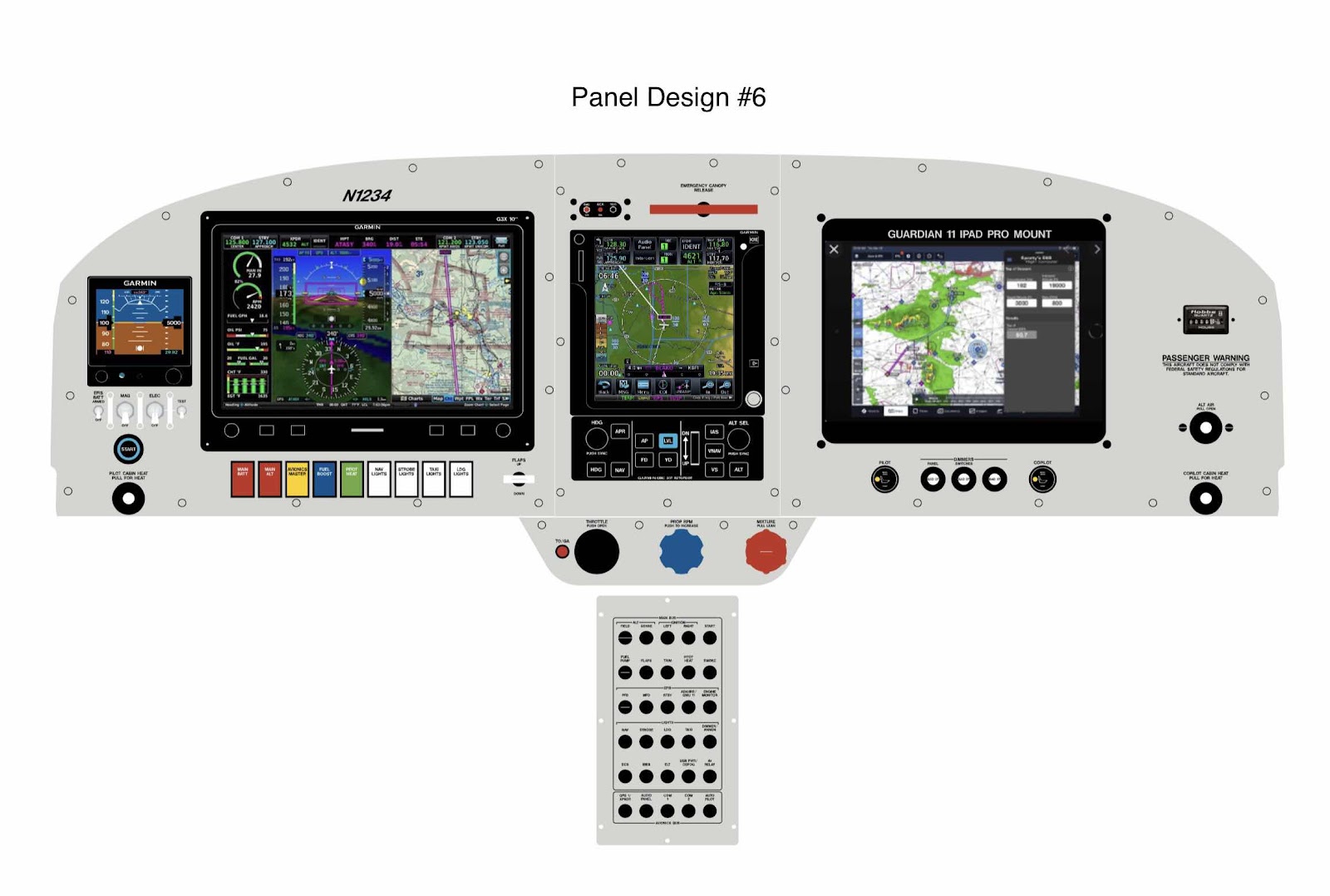
Panel Design (Part 6)

Below is Panel Design #6 from Aerotronics (sent to us on June 7, 2021) with the following changes:

1.  All of the spaces were removed between the row of switches under the G3X
2.  Those switches were then centered between the left edge of the G3X and Flap switch

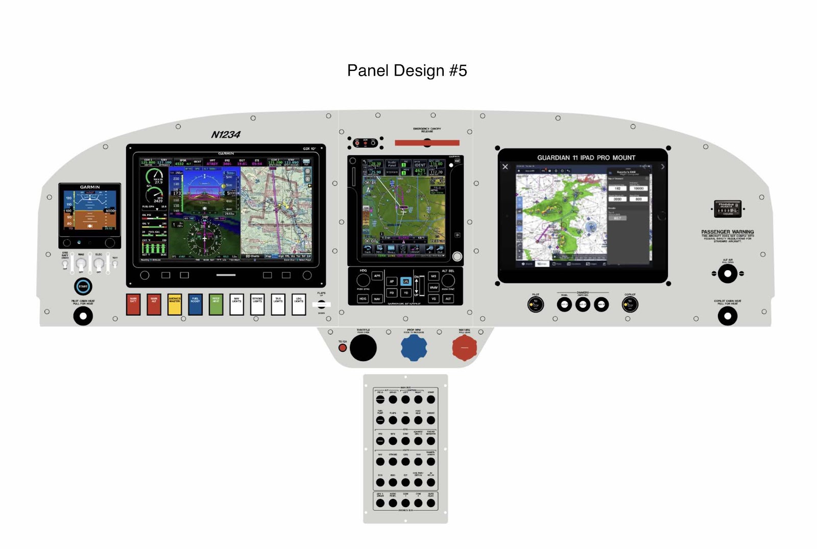
Panel Design (Part 5)

Below is Panel Design #5 from Aerotronics (sent to us on June 7, 2021) with the following changes:

1.  An “EFIS STANDBY BATTERY” switch was added to the left side of the panel with the “Mag” switches
2.  The yellow “EFIS BATT MASTER” switch was removed from the row of switches under the G3X
3.  All of the switches were equally spaced out under the G3X
4.  The “BATTERY MASTER” switch was renamed “MAIN BATT”
5.  The “ALT FIELD” switch was renamed “MAIN ALT”

Finishing, Tail Dragger Landing Gear and Engine Mount (Part 3)

This work session was completed on April 30, 2021

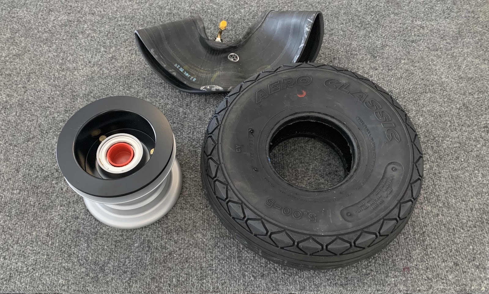
The next step in the process is the assemble the wheels and tires.  The three “pieces” for each Wheel Assembly came from Van’s in the Finishing Kit as shown below.  This was my first time doing this, so Jeff (my A&P buddy) showed me how to go it correctly.  The plans also provide VERY good instruction on how to do it also.

1.  U 55-204 Wheels from Groove Aircraft Landing Gear Systems Inc (x2)
2.  U 5.00x5-6 Aero Classic Tires (x2)
3.  U 5.00x5-6IT Inner Tubes (x2)


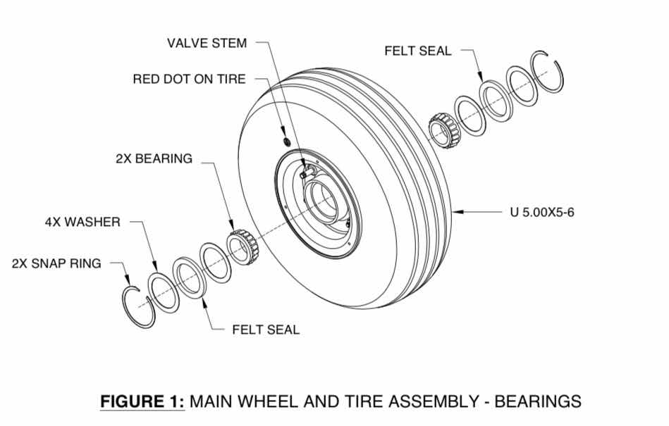
To begin, the bearings were removed from the Main Wheel Assembly as illustrated below (excerpt from the Van’s plans).  Once separated, I greased the bearings and re-installed them by reversing the step below.
(Excerpt from the Van’s RV-14 Builder Plans)

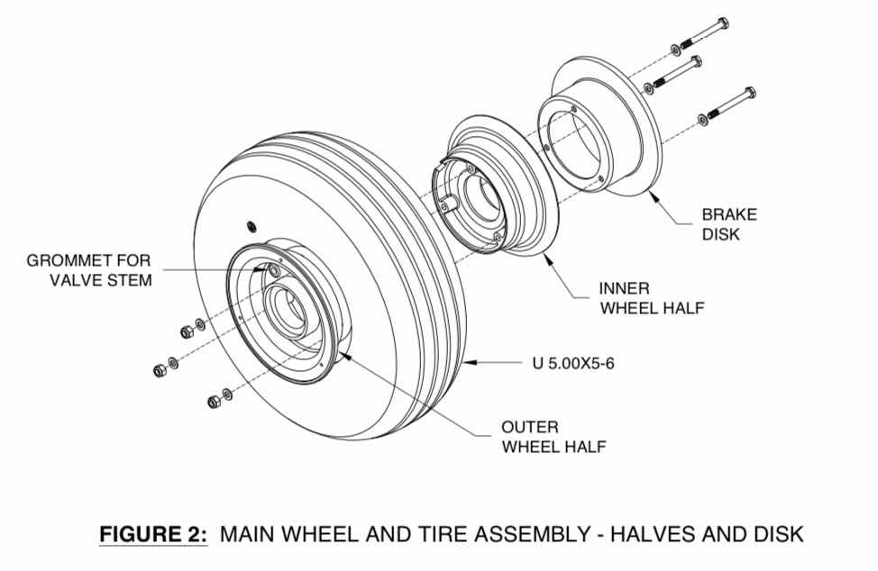
Next, the the Main Wheel Assembly was split in half by removing the three bolts holding them together as illustrated below (excerpt from the Van’s plans).
(Excerpt from the Van’s RV-14 Builder Plans)

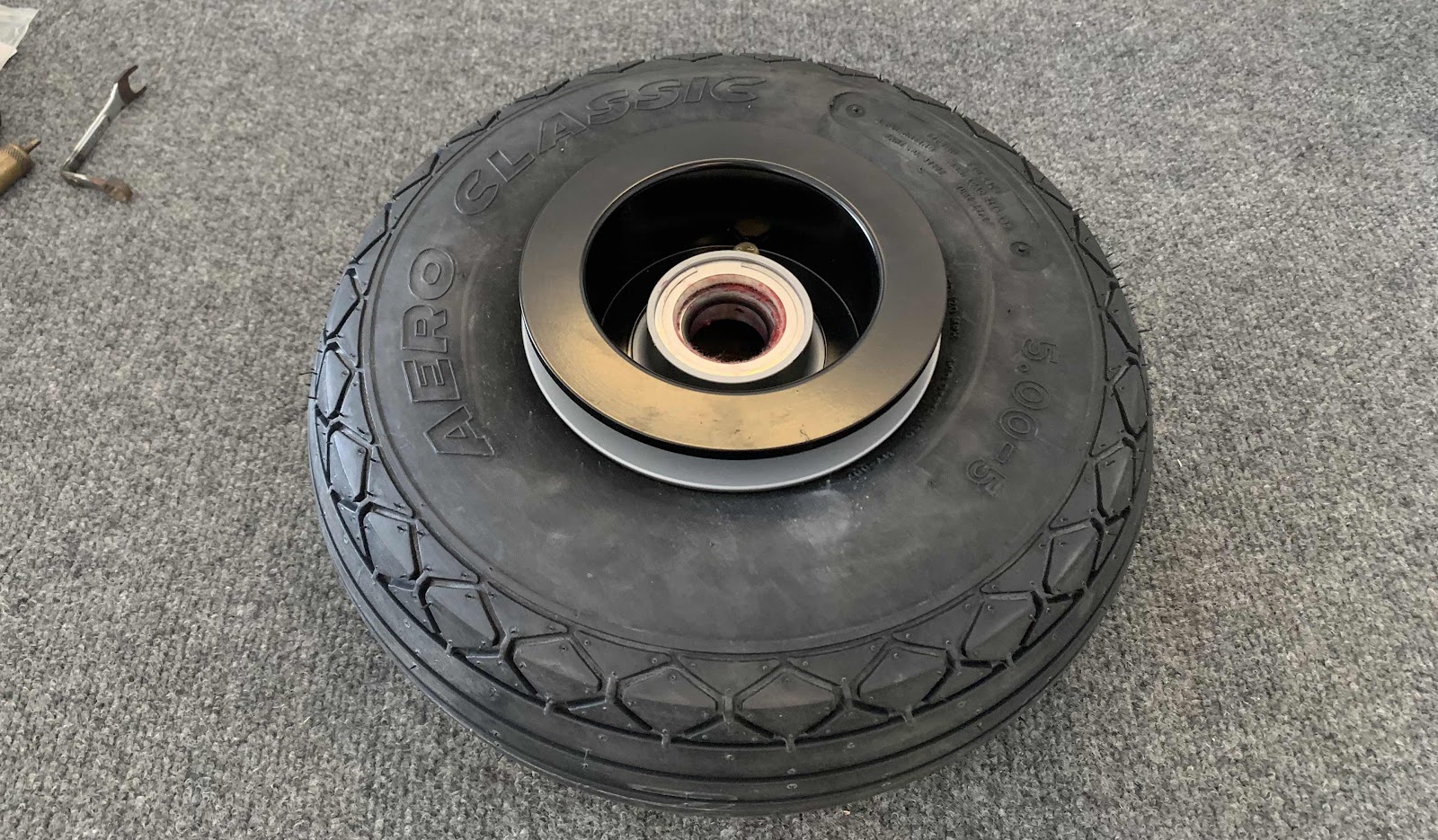
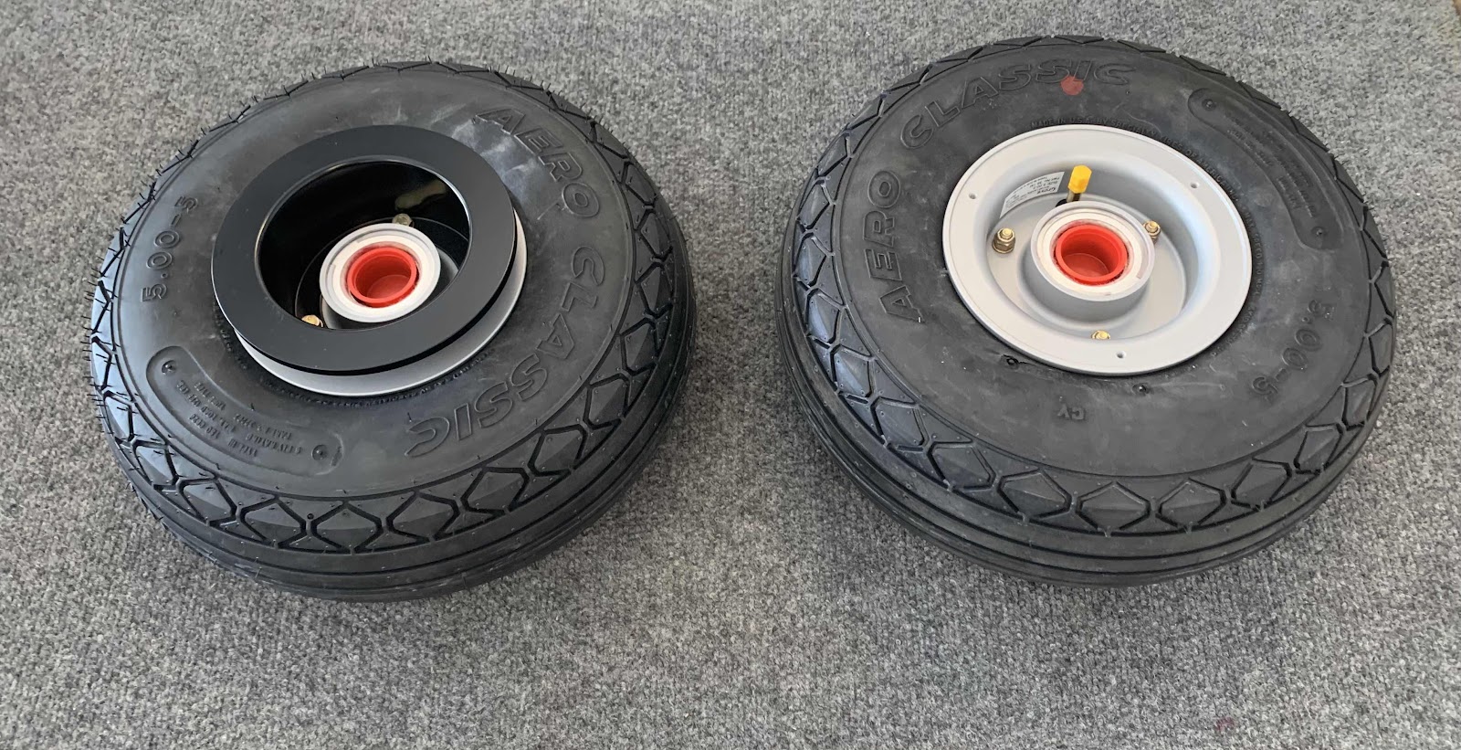
The Main Wheel Assembly was put back together with the tire and tube in place and torque to 90 in lbs (as indicated on the inside of one of the wheel halves).  The tire was inflated to 25 psi (and deflated) to make sure the tube wasn’t getting pinched and inflated to it’s final pressure of 40 psi.  Here is the “outside” of the completed Main Wheel Assembly.....

.....the “inside” of the Main Wheel Assembly.....

.....and both together.

Session Total:  1.5 / Tail Dragger Landing Gear & Engine Mount Total:  3.6

Saturday, June 12, 2021

Panel Design (Part 4)

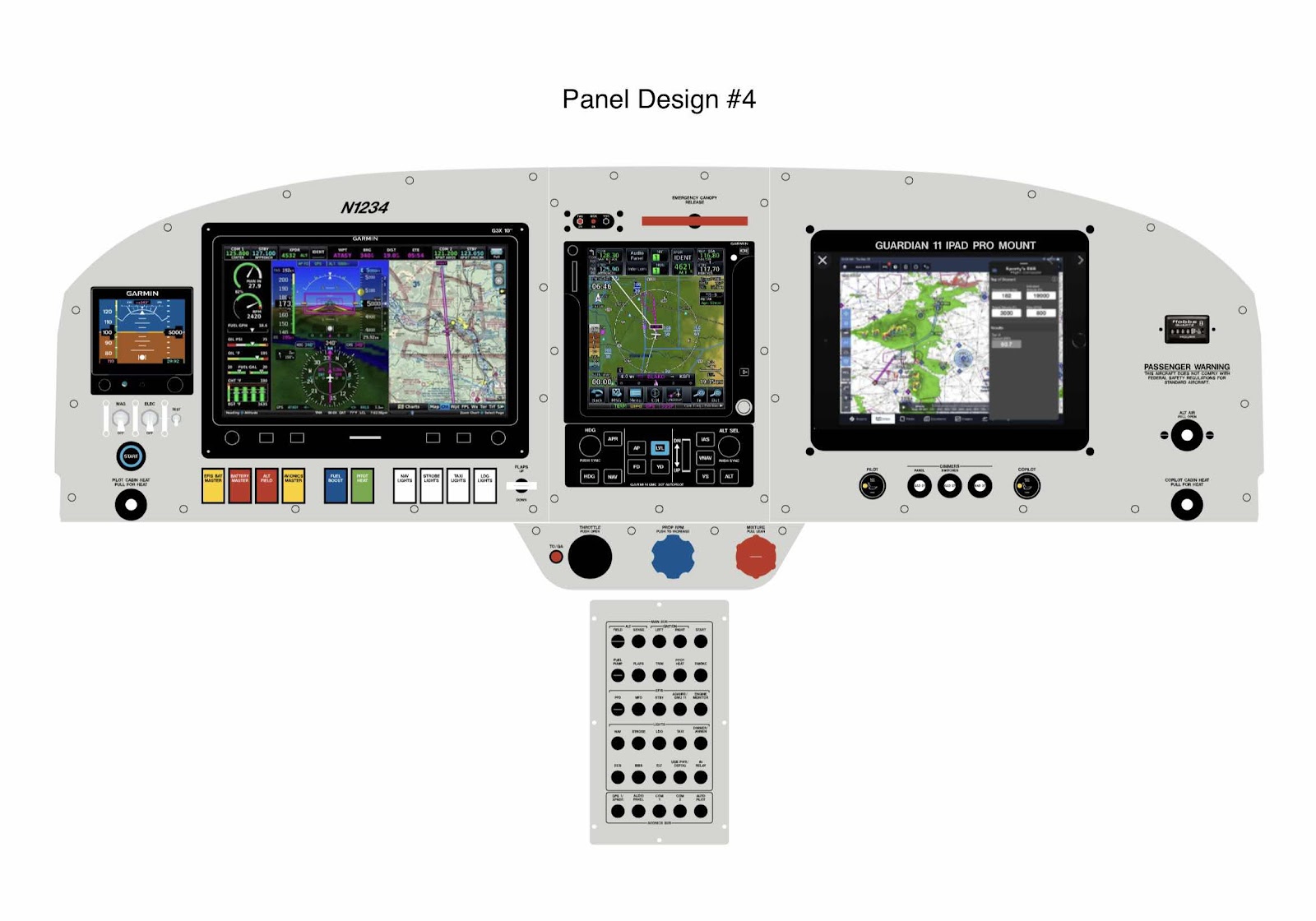
Below is Panel Design #4 from Aerotronics (sent to us on June 2, 2021) with the following changes:

1.  An analog HOBBS meter was added to the right side of the panel
2.  The Seat Heater switches were moved to either side of the dimmer switches under the iPad mount
3.  Three guards were added to the Mag switches on the left side of the panel 

Finishing, Seatback (Part 1)


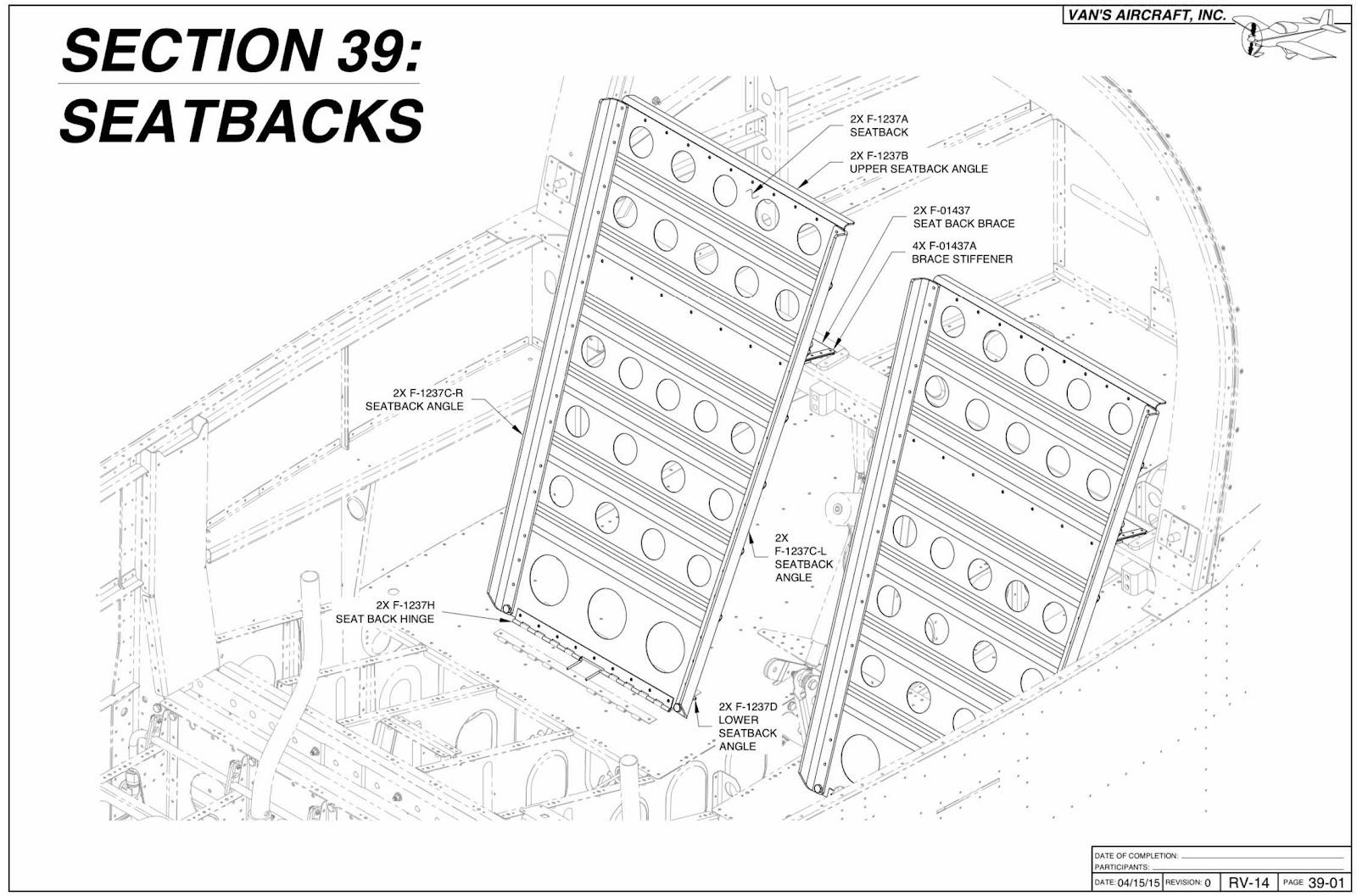
We won’t be completing this section.  We ordered a complete interior from Classic Aero Designs including seats, side panels, carpet and stick boots.  We are expecting delivery of our interior in October.  When the interior arrives, I will post it’s installation in the “Interior” section on the right.

Finishing, Tail Dragger Landing Gear and Engine Mount (Part 2)

This work session was completed on April 27, 2021.

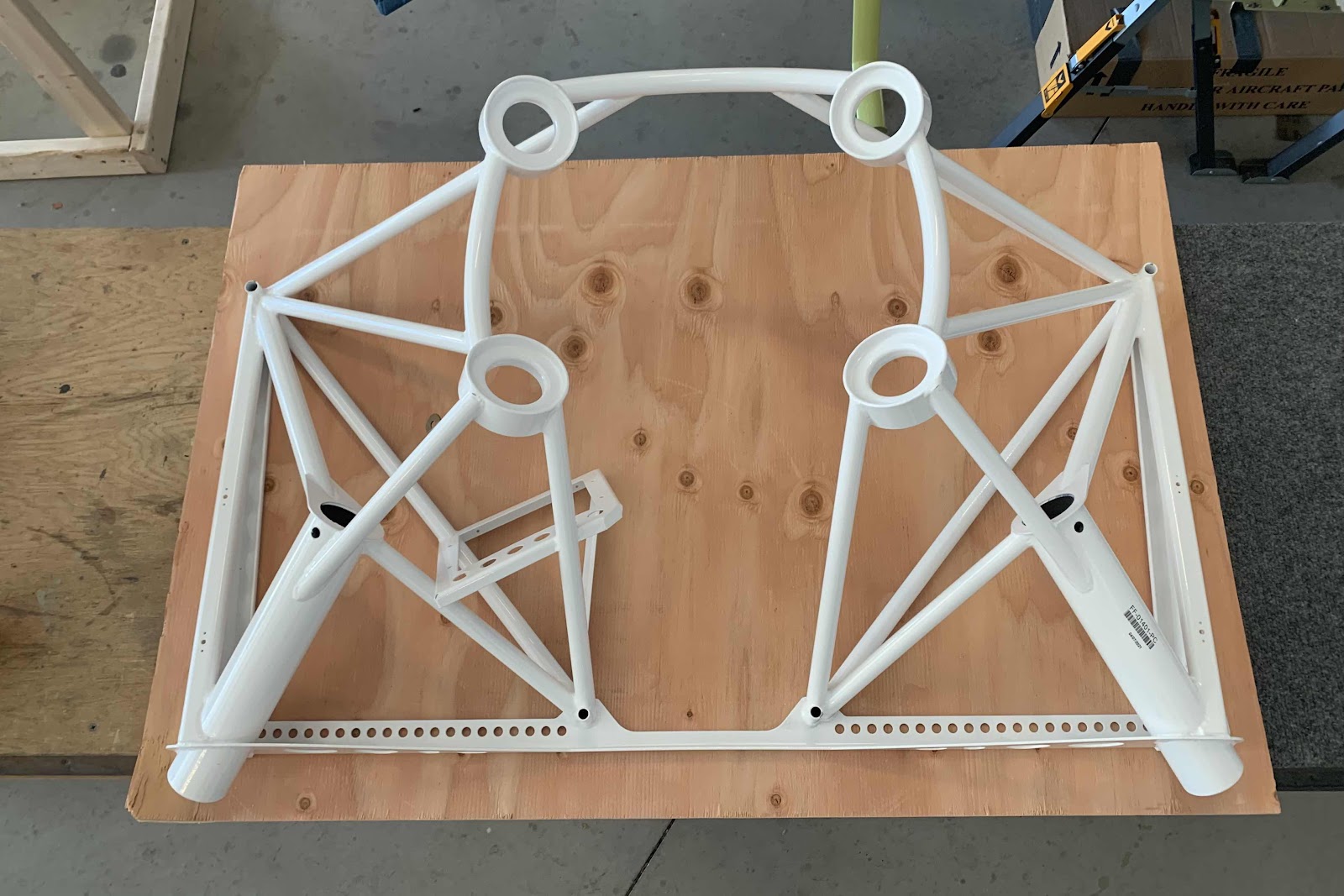
The Finishing Kit arrived on October 26, 2020; however, the engine mount was unfortunately on backorder.  On April 26, 2021, the engine mount FINALLY arrived.....ironically, it was exactly 6 months!  The engine mount arrived screwed to this sheet of plywood in a big cardboard box.

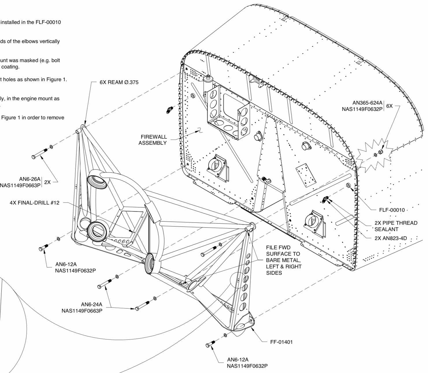
The first step was to install the two FLF-00010 Flanged Couplings on the Firewall.  These Couplings will be used for the hydraulics lines down to the wheel brakes.  After that, six AN6 bolts of various lengths will be used to attach the engine mount to the Firewall has described below.

(Excerpt from the Van’s RV-14 Builder Plans)

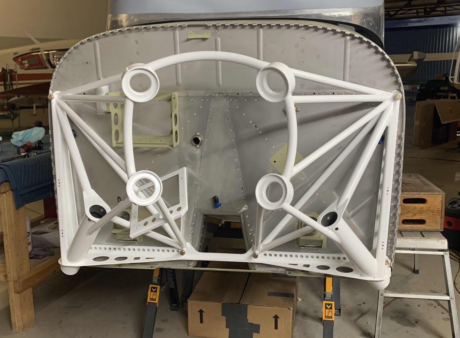
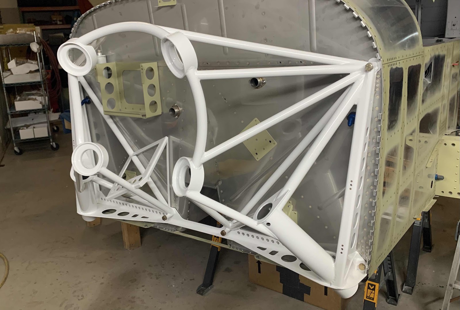
Here is the engine mount final installed to the Firewall.  This view if from the right side.....

.....straight on.....

.....and the left side.  The gear can now be installed during the next session.

Finishing, Wing Attachment (Part 2)

This work session was completed on November 25, 2020.

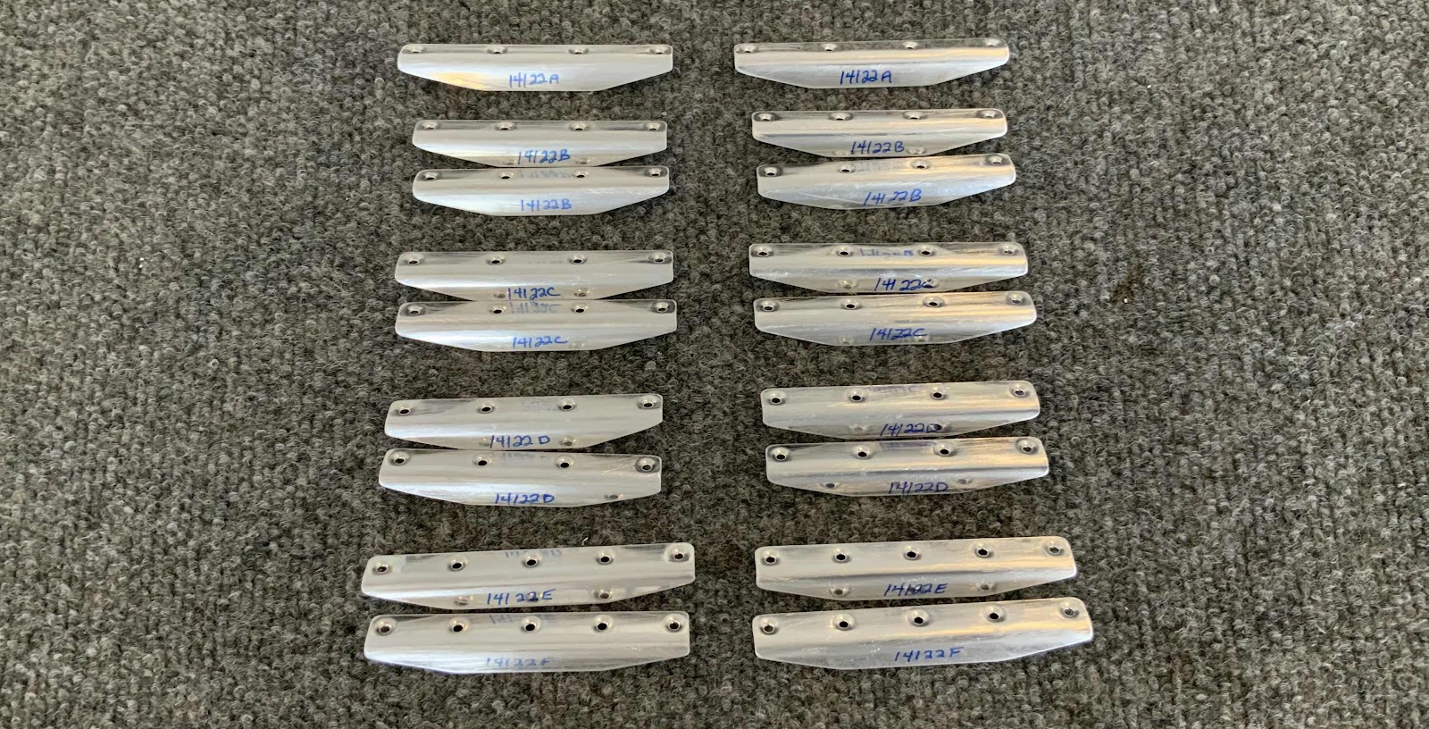
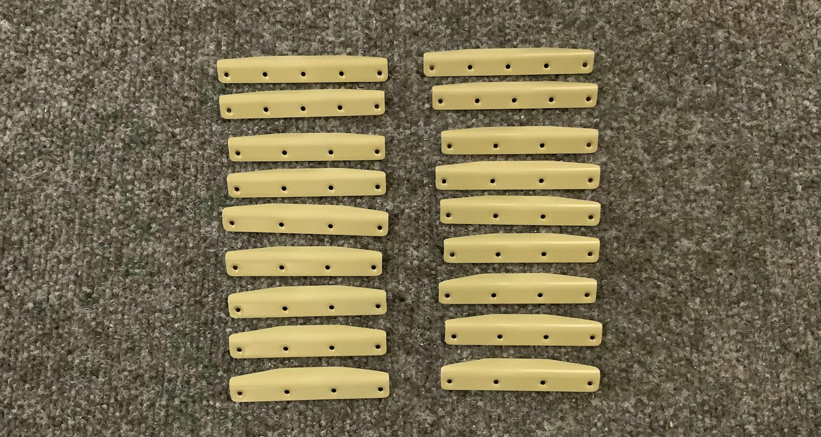
These are the F-14122A Root Fairing Stiffeners (left column for the left side and right column for the right side).  They came from Van’s in two long strip and each Stiffener had to be separated and “shaped”.  These are the completed Stiffeners after being separated, “shaped” and dimpled.....

.....and after being treated with Alumiprep, Alodine and Akzo Primer.  They are now ready for installation.

Finishing, Taildragger Gear Leg and Wheel Fairing (Part 1)


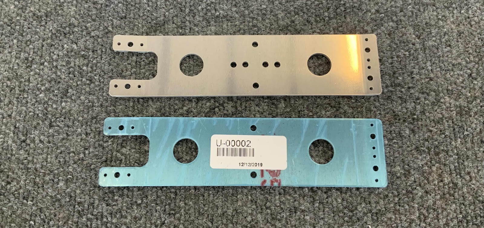
While I was at it, I decided to prepare the U-00002 Wheel Fairing Brackets.  All the holes were deburred, edges cleaned and nutplate attach holes were countersunk.

This pictures shows the four completed Brackets.  Following their preparation above, the two Brackets on the left were treated with Alumiprep and Alodine, sprayed with Akzo Primer, appropriate nutplates installed and sprayed with a flat black top coat of paint.  The two Brackets on the right are steel, so they were not treated with Alumiprep and Alodine.  However, they did get sprayed with Akzo Primer, appropriate nutplates installed and sprayed with a flat black top coat of paint.  They are now competed and waiting to be installed at some point in the future.

Finishing, Tail Dragger Landing Gear and Engine Mount (Part 1)


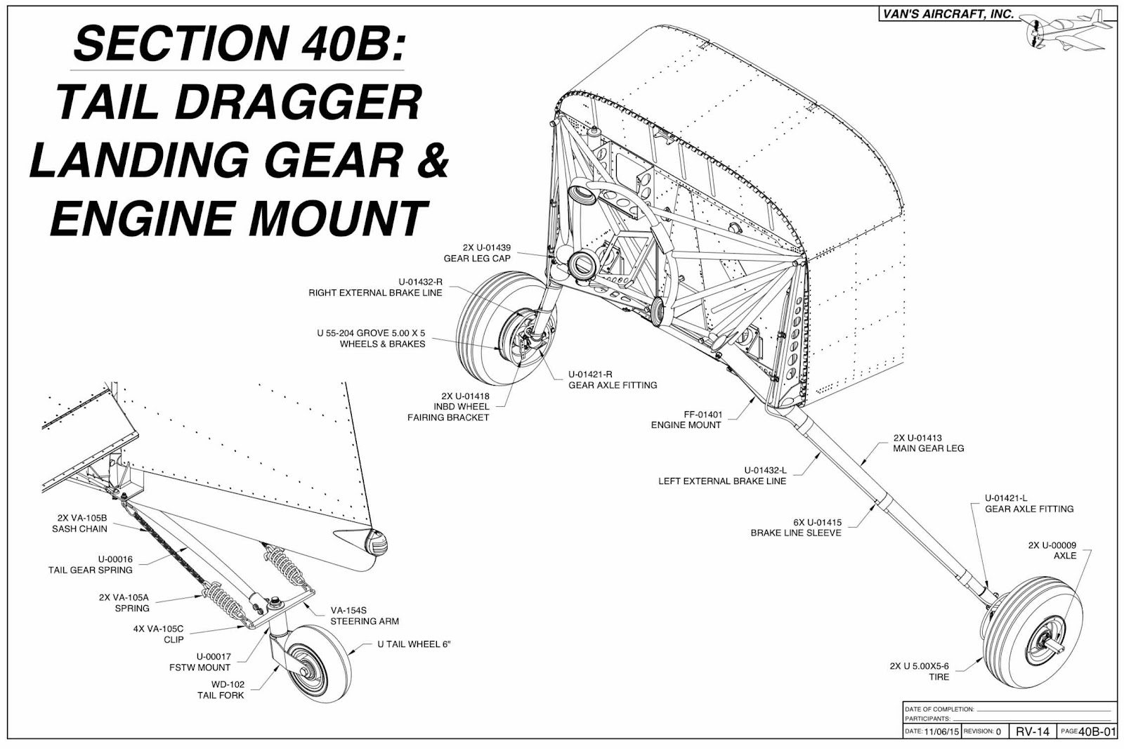
Section 40A, Tricycle Landing Gear and Engine Mount obviously covers the installation of the Landing Gear and Engine Mount on the tricycle RV-14A.  So, we will not be using this section for our tail dragger version RV-14.

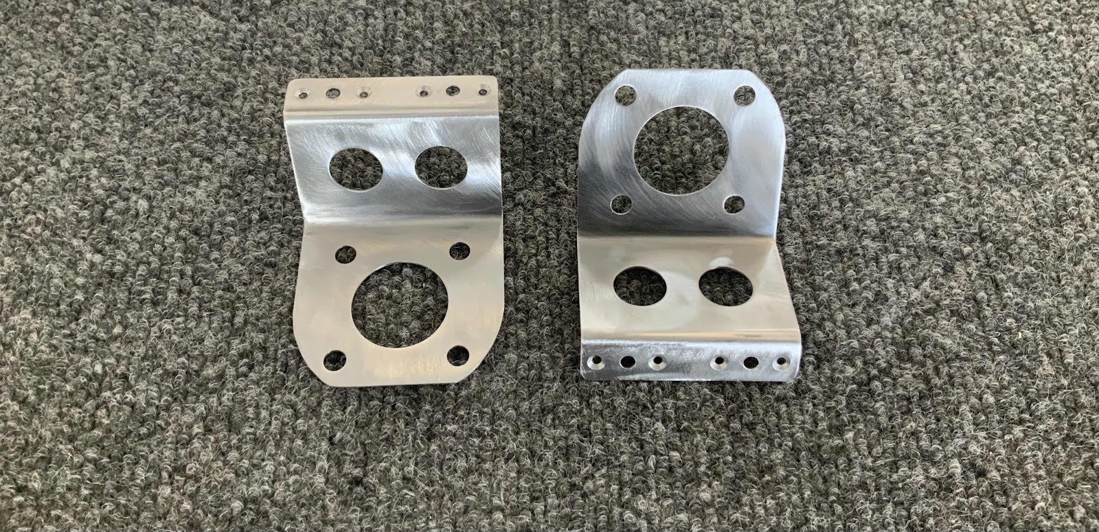
The two pictures below are the U-01418 INDB Wheel Fairing Brackets.  I had these parts for about three weeks before they started showing signs of corrosion.  So, I needed to remedy that problem.  The Bracket on the left shows the beginning of the corrosion I found and the Bracket(s) and the one on the right shows it after I cleaned it up.  I used my Angle Grinder and 2” Fiber Discs to remove the corrosion.

Here are both Brackets after being cleaned of all corrosion.  I also countersunk the four nutplate attach holes on each Bracket.  You can see the eight holes below on the Bracket flanges.

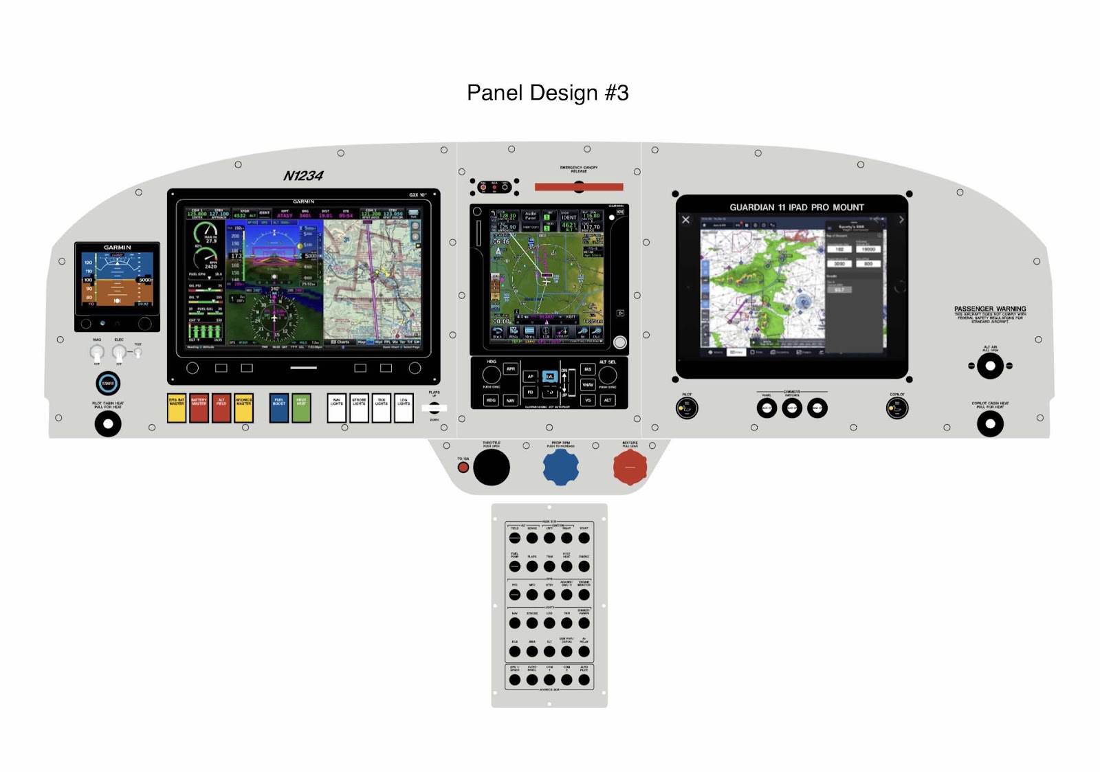
Panel Design (Part 3)

Below is Panel Design #3 from Aerotronics (sent to us on May 27, 2021) with the following changes:

1.  The USB was removed from the panel.  (We will have a USB between the seats from the stock version from Van’s)
2.  “Oil Cooler” knob was removed from the panel
3.  “Alternate Air” knob was put where the previous USB port was located 
4.  The “Passenger Warning” was moved to the right side of the panel
5.  The TO/Go Around button was moved next to the throttle on the bottom bracket

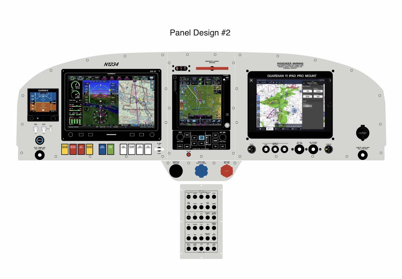
Panel Design (Part 2)

Here is Panel Design #2 Aerotronics sent to us on May 26, 2021.  The changes included:

1.  Moved the “ALT AIR” and “OIL  COOLER” knobs from the under panel bracket to the panel
2.  Added the “Seat Heater” switches to the panel
3.  Removed the “Standy EFIS Battery” switch and added a yellow rocker switch for this battery
4.  Moved the ELT status light from the right side of the panel to next to the Canopy Jettison Handle

We will study this updated panel and see what changes we would like to make.  More to follow.....

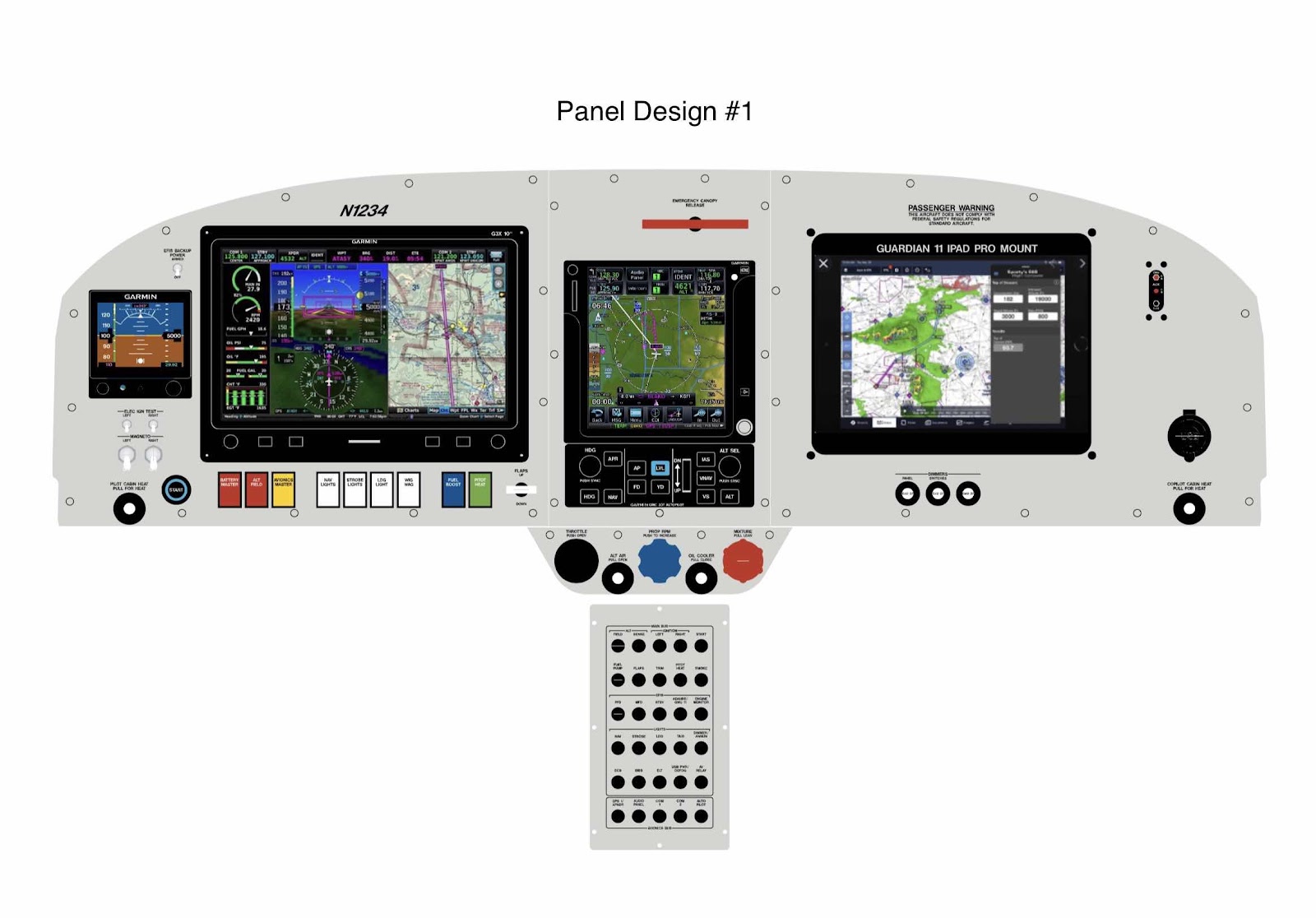
Panel Design (Part 1)

After researching avionics companies, reading reviews in the VAF Forums and talking face-to-face with several companies at Sun-N-Fun, we have decided to use Aerotronics to design, make and build our panel.  We spoke with Andre at Sun-N-Fun this year and started the process.

Initially, he emailed us a rather lengthy questionnaire to fill out regarding some of our needs/wants/must haves, etc.  From the information we provided, he came up with an initial quote (will most likely change a few times before the panel is complete) for the panel and started the design process for our panel.

This was the initial panel design they sent us on May 25, 2021.  The main parts of the panel will include:

10” Garmin G3X Touch (GDU 460)
Garmin G5 Backup EFIS
GSU 25 ADAHRS
GMC 507 Autopilot Controller 
Garmin GTN750xi
GTX 45 Remote Transponder (ADSB In & Out)
GTR20 Remote Comm
Guardian Avionics iPad Mount
GEA 24 EIS
ACK 406 ELT
.....and all the supporting equipment, switches, wiring, etc

From here, Andre says we can make as many changes to the panel design as we need to until we are satisfied.  They will likely start building our panel around October for a Decemeber-ish delivery.  So, we still have several months to finalize the design.  I will post more updates as me make updates with Aerotronics.

Finishing, Wing Attachment (Part 1)


This work session was completed June 2, 2021.

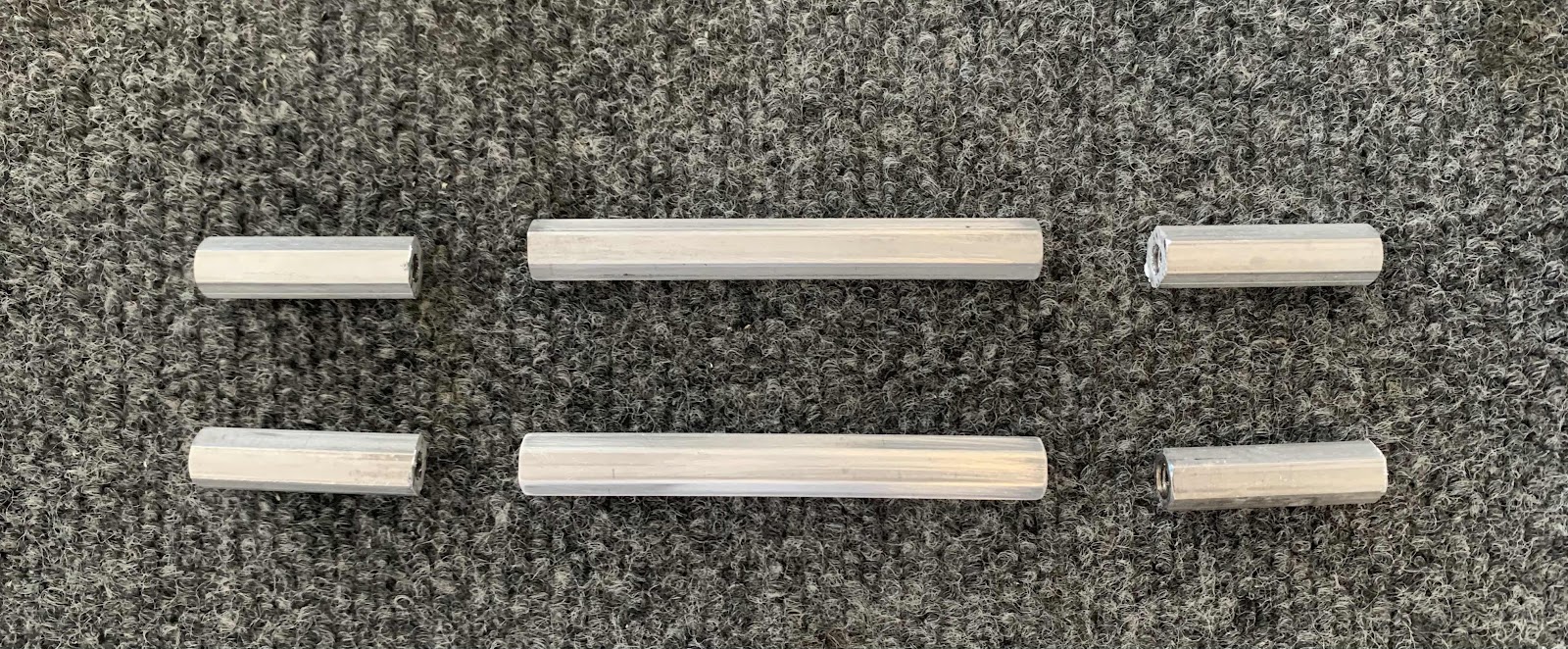
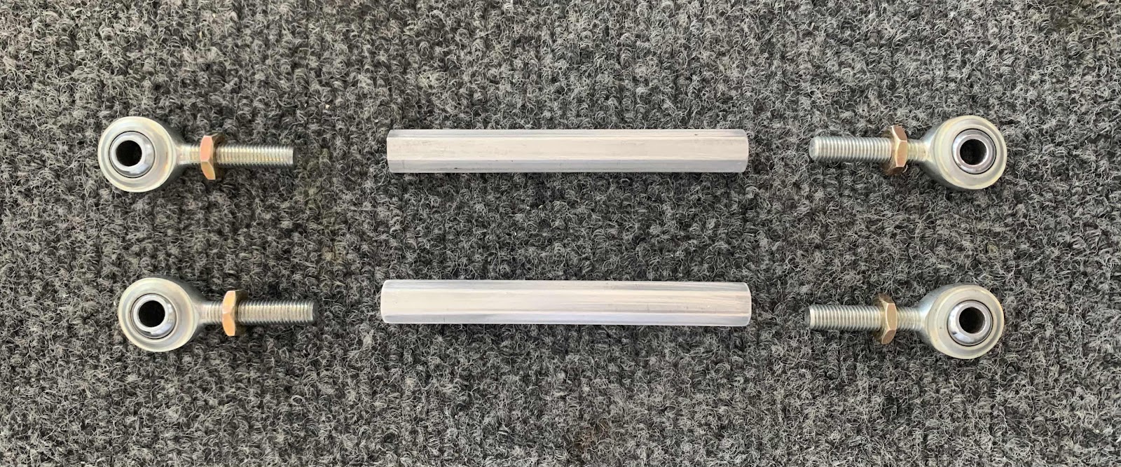
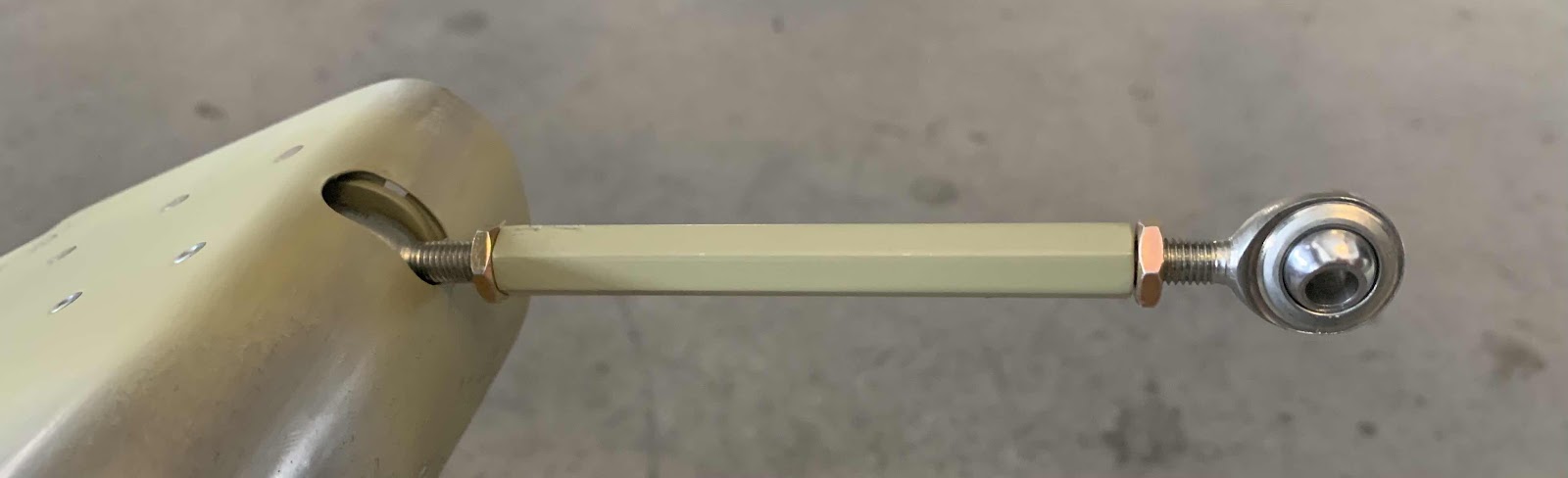
The first step in this section is to fabricate some two Flap Pushrods Assemblies.  To start, the VA-256 Flap Pushrod had to be trimmed to 3 1/2” (88.9 mm).  The center section below is the part that will be used for the actual Pushrod.

These are the parts that’s will make up the assembly:  
VA-256 Flap Pushrod (x2)
CM-4M Rod End Bearings (x2)
AN316-4R Jam Nuts (x4)

The Pushrods were then treated with Alumiprep, Alodine, sprayed with Akzo primer, assembled and installed on/in the Flaps.  Here is the final product:


Lycoming YIO-390-A3B6 Engine Delivered

Our Engine was delivered today (June 6th actually)!!!!!  So, exciting!!!!!

FedEx Freight delivered our engine to the hangar today with this gigantic truck.  Funny thing......our engine was the ONLY thing in the trailer!

As the previous engine post stated when we placed the order, we decided on the “standard or regular” IO-390.  According to Lycoming, they call this engine a YIO-390-EXP60 and this is how it was shipped from Lycoming.  When it was ordered, I requested it be packed with preservative oil because I wasn’t sure exactly when the engine would be installed......better safe than sorry was my approach here. 


As it turns out, Van’s says the Firewall Forward Kit has a lead time of approximately 2-3 months, so good call on the engine preservation.  However, the exhaust system is projected to take 6 MONTHS!  I will definitely have to look into other exhaust systems.....Vetterman, Power Flow, etc.

Anyway, we will start the install when the Firewall Forward Kit arrives.  

The work sessions/posts regarding the installation of the engine will be covered in Section 43, Engine Installation.

Friday, June 11, 2021

Wings, Outboard Leading Edge (Part 35)

In Part 34, the right Lens was installed in the “pre-punched” landing light opening in the right Wing.  During this work session, I installed the Lens in the same opening on the left Wing.  I used the same method as discussed in Part 34.....and here is the result.  After completing all the required trimming of the Lens, these are the attach holes stepped to 5/16” with a step bit.  As in Part 34, I made the holes this large to completely surround (but not touch) the dimpled holes in the wing skin in an attempt to help prevent the Lens from cracking.


The holes in the Wing Skin were dimpled to accept the AN507C632R6 attach screws and the Lens was installed in the Wing.

Here are a couple pictures of the upper and lower W-00018 Backing Plates.  This is the lower plate.....

.....and the upper plate.

Section Complete
Sunday, May 30, 2021

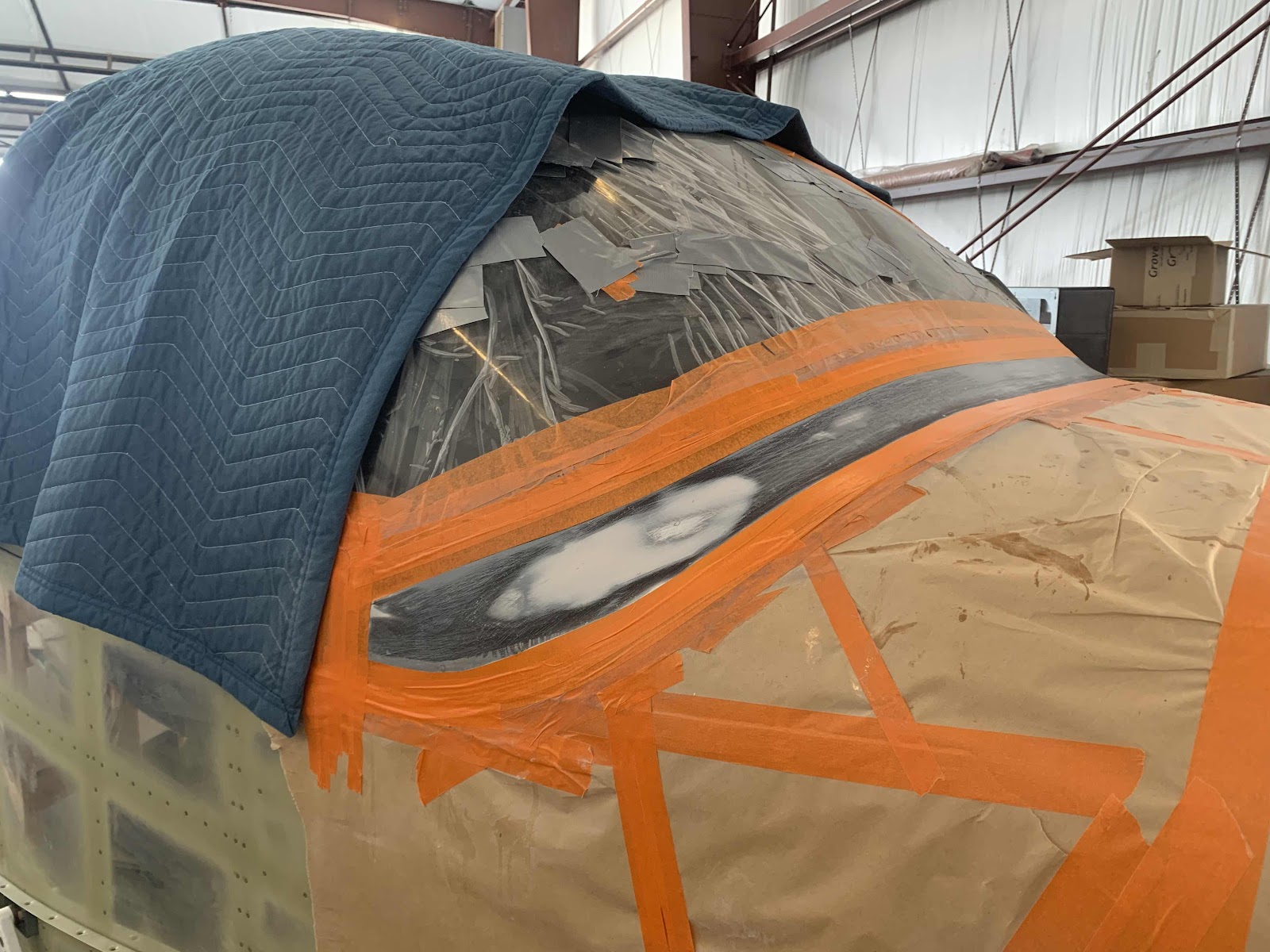
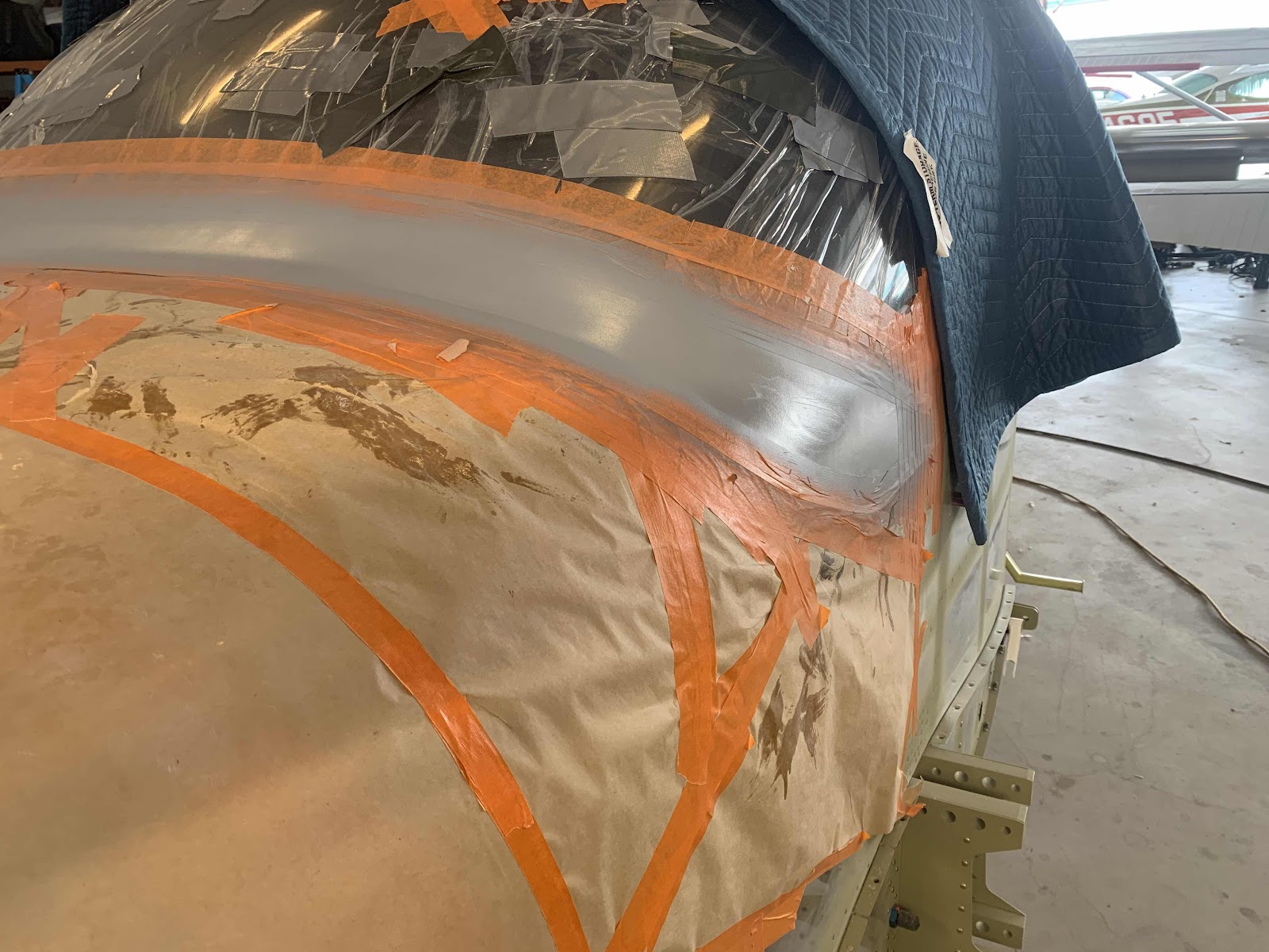
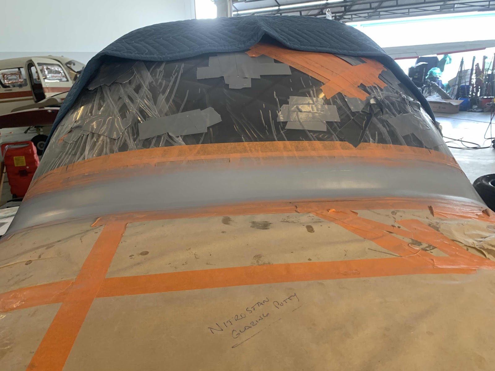
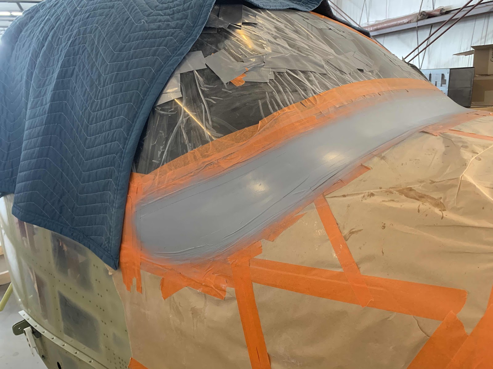
Finishing, Canopy and Window (Part 35, 36, 37)

The work covered in this entry was conducted was completed over the course of three work session between April 6 - 9, 2021