
The work and pictures in the post are from August 30, 2023.
Now, with the two “remote comm mounting plates” riveted to the angles, I can install the transponder tray (and transponder) to the angles. Here are a couple pictures showing the final install. In the first picture, you can see what is the top left side of the bracket. It shows the transponder tray attached to the aluminum angles with the two screws and nuts, the transponder slide in and locked into the tray and the two mounting holes on the remote comm mounting plate for the comm radio.
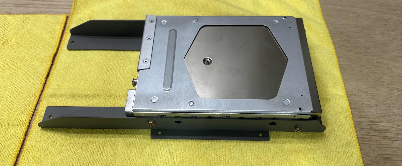
This is the top right side of the bracket showing the same things.

Looking down from the top, you can see the shop heads of all of those 18 rivets, the four mounting holes on the two remote comm mounting plates and the four mounting holes for the glove box flange and firewall angle.

Here is another angle.

The comm radio is on the bottom of the bracket (just like it will be mounted in the plane). I used four screws and nuts to complete the install. This is the left side of bracket/assembly…..

……and this is the right side. I’ll try to show it in the next post, but the pre-installed brackets on the comm radio are not flat and provide some “lift” to the radio. This “lift” provides enough gap between the radio and the shop heads from the rivets I installed on the remote comm radio mounting plates. During the fitting process, I actually had to squeeze a few of the outboard rivets a little more than normal to ensure they cleared the top of the radio and didn’t rub each other.

Finally, this bottom up angle shows the comm radio fully installed on the remote comm mounting plates. If need be, there are two more locations I could add screws to on the remote comm mounting plates.

In the next post, we will mount the bracket/assembly in the plane.