
Tonight’s session started with temporarily installing the left Aileron on the left Wing using AN3 bolts. This is necessary to ensue you have the proper clearance between the Aileron and the Wing Tip. This picture shows the Aileron attached to the Outboard Hinge Bracket.....
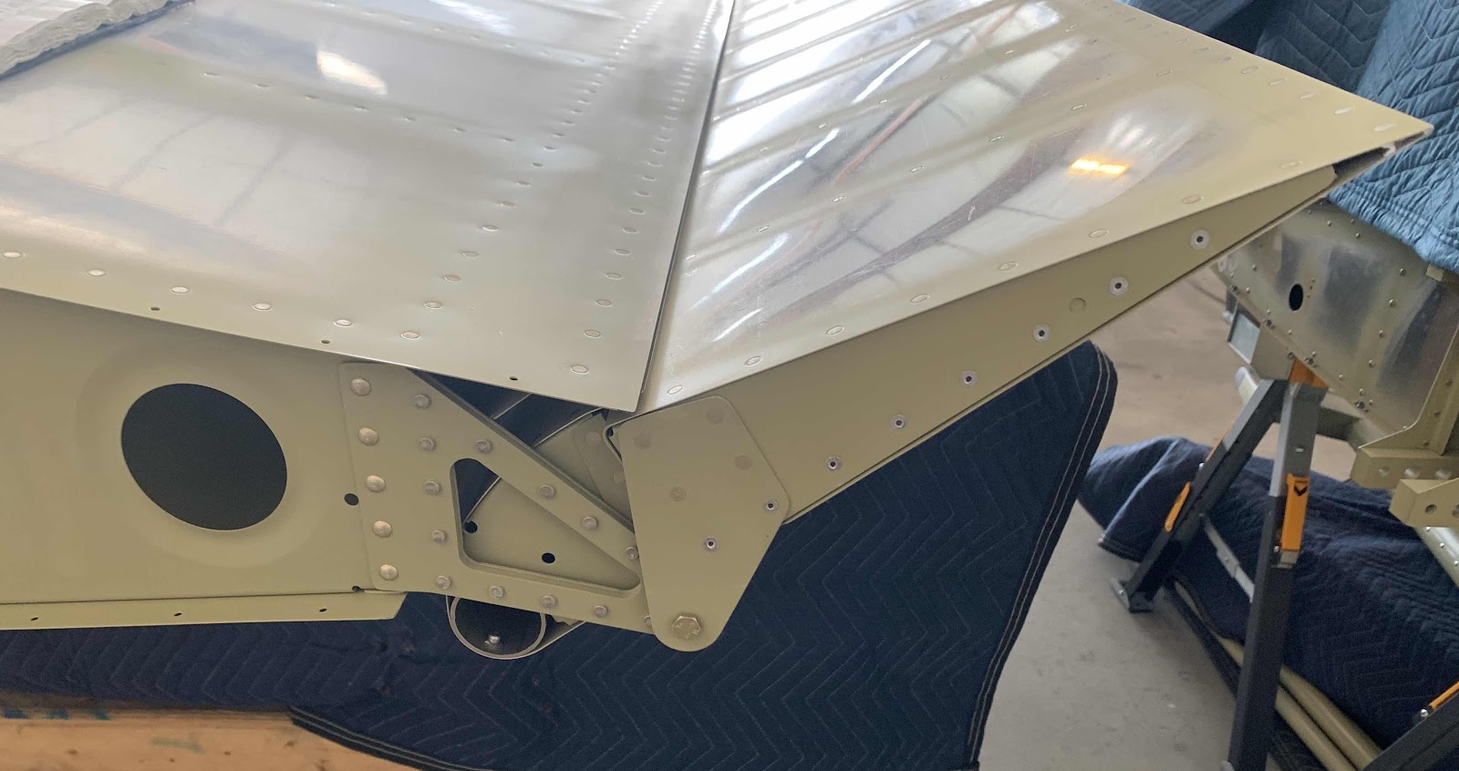
.....and the Inbound Hinge Bracket.

One area the plans are specific about are:
“Verify the gap spacing between the forward edge of the A-1016 Aileron Hinge Bracket and the Wing Tip when the Aileron is rotated to full trailing edge up deflection”
So, here is the Aileron taped in the fully up position. This picture shows the angle looking from inboard to outboard.....
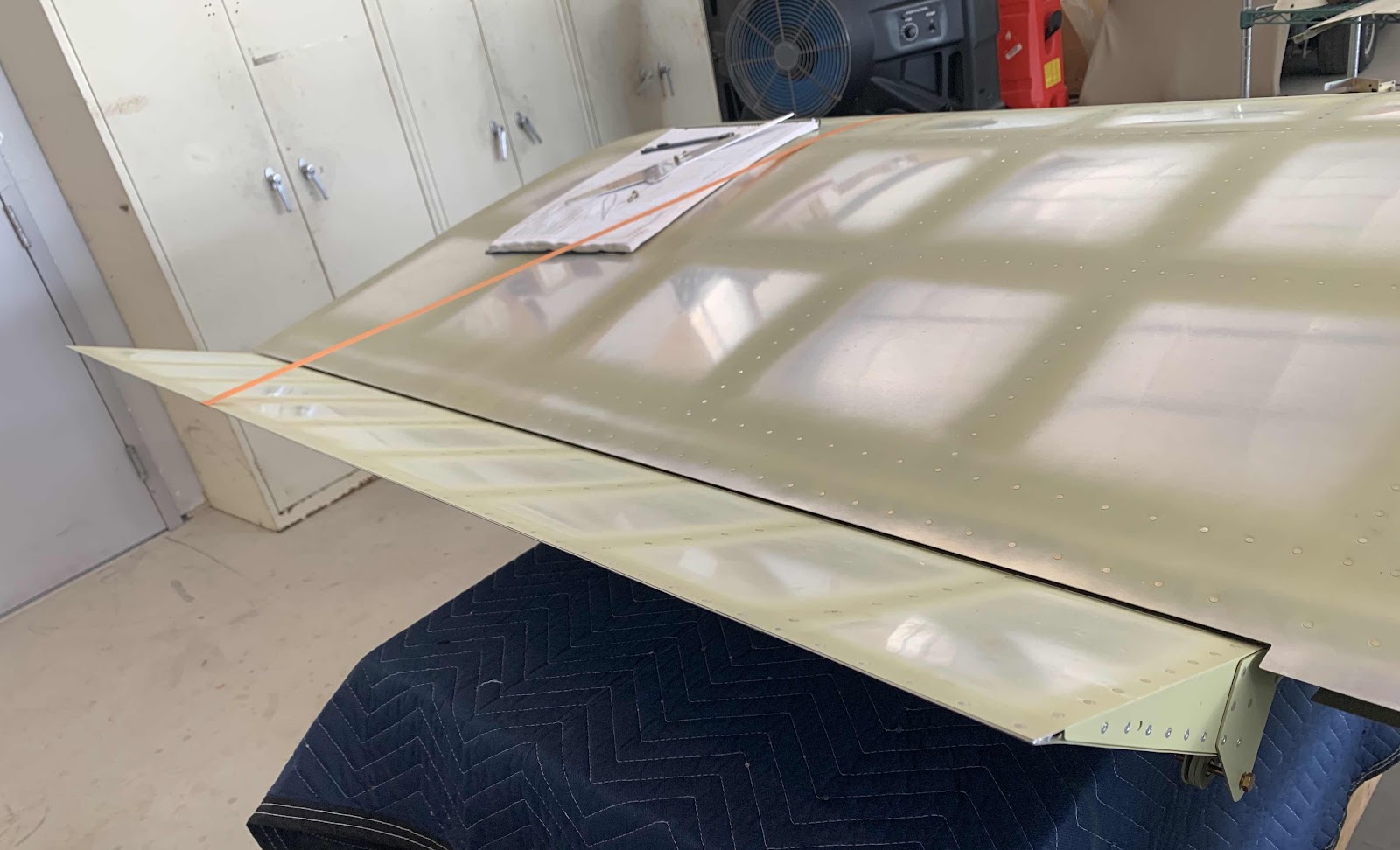
.....and outboard to inboard.

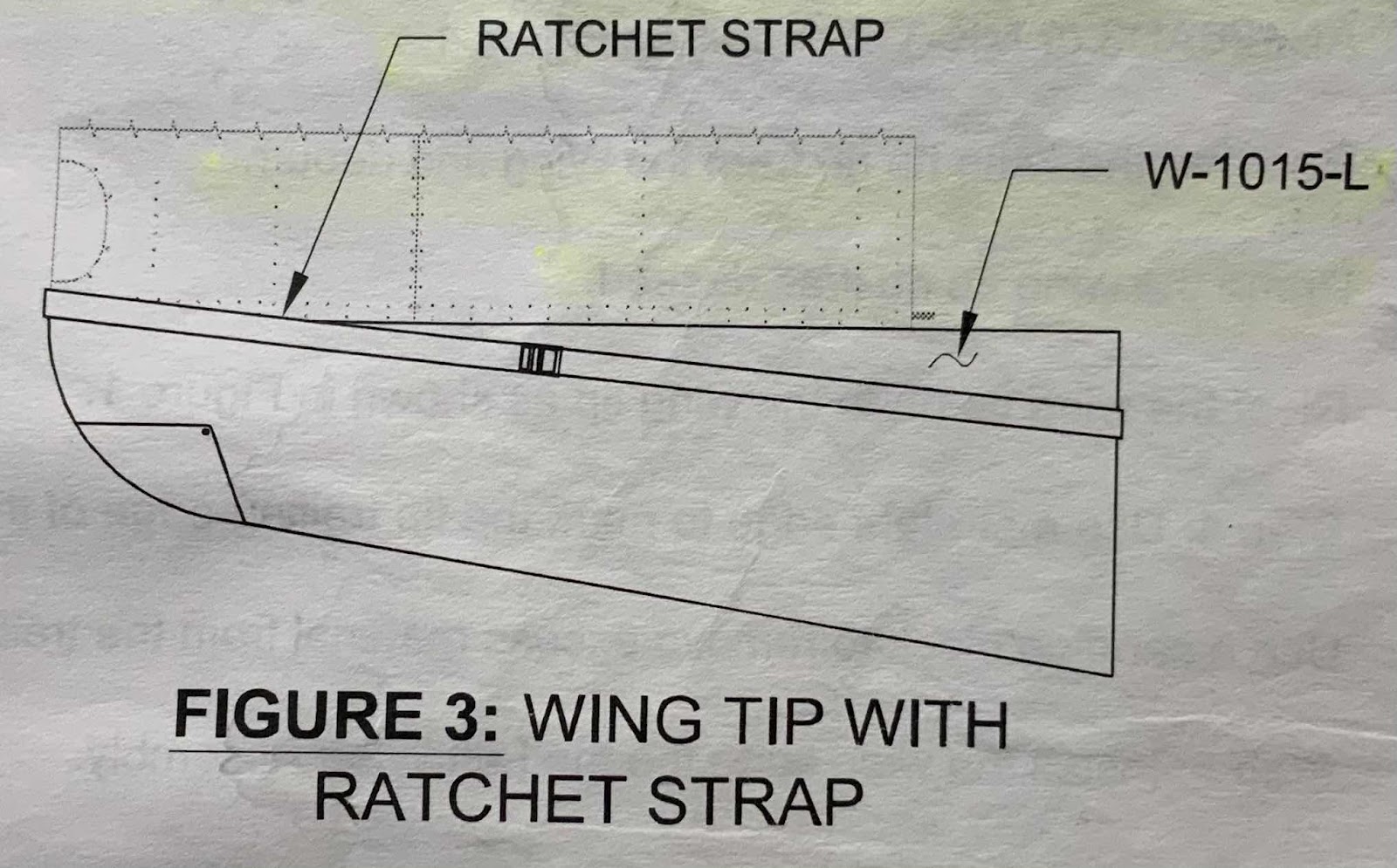
Next, the Wing Tip gets inserted into the Wing. In order to hold the Wing Tip into position, the plans say to use a ratchet strap as shown in the plans excerpt below. This is designed to make sure the Wing Tip if fully seated against the inside of the Wing’s leading edge. I found this to be very difficult (maybe I wasn’t doing it right). I found it much easier for one person to hold the assembly in position and a second person to match-drill the required holes. I assume the ratchet strap idea is in case you are working by yourself. Probably a good idea, I just couldn’t get it to work.
So, once it was held in position (by a second person in my case), all the #40 holes in the Leading Edge Skin, Top Outboard Wing Skin and Bottom Outboard Wing Skin were match-drilled with the Wing Tip. The next two pictures shows the completed process for the top and bottom of the Wing Tip.
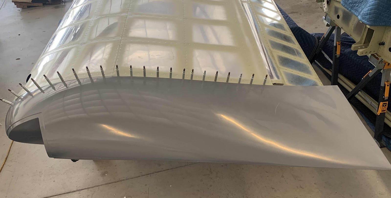
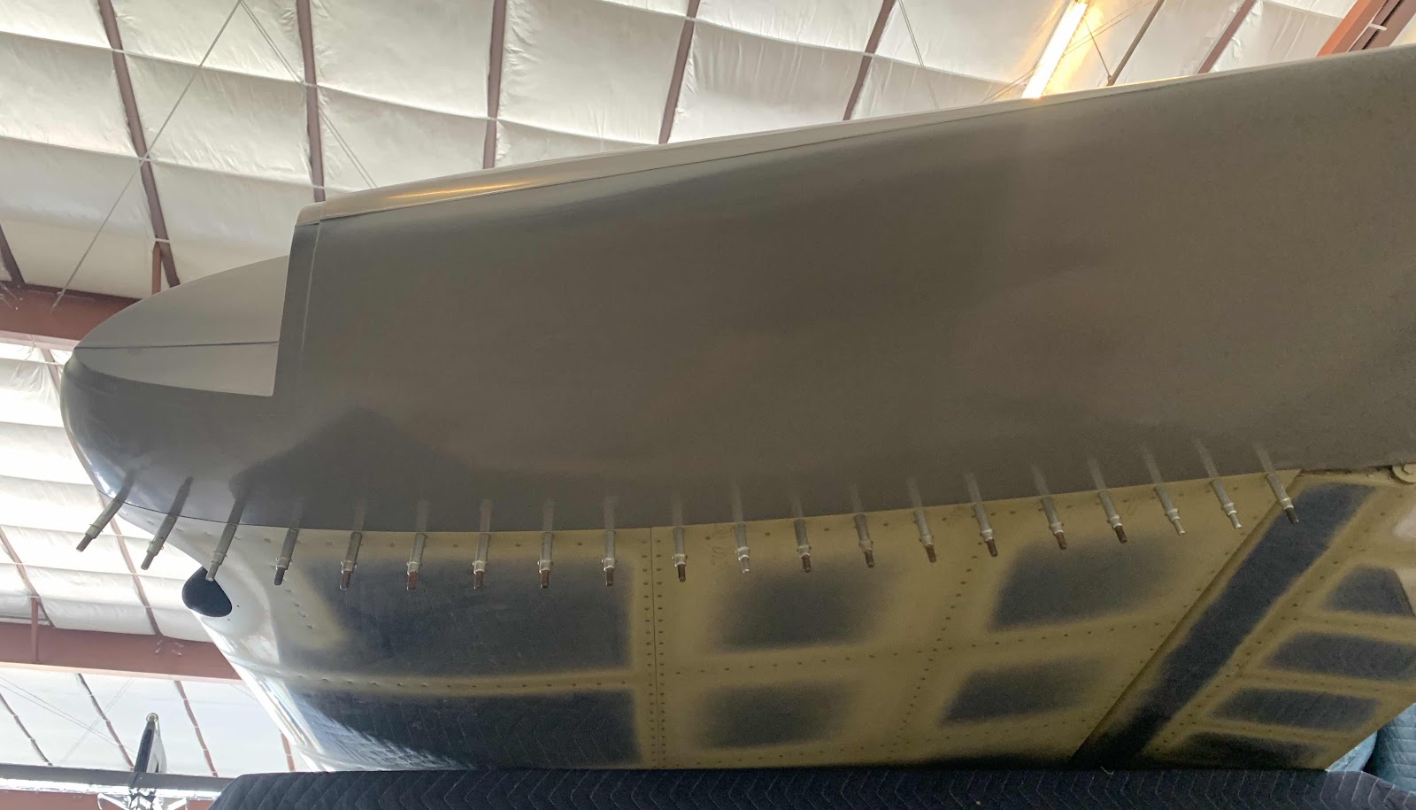
This is the initial fit for the “gap” between the Wing Tip and the Aileron. At little “wavy”, but can easily be fixed with some sanding. I won’t do any “sanding to fit” at this point, because I want to install the 42 nutplates onto the Wing Tip and screw it into its final position. Once that is done, I will make any necessary sanding adjustments to the Wing Tip.
