
Today’s session will initially focus on installing the Tail Light Adaptor Ring we purchased from Cleaveland Aircraft Tool. The tail light adaptor ring that comes with the kit would do the job just fine, but the aluminum is rather thin and I wanted something thicker/stronger. The Adaptor Ring from Cleaveland is much more robust at 1/8” thick and works directly with the AeroLED Suntail Anti-Collision/Position/Strobe Light. We didn’t use the installation instructions from the plans for this install because the Cleaveland Adaptor Right came with its own instructions.
To start, the aft side of the Rudder Bottom Fairing was sanded smooth to allow the Adaptor Ring to sit flush. To get the smooth, flat finish I wanted, I used a wood block and 220 grit sandpaper. Once it was flush, the Adaptor Ring was placed into position for proper alignment. For the install, I initially drilled #30 the top right hole, checked the alignment again and drilled the remaining five holes. Shown below are all six of the holes drilled #30 (four of the holes with clecos and the two holes between the clecos). NOTE: The two holes on the top and bottom of the Adaptor Ring will be used to attach the actual AeroLED Suntail to Ring.
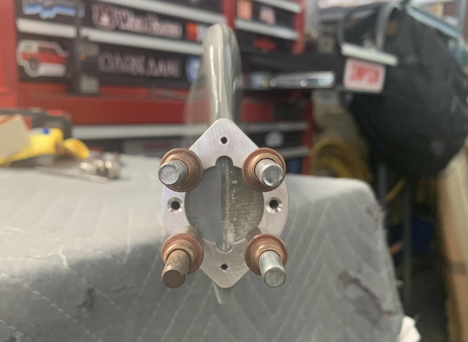
Here are a couple of pictures showing the Adaptor Ring alignment to the Rudder Bottom Fairing. At this point, I also marked the upper and lower light mounting holes on the Fairing.


Once all six of the Adaptor Ring mounting holes were drilled, the Ring was removed. Then, the upper and lower light mounting holes (marked prior to removing the Ring) were drilled to #30. These holes don’t actually do anything for the Suntail mount.....they just make room in the Fairing for the mounting screws to pass. Next, the center of the Fairing was found by drawing a line between each opposing hole.....as shown with the blue lines below. An certain amount of the Fairing will still need to be removed in the center to accept the AeroLED. However, I didn’t have the light at the shop today to see how much. I will do this during the next work session.

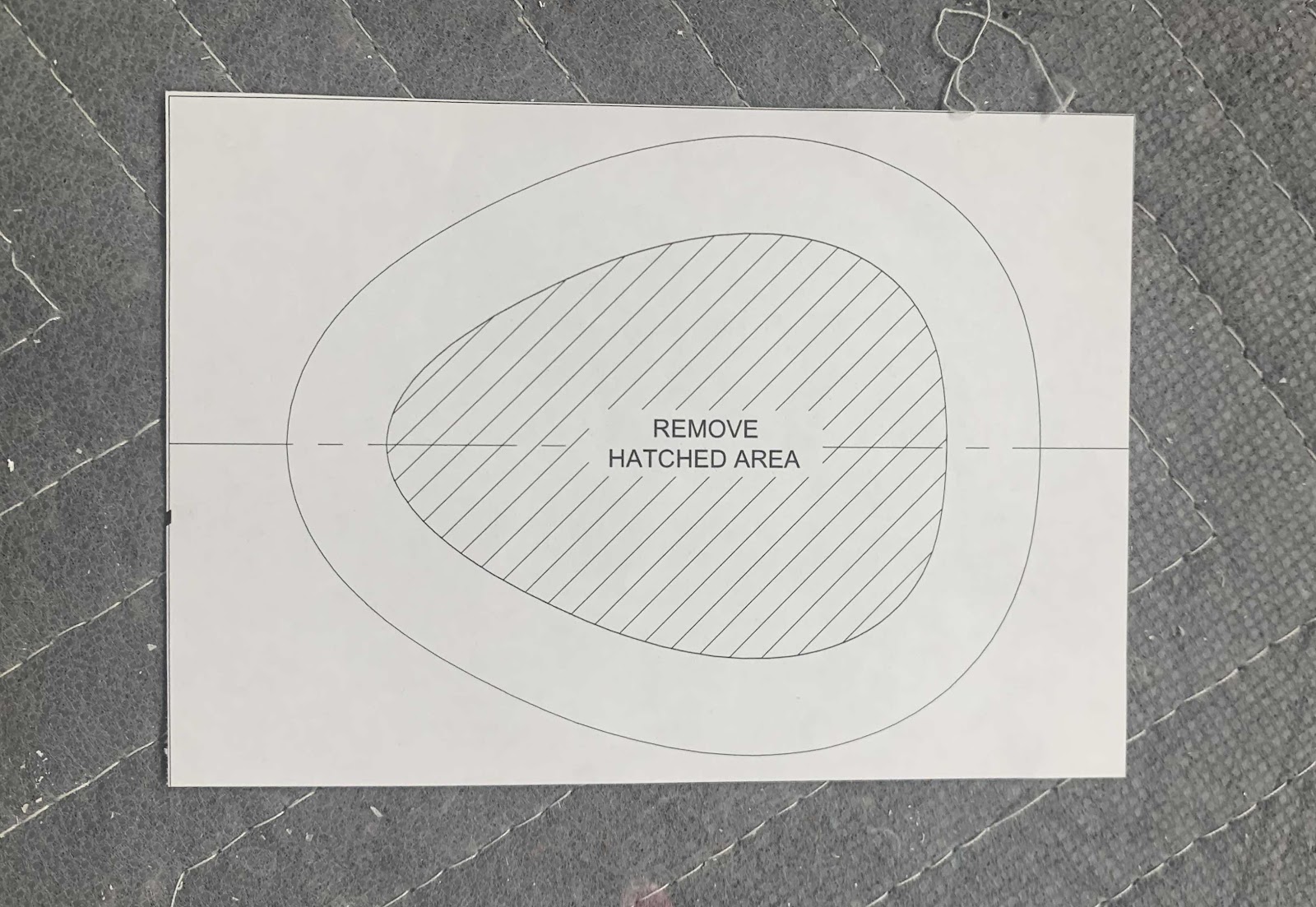
Moving on to the opposite end of the Fairing. There is a note in the plans that says, “It is necessary to modify the R-912 Bottom Rudder Fairing to clear the tail spring in the tail wheel configurations”. The next few steps are this modification. The picture below shows the template that was located in the plans. The template was cut out and glued to a stiffer material (packing paper) to make it a little stronger and easier to work with.
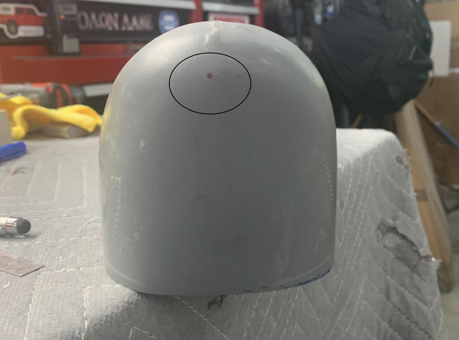
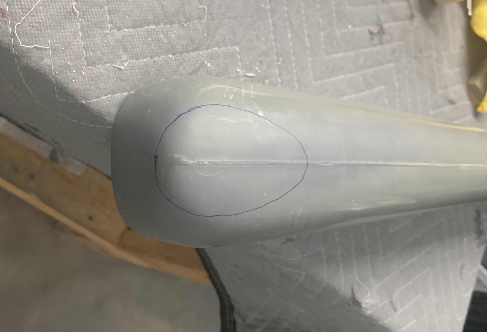
The next step was to measure and mark a location as directed by the plans. This location is shown with the blue dot in the circle below.
The template was then taped to the Fairing.....
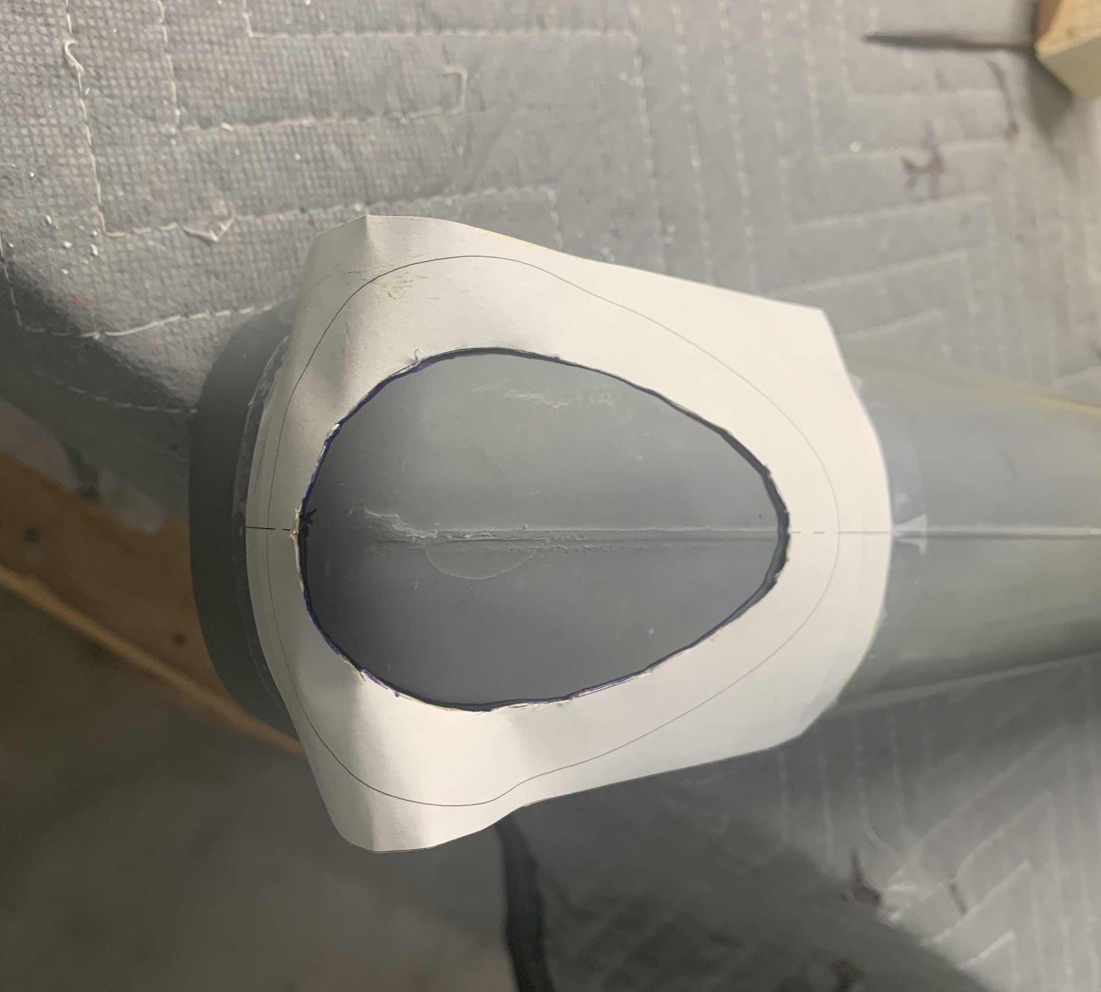
.....and traced onto the Fairing. Not the smoothest trace, but I got the idea of what needs to be done.
The material within the blue traced area will need to be removed. I initially removed most of the material with the cutoff wheel.....

.....and then sanded the Fairing with 220 grit sandpaper to the appropriate location. Still a few jagged edges, but a fiberglass patch will be used to cover the hole.
