
During the last session, I started the dimpling process on the Left Tank Skin. I used my pneumatic squeezer to dimple all the #8 screw hole locations and the #40 holes I could reach with the 3” yoke. To start today’s session, I dimpled the remaining #40 holes with the DRDT-2. In the picture below, you can see the Left Tank Skin and the DRDT-2 machine getting ready to work.

The picture below shows the completed Left Tank Skin with all the required dimples.

After completing the Left Tank Skin, I moved on to the Right. Initially, I had to clean the edges, make the lap joints on both training edges, and use the pneumatic squeezer to dimple all the #8 screw hole locations. Once that was completed, I used the DRDT-2 to dimple the remaining #40 holes. Shown below is the completed Right Tank Skin.

As I mentioned before, I will NOT be priming the inside of the Fuel Tanks; however, I will treat them with Alumiprep and Alodine. Both Tank Skins are now ready for that treatment.
The next step in the process is preparing the T-00007B Fuel Cap Flanges. In the picture below, the Fuel Cap Flanges are the red rings and the the Fuel Caps are grey. They were provided by Van’s in the packaging shown. This step required the 10 #40 holes in each Flange be machine countersunk to accept the dimples in the Fuel Tank Skins.

In order to keep the Flanges flat and stable for countersinking, I used three small pieces of 2x4 that I previously cut when making the Wing cradles.. The portion of the Flange that accepts the cap sticks down (into the Fuel Tank once installed) and doesn’t allow the cap to remain flat (rocks to the side). So, the use of the 2x4’s solved that problem.

After many test fits, the completed Flanges are shown below with their respective Fuel Caps. You can see the shiny countersinks in each of the Flanges.

This is a view with the one of the Fuel Cap Flange clecoed into place on the Right Fuel Tank Skin. This is the opening in the Fuel Tanks that will be used to fill the tanks with 100LL avgas (until an alternative fuel is approved by the FAA).

Next, the T-1005BC Shims had to be separated, trimmed, and deburred. Here is the raw product provided from Van’s.....

.....and here are the four Shims separated and with clean edges.

Once separated, they were clecoed into place on the T-00006-L Tank Attach Bracket. Circled in the picture below are the two T-1005B Shims.....
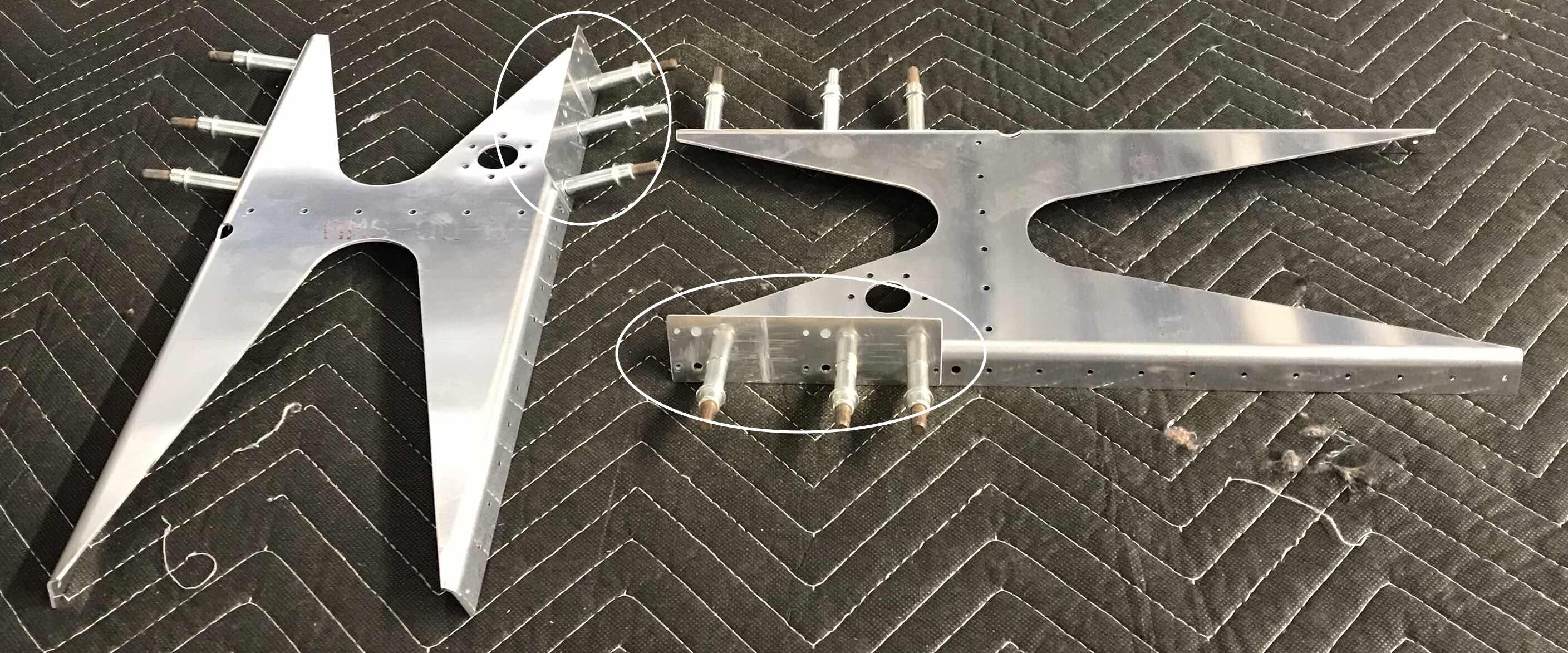
.....and circled below are the two T-1005C Shims clecoed to the Tank Attach Bracket.

I feel like lots of progress was made during this session. I will continue working from here tomorrow.