Continuing with the Fuel System.....
Today’s session started with the Andair Fuel Selector Valve (Part #FS20x2-T).
Here is the Fuel Selector right out of the box and it has three “settings”.....Left, Right, and Off. This Fuel Selector is VERY, VERY NICE! The tag tied to the mounting hole warns against operating the Selector “dry” with no fuel in the system and to use Loctite 648 on the screws that attach the elbow fittings to the housing.
The first step was to remove the red lever from the Selector. To do this, you lift up the knob up to expose the attaching screw. The small angled allen key was supplied in the kit.
Once the Lever is removed, the pieces look like this....valve body on the left, faceplate in the middle (after I countersunk the three attach holes for MS24693-C273 screws) and Lever on the right. The little screw that was removed in the step above, screws into the top of the cylinder the arrow is pointing at in the picture.
Next, the instructions have you install the elbow fittings to that valve body with the screws supplied from Andair. Now, if you look at the first picture posted above of the Fuel Selector, the elbow fittings are NOT in the same orientation as in the plans excerpt below. The elbow fittings pull straight out front the valve body and can be reinserted to the proper orientation (as shown below).
Once the elbow fittings were in the proper orientation, I began to install the supplied screws. As I mentioned above, Andair says to use Loctite 648 to install the screws. Here’s the appropriate stuff to use.....
I installed the first screw...
.....and then the other three on this elbow fitting. Then, installed the other two elbow fittings to the valve body. Additionally, in the picture above and below, you can see two of the three K1000-3 nutplates riveted to the valve body (circled).
Now, the valve body and the faceplate are attached to the F-14102 Fuel Selector Valve Bracket.....
.....and then the lever is reinstalled.
Here is another look at the Fuel Selector from the Firewall looking aft.
Moving on to the Andair Fuel Boost Pump (Part #ES-PX375-TC).
To begin, an ES-31890 ring terminal (crimped on the black wire) and ES-421-0108 female spade connector (crimped on the red wire) were installed as shown in the excerpt below. (The actual Fuel Boost Pump will be shown below).
Here is the Andair Fuel Filter (Part #Fuel-FX375-MK)
The Fuel Filter was removed from the box and pipe thread sealant (Permatex thread sealant #59214) was applied to the 1/4 NPT threads. It was then threaded into the 1/4 NPT end of the Fuel Boost Pump. Here are the two parts joined together. Additionally, you can see the ring terminal and spade connector crimped on the red and black wires as prepared above.
Once the two are joined together, the Fuel Boost Pump is attached to the F-14108A and F-14108B Fuel Pump Brackets with four AN515-8R8 screws.
The ring terminal end of the black wire is attached between the Fuel Pump Bracket and screw head (shown below).

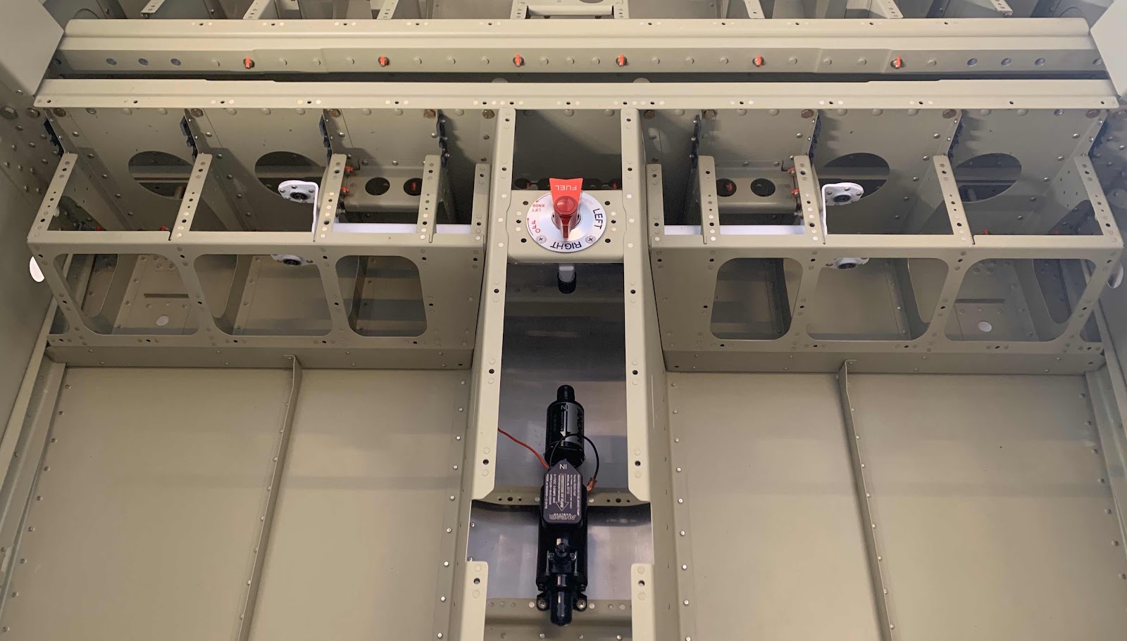
This picture shows the Fuel Selector Valve and Fuel Boost Pump installed on the plane.

Now, with Part 2 and today’s session completed, the plane is now ready to receive the cabin Fuel Lines.....when they arrive.
