
During the last session, I installed the two Flap Torque Arms and Flap Crank. Today, I will prepare and install the ES 85615-10 Linear Actuator (Flap Motor). The first step is to drill an angled “1/16” hole through the upper lip of the extension shaft and should exit outside the profile of the jam-nut, but within its outside diameter”. All of those words look like this in the plans.....
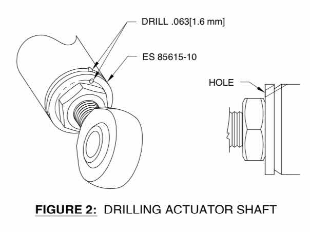
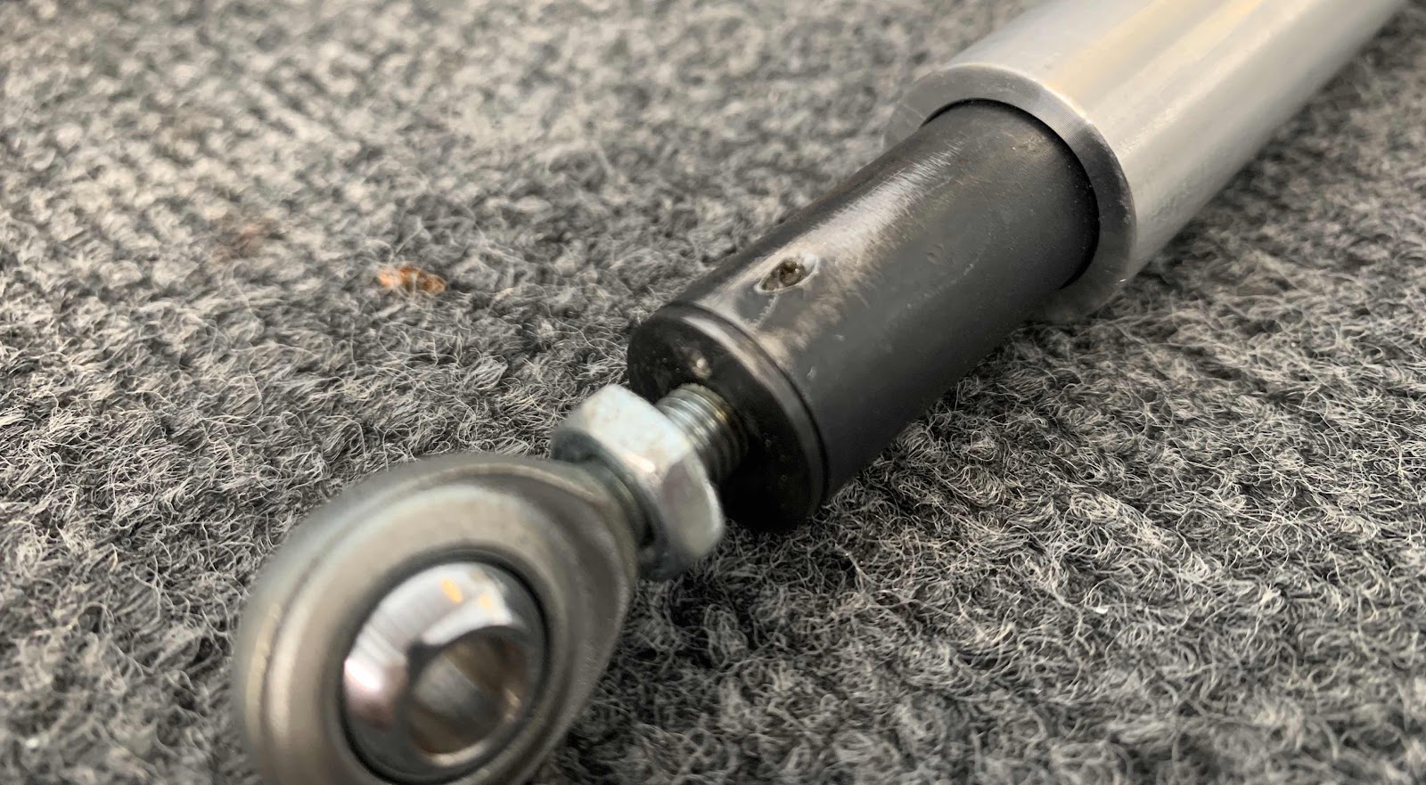
So, here is my 1/16” hole drilled through the extension shaft as described above. Now, the plans also contain the following NOTE:
“Avoid removal of the ES 85615-10 Linear Actuator jam-nut and rod end since the length of the assembly has been set at the factory”.
In the picture below, I kinda didn’t do that....well sorta! I initially tried to drill the hole with the jam-nut undisturbed. However, the drill bit would have drilled partially into the jam-nut (my angle was off ever so slightly). So, I unscrewed the jam-nut, finished drilling the hole and returned the jam-nut to it’s position from Van’s.
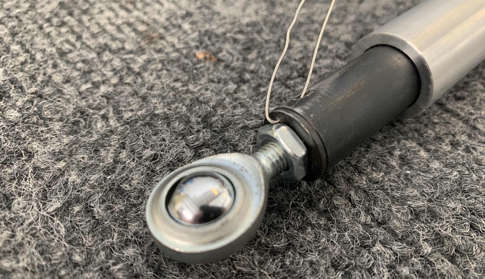
Then, inserted the .025 safety wire into the hole that was just drilled.
While working with the Flap Motor, I saw “Van’s” engraved on the back. Thought it was pretty cool.

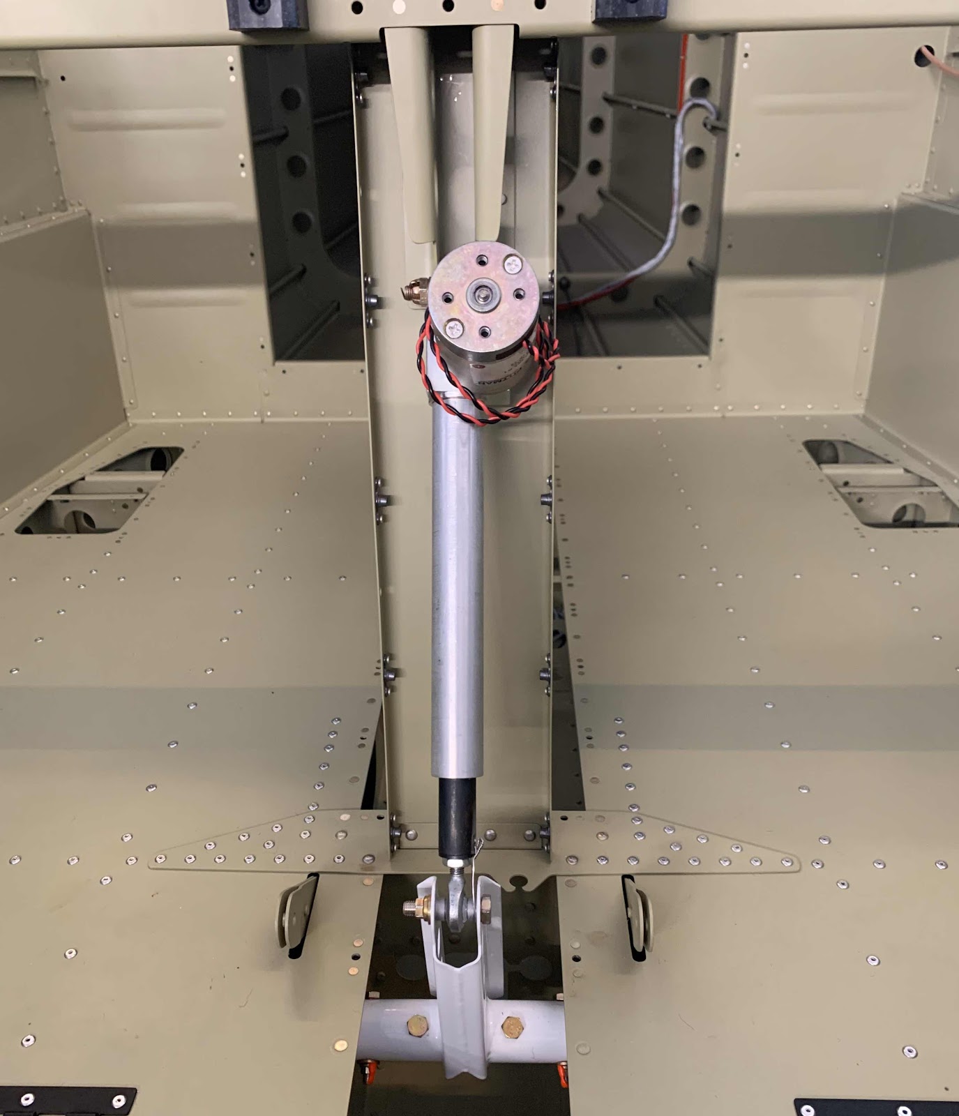
The top of the Flap Motor is secured to the F-01446-L & -R Motor Brackets with an AN4-12 bolt and hardware. Per the plans, wheel bearing grease was applied to the bolt.

The bottom of the Flap Motor (Extension Shaft) is secured to the WD-1023A Flap Crank with an AN3-12A and hardware. Additionally, safety wire is routed through the hole drilled in the extension shaft and around the .259X.375X.168 Bushing.

Here is the installed Flap Motor.....BOOM!


Section Complete
I ended up removing the Van's flap actuator and installing a different one. Please see
Modifications & Upgrades for the installation of the PH Aviation Services RV Max Flap Actuator.