
The work and pictures from this post are from January 3, 2024.
In the previous post, I mentioned the need for circuit protection for the wires coming from the shunt (as required by the electrical schematics from Aerotronics). To comply with that requirement, I decided to use these 1A Circuit Breakers from Aircraft Spruce. The two holes on the left side of the zees were actually the PERFECT size to accept the circuit breaker…..so, that’s where they went.
This view shows a couple of things:
- the two white wires attached to the shunt…..
- the two black ground wires attached to the standby alternator regulator (Post #7 and the case)

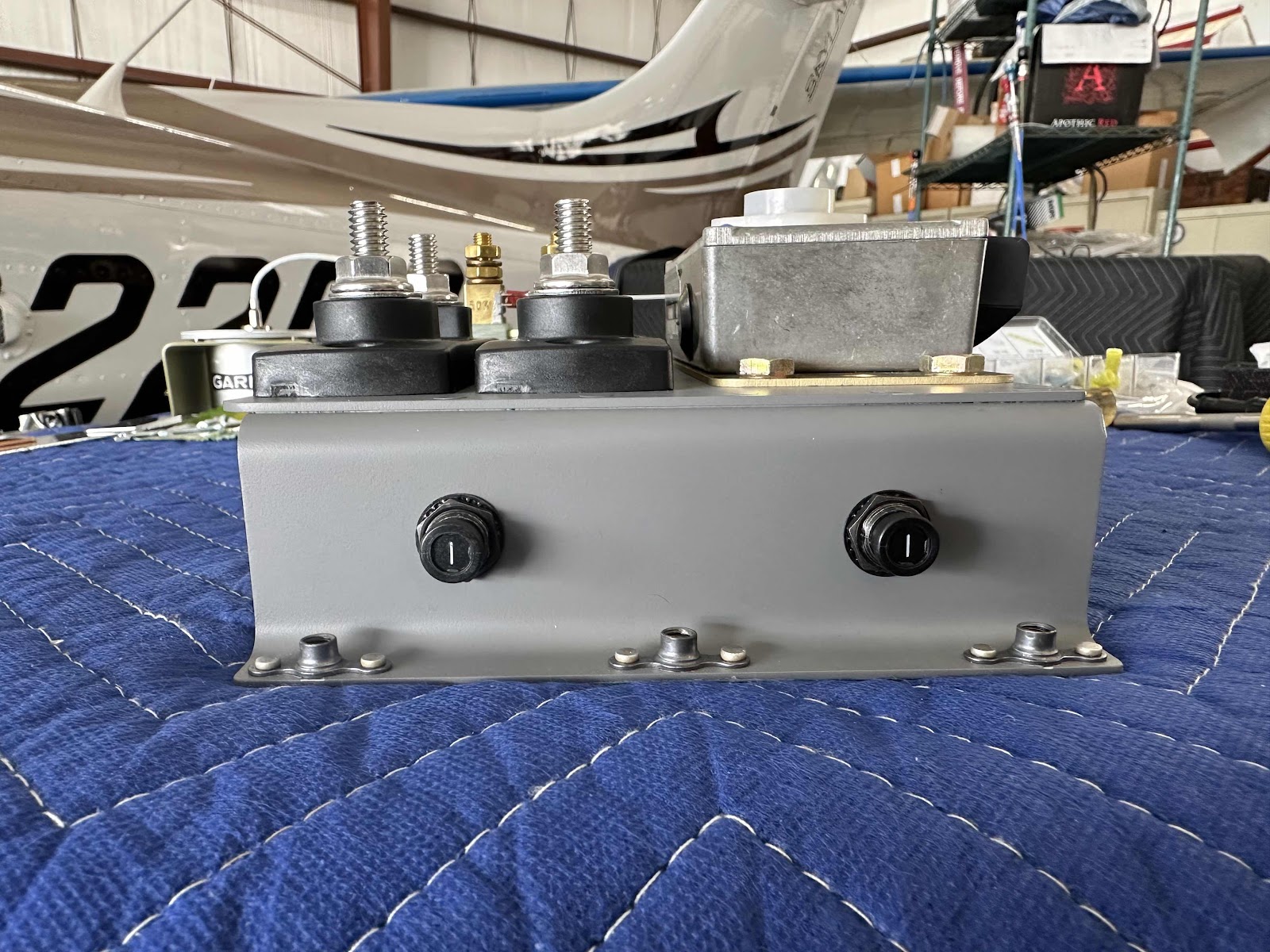
This is the opposite side of the bracket showing:
-the two white wires from the shunt attached to the 1A circuit breakers (through the rubber grommet)
-two black ground wires from the regulator attached to the ground post (I installed)

For the regulator ground(s) in the picture above, I ended up drilling a separate hole in the zee bracket to accomplish the grounding. By doing this, the bracket could be removed by only removing the five mounting bolts…..and the ground(s) and associated wiring on the bracket would not interfere or have to be disconnected. I thought it was the easiest way to do it instead of attaching it to one of the main bracket mounting bolts.
On the flanges of the zees that will make contact with the sub panel, you can see I sanded a couple of spots. I ultimately decided to sand the entire length of the flange(s) for grounding purposes. Additionally, I sanded the backside of the sub panel (forward side actually) that the bracket will contact when it was mounted. I used this Fine Sander Detail Kit from Aircraft Tool Supply Company to clean the mounting location on the sub panel.