
The work and pictures in this post are from August 25, 2023.
After deciding on the appropriate layout of the four parts, I started to actually fabricate the physical bracket. It took me several iterations to get exactly what I wanted…..which is why the bracket in the four pictures below seems somewhat “complete”. However, THIS version will also have to be MODIFIED….as you’ll see in a couple of future posts.
I initially used my 9” band saw to cut the “face plate” out of the .063 aluminum sheet and used 220 grit sand paper to smooth the edges and round the four corners. Next, I clamped each of the four parts to their respective spot on the face plate and match-drilled the appropriate sized mounting holes (the 10 holes in face plate).
Decision #3: How am I going to “raise” the face plate off the sub panel? To do this, I used the T-1012 Tank Attach Zee’s from Van’s. Those dude’s worked perfectly! They provided the appropriate stand off distance from the sub panel, contained holes in the flanges that were used to match-drill the face plate and acted as a “doubler” due to their thickness. After the 12 holes were match-drilled (six from each zee), I countersunk those holes to accept AN426AD-3 rivets.
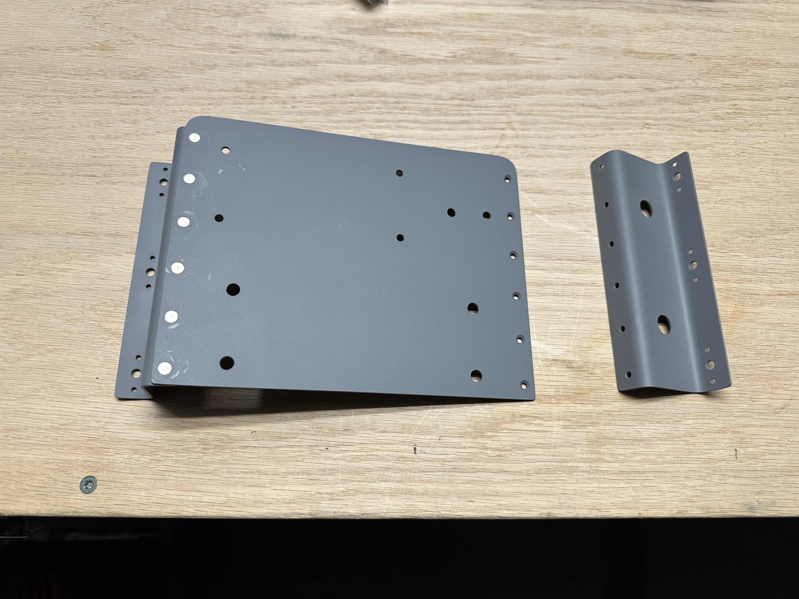
Then, I riveted the two tank attach zees to the face plate. Here you can see all 12 of the rivets installed and the 10 mounting holes for the four parts.

This view just shows the back side of the bracket with the shop side of the rivets.

After the three bracket pieces were riveted together, I installed the four parts on the face plate. I used AN3 bolts on the shunt (which fit perfectly in the notches on the base), AN4 bolts on the standby alternator regulator and AN525 screws on the current limiter bases (which also fit perfectly in the recessed mounting holes)…..and the appropriate sized washers and AN365 nuts on the back.
